2013 MERCEDES-BENZ CLA towing
[x] Cancel search: towingPage 205 of 352
(Y page 197) availability is limited or not avail-
able at all.
i The height of the ball coupling changes
with the load of the vehicle. If necessary,
use a trailer with a height-adjustable draw-
bar.
Driving tips
i Observe the notes on ESP ®
trailer stabi-
lisation ( Y page 70).
The maximum permissible speed for vehicle/
trailer combinations depends on the type of
trailer. Before beginning the journey, check
the trailer's documents to see what the max-
imum permitted speed is. Observe the legally
prescribed maximum speed in the relevant
country.
For certain Mercedes-Benz vehicles, the max-
imum permissible rear axle load is increased
when towing a trailer. Refer to the "Technical
data" section to find out whether this applies
to your vehicle. If you utilise any of the added
maximum rear axle load when towing a trailer,
the vehicle/trailer combination may not
exceed a maximum speed of 100 km/h for
reasons concerning the operating permit.
This also applies in countries in which the
permissible maximum speed for vehicle/
trailer combinations is above 100 km/h.
When towing a trailer, your vehicle's handling
characteristics will be different in comparison
to when driving without a trailer and it will
consume more fuel.
Change into a lower gear in good time on long
and steep downhill gradients. For vehicles
with automatic transmission, you need to
have selected manual drive program
M (Y page 156).
i This also applies if you have activated
cruise control, SPEEDTRONIC or DIS-
TRONIC PLUS.
This will use the braking effect of the engine,
so less braking will be required to maintain
vehicle speed. This relieves the load on the
brake system and prevents the brakes from
overheating and wearing too quickly. If you
need additional braking, depress the brake
pedal repeatedly rather than continuously.
i Briefly depressing the accelerator pedal
on downhill gradients while the manual
drive program M is temporarily activated
(vehicles with automatic transmission): the
automatic transmission may switch back to
the last active automatic drive program E
or S. The automatic transmission may shift
to a higher gear. This can reduce the
engine's braking effect.
Driving tips
If the trailer swings from side to side:
XDo not accelerate.XDo not countersteer.XBrake if necessary.
R Maintain a greater distance from the vehi-
cle in front than when driving without a
trailer.
R Avoid braking abruptly. If possible, brake
gently at first to allow the trailer to run on.
Then, increase the braking force rapidly.
R The values given for gradient-climbing
capabilities from a standstill refer to sea
level. When driving in mountainous areas,
note that the power output of the engine,
and consequently the vehicle's gradient-
climbing capability, decrease with increas-
ing altitude.
Folding out the ball coupling
GWARNING
If you release the ball coupling or it does not
engage correctly when folding in, it will swing
out. Within pivoting range of the ball coupling,
there is an increased risk of an accident and
injury.
Only release the ball coupling if the pivoting
range is unobstructed. Always make sure that
the ball coupling engages when folding in.
Towing a trailer203Driving and parkingZ
Page 206 of 352
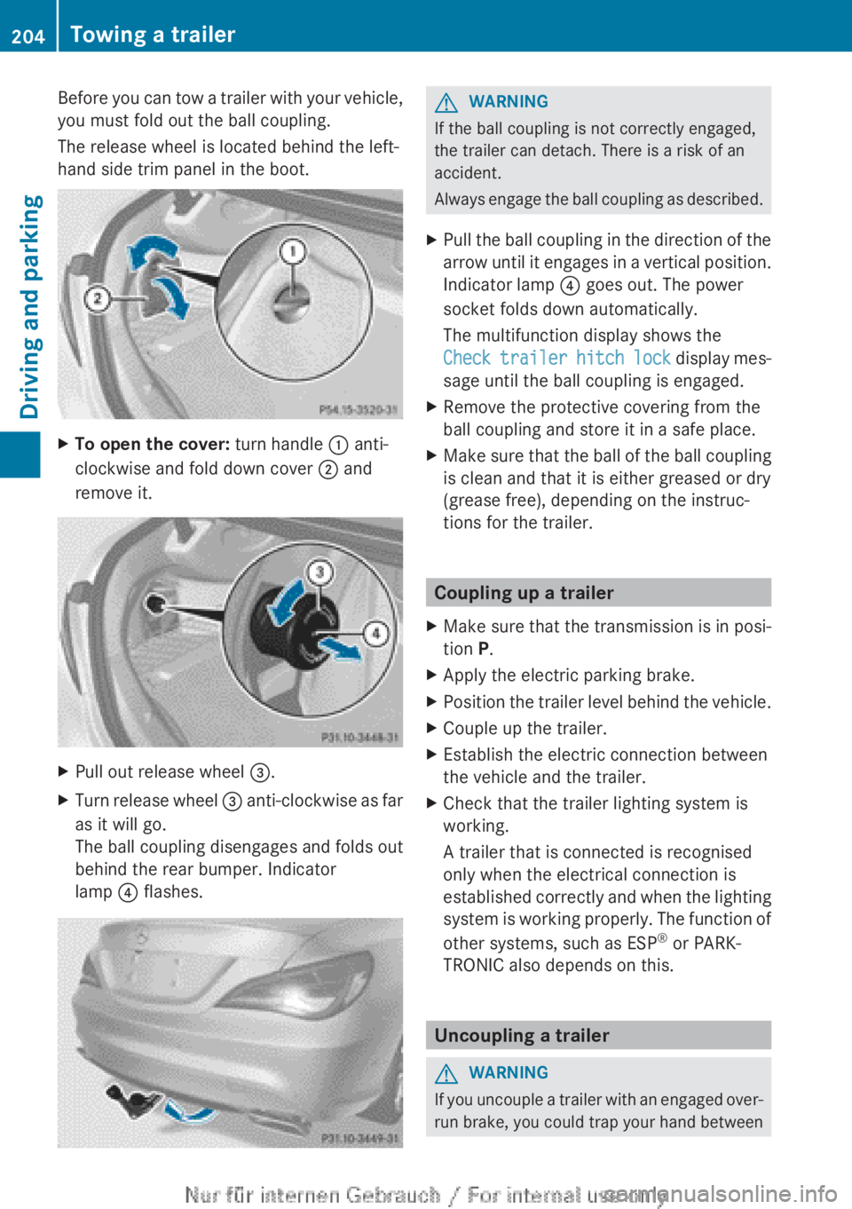
Before you can tow a trailer with your vehicle,
you must fold out the ball coupling.
The release wheel is located behind the left-
hand side trim panel in the boot.XTo open the cover: turn handle : anti-
clockwise and fold down cover ; and
remove it.XPull out release wheel =.XTurn release wheel = anti-clockwise as far
as it will go.
The ball coupling disengages and folds out
behind the rear bumper. Indicator
lamp ? flashes.GWARNING
If the ball coupling is not correctly engaged,
the trailer can detach. There is a risk of an
accident.
Always engage the ball coupling as described.
XPull the ball coupling in the direction of the
arrow until it engages in a vertical position.
Indicator lamp ? goes out. The power
socket folds down automatically.
The multifunction display shows the
Check trailer hitch lock display mes-
sage until the ball coupling is engaged.XRemove the protective covering from the
ball coupling and store it in a safe place.XMake sure that the ball of the ball coupling
is clean and that it is either greased or dry
(grease free), depending on the instruc-
tions for the trailer.
Coupling up a trailer
XMake sure that the transmission is in posi-
tion P.XApply the electric parking brake.XPosition the trailer level behind the vehicle.XCouple up the trailer.XEstablish the electric connection between
the vehicle and the trailer.XCheck that the trailer lighting system is
working.
A trailer that is connected is recognised
only when the electrical connection is
established correctly and when the lighting
system is working properly. The function of
other systems, such as ESP ®
or PARK-
TRONIC also depends on this.
Uncoupling a trailer
GWARNING
If you uncouple a trailer with an engaged over-
run brake, you could trap your hand between
204Towing a trailerDriving and parking
Page 207 of 352
the vehicle and the trailer drawbar. This poses
a risk of injury.
Do not uncouple a trailer with an engaged
overrun brake.
! Do not disconnect a trailer with an
engaged overrun brake. Otherwise, your
vehicle could be damaged by the rebound-
ing of the overrun brake.
! Remove the installed adapter cable
before folding in the ball coupling. Other-
wise, damage may occur to the rear
bumper and the adapter cable.XMake sure that the transmission is in posi-
tion P.XApply the electric parking brake.XSecure the trailer against rolling away.XRemove the trailer cable and decouple the
trailer.
Folding in the ball coupling
GWARNING
If you release the ball coupling or it does not
engage correctly when folding in, it will swing
out. Within pivoting range of the ball coupling,
there is an increased risk of an accident and
injury.
Only release the ball coupling if the pivoting
range is unobstructed. Always make sure that
the ball coupling engages when folding in.
XFold the ball coupling back in if you are not
using the trailer tow hitch.XPlace the protective covering on the ball
coupling.
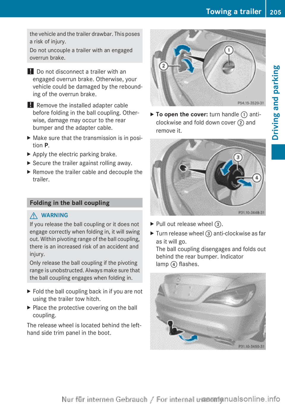
The release wheel is located behind the left-
hand side trim panel in the boot.
XTo open the cover: turn handle : anti-
clockwise and fold down cover ; and
remove it.XPull out release wheel =.XTurn release wheel = anti-clockwise as far
as it will go.
The ball coupling disengages and folds out
behind the rear bumper. Indicator
lamp ? flashes.Towing a trailer205Driving and parkingZ
Page 208 of 352
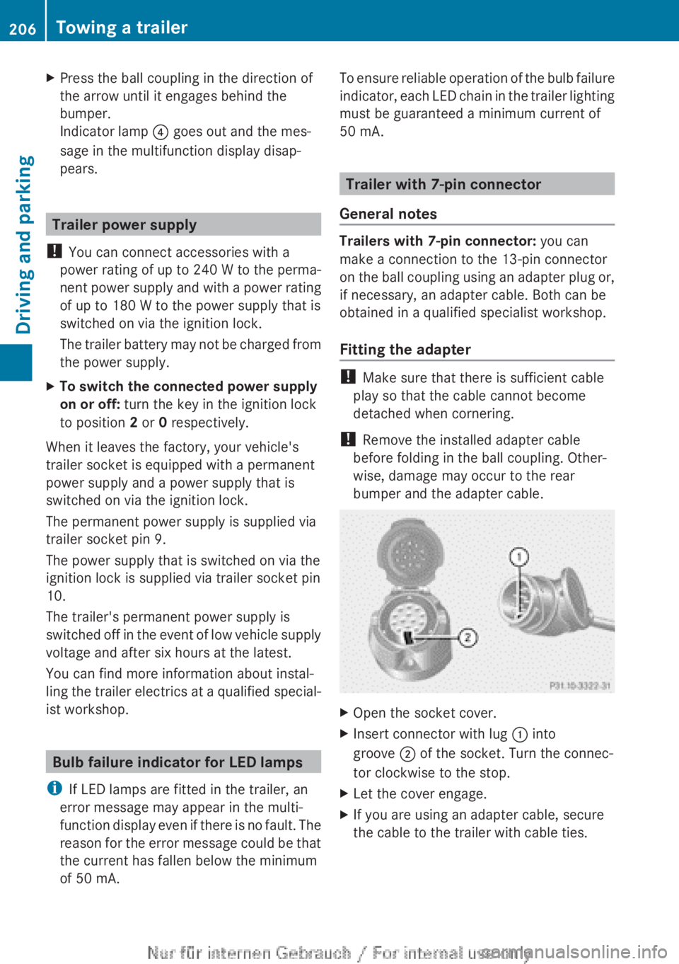
XPress the ball coupling in the direction of
the arrow until it engages behind the
bumper.
Indicator lamp ? goes out and the mes-
sage in the multifunction display disap-
pears.
Trailer power supply
! You can connect accessories with a
power rating of up to 240 W to the perma-
nent power supply and with a power rating
of up to 180 W to the power supply that is
switched on via the ignition lock.
The trailer battery may not be charged from
the power supply.
XTo switch the connected power supply
on or off: turn the key in the ignition lock
to position 2 or 0 respectively.
When it leaves the factory, your vehicle's
trailer socket is equipped with a permanent
power supply and a power supply that is
switched on via the ignition lock.
The permanent power supply is supplied via
trailer socket pin 9.
The power supply that is switched on via the
ignition lock is supplied via trailer socket pin
10.
The trailer's permanent power supply is
switched off in the event of low vehicle supply
voltage and after six hours at the latest.
You can find more information about instal-
ling the trailer electrics at a qualified special-
ist workshop.
Bulb failure indicator for LED lamps
i If LED lamps are fitted in the trailer, an
error message may appear in the multi-
function display even if there is no fault. The
reason for the error message could be that
the current has fallen below the minimum
of 50 mA.
To ensure reliable operation of the bulb failure
indicator, each LED chain in the trailer lighting
must be guaranteed a minimum current of
50 mA.
Trailer with 7-pin connector
General notes
Trailers with 7-pin connector: you can
make a connection to the 13-pin connector
on the ball coupling using an adapter plug or,
if necessary, an adapter cable. Both can be
obtained in a qualified specialist workshop.
Fitting the adapter
! Make sure that there is sufficient cable
play so that the cable cannot become
detached when cornering.
! Remove the installed adapter cable
before folding in the ball coupling. Other-
wise, damage may occur to the rear
bumper and the adapter cable.
XOpen the socket cover.XInsert connector with lug : into
groove ; of the socket. Turn the connec-
tor clockwise to the stop.XLet the cover engage.XIf you are using an adapter cable, secure
the cable to the trailer with cable ties.206Towing a trailerDriving and parking
Page 246 of 352
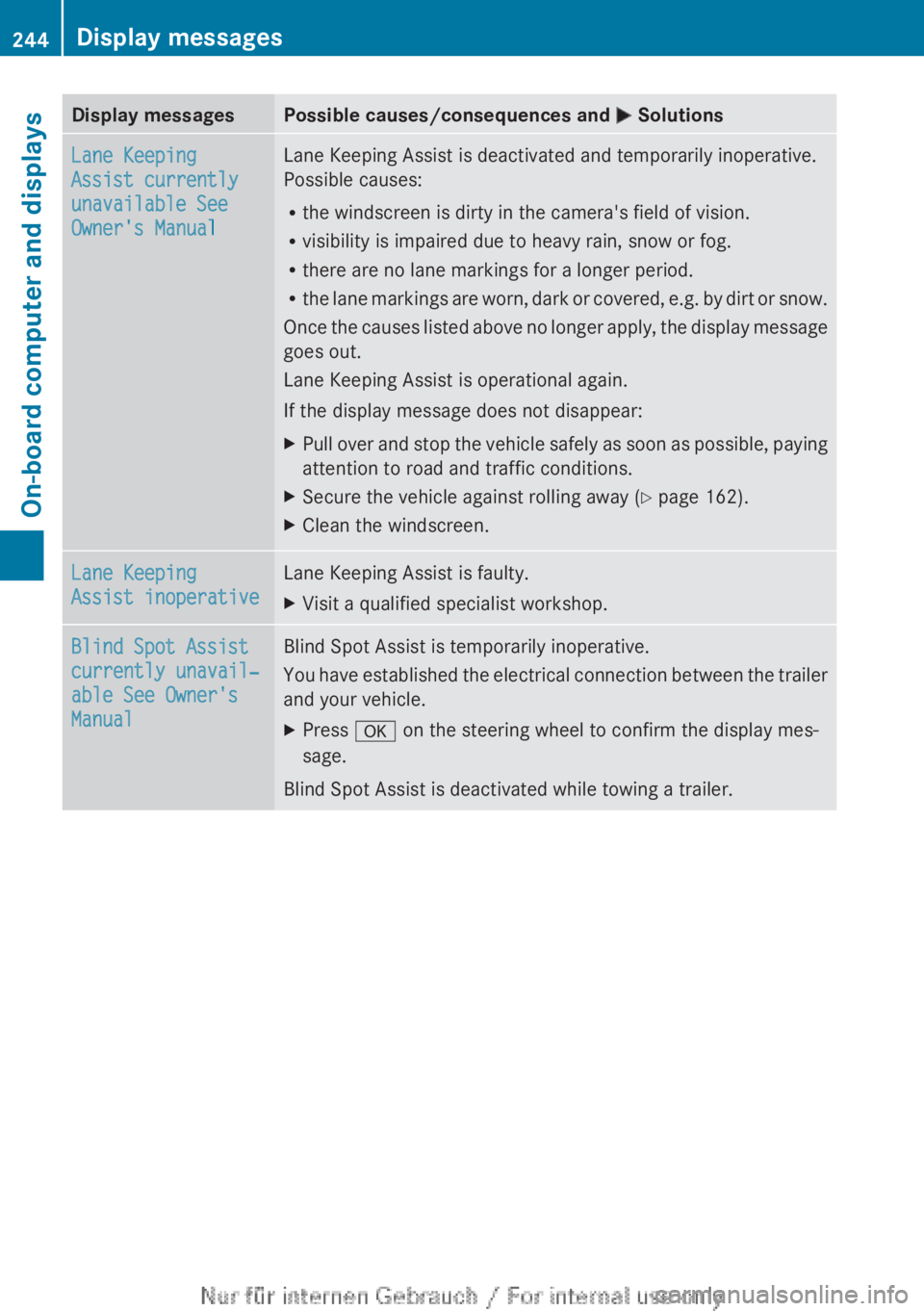
Display messagesPossible causes/consequences and M SolutionsLane Keeping
Assist currently
unavailable See
Owner's ManualLane Keeping Assist is deactivated and temporarily inoperative.
Possible causes:
R the windscreen is dirty in the camera's field of vision.
R visibility is impaired due to heavy rain, snow or fog.
R there are no lane markings for a longer period.
R the lane markings are worn, dark or covered, e.g. by dirt or snow.
Once the causes listed above no longer apply, the display message
goes out.
Lane Keeping Assist is operational again.
If the display message does not disappear:XPull over and stop the vehicle safely as soon as possible, paying
attention to road and traffic conditions.XSecure the vehicle against rolling away ( Y page 162).XClean the windscreen.Lane Keeping
Assist inoperativeLane Keeping Assist is faulty.XVisit a qualified specialist workshop.Blind Spot Assist
currently unavail‐
able See Owner's
ManualBlind Spot Assist is temporarily inoperative.
You have established the electrical connection between the trailer
and your vehicle.XPress a on the steering wheel to confirm the display mes-
sage.
Blind Spot Assist is deactivated while towing a trailer.
244Display messagesOn-board computer and displays
Page 269 of 352
Useful information ............................268
Loading guidelines ............................268
Stowage areas .................................. 268
Features ............................................. 274267Stowing and features
Page 270 of 352
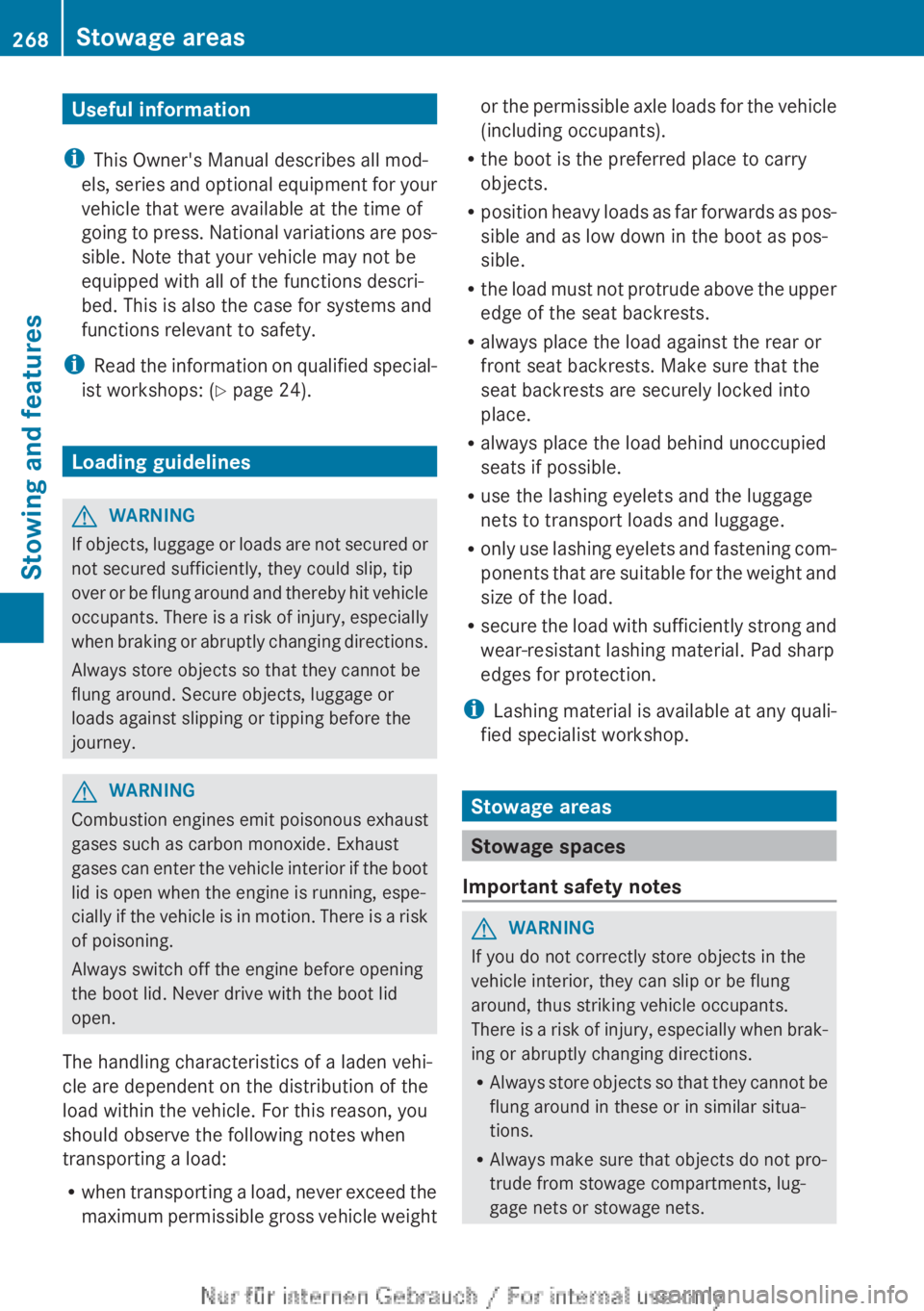
Useful information
i This Owner's Manual describes all mod-
els, series and optional equipment for your
vehicle that were available at the time of
going to press. National variations are pos-
sible. Note that your vehicle may not be
equipped with all of the functions descri-
bed. This is also the case for systems and
functions relevant to safety.
i Read the information on qualified special-
ist workshops: ( Y page 24).
Loading guidelines
GWARNING
If objects, luggage or loads are not secured or
not secured sufficiently, they could slip, tip
over or be flung around and thereby hit vehicle
occupants. There is a risk of injury, especially
when braking or abruptly changing directions.
Always store objects so that they cannot be
flung around. Secure objects, luggage or
loads against slipping or tipping before the
journey.
GWARNING
Combustion engines emit poisonous exhaust
gases such as carbon monoxide. Exhaust
gases can enter the vehicle interior if the boot
lid is open when the engine is running, espe-
cially if the vehicle is in motion. There is a risk
of poisoning.
Always switch off the engine before opening
the boot lid. Never drive with the boot lid
open.
The handling characteristics of a laden vehi-
cle are dependent on the distribution of the
load within the vehicle. For this reason, you
should observe the following notes when
transporting a load:
R when transporting a load, never exceed the
maximum permissible gross vehicle weight
or the permissible axle loads for the vehicle
(including occupants).
R the boot is the preferred place to carry
objects.
R position heavy loads as far forwards as pos-
sible and as low down in the boot as pos-
sible.
R the load must not protrude above the upper
edge of the seat backrests.
R always place the load against the rear or
front seat backrests. Make sure that the
seat backrests are securely locked into
place.
R always place the load behind unoccupied
seats if possible.
R use the lashing eyelets and the luggage
nets to transport loads and luggage.
R only use lashing eyelets and fastening com-
ponents that are suitable for the weight and
size of the load.
R secure the load with sufficiently strong and
wear-resistant lashing material. Pad sharp
edges for protection.
i Lashing material is available at any quali-
fied specialist workshop.
Stowage areas
Stowage spaces
Important safety notes
GWARNING
If you do not correctly store objects in the
vehicle interior, they can slip or be flung
around, thus striking vehicle occupants.
There is a risk of injury, especially when brak-
ing or abruptly changing directions.
R Always store objects so that they cannot be
flung around in these or in similar situa-
tions.
R Always make sure that objects do not pro-
trude from stowage compartments, lug-
gage nets or stowage nets.
268Stowage areasStowing and features
Page 271 of 352
RClose lockable stowage compartments
while driving.
R Stow and secure objects that are heavy,
hard, pointy, sharp-edged, fragile or too
large in the boot.
Observe the loading guidelines (Y page 268).
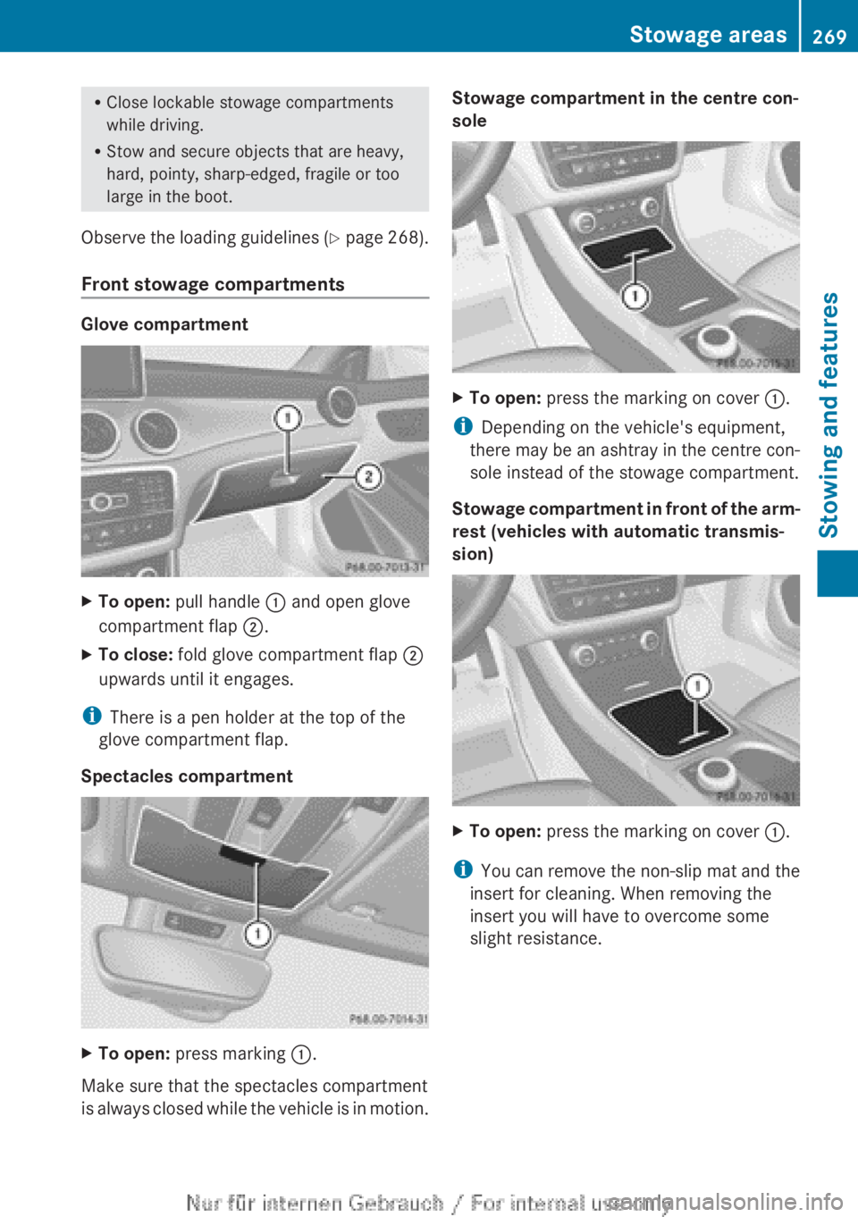
Front stowage compartments
Glove compartment
XTo open: pull handle : and open glove
compartment flap ;.XTo close: fold glove compartment flap ;
upwards until it engages.
i There is a pen holder at the top of the
glove compartment flap.
Spectacles compartment
XTo open: press marking :.
Make sure that the spectacles compartment
is always closed while the vehicle is in motion.
Stowage compartment in the centre con-
soleXTo open: press the marking on cover :.
i
Depending on the vehicle's equipment,
there may be an ashtray in the centre con-
sole instead of the stowage compartment.
Stowage compartment in front of the arm-
rest (vehicles with automatic transmis-
sion)
XTo open: press the marking on cover :.
i
You can remove the non-slip mat and the
insert for cleaning. When removing the
insert you will have to overcome some
slight resistance.
Stowage areas269Stowing and featuresZ