2013 MERCEDES-BENZ CLA clock
[x] Cancel search: clockPage 133 of 352
Setting the air distribution
THERMATIC automatic climate control
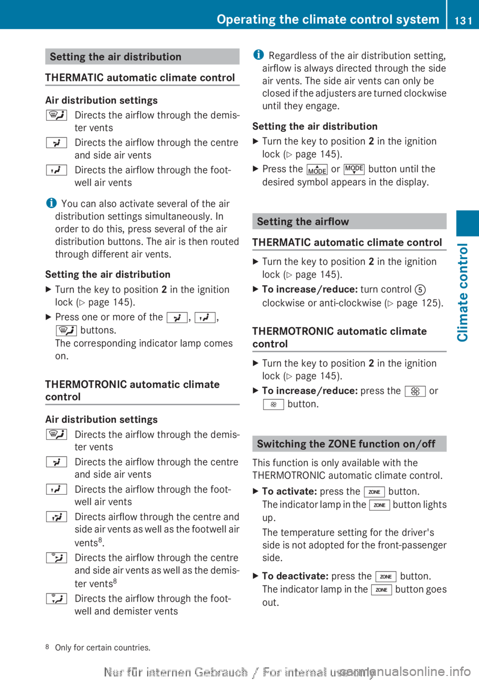
Air distribution settings
¯Directs the airflow through the demis-
ter ventsPDirects the airflow through the centre
and side air ventsODirects the airflow through the foot-
well air vents
i You can also activate several of the air
distribution settings simultaneously. In
order to do this, press several of the air
distribution buttons. The air is then routed
through different air vents.
Setting the air distribution
XTurn the key to position 2 in the ignition
lock ( Y page 145).XPress one or more of the P, O ,
¯ buttons.
The corresponding indicator lamp comes
on.
THERMOTRONIC automatic climate
control
Air distribution settings
¯Directs the airflow through the demis-
ter ventsPDirects the airflow through the centre
and side air ventsODirects the airflow through the foot-
well air ventsSDirects airflow through the centre and
side air vents as well as the footwell air
vents 8
.bDirects the airflow through the centre
and side air vents as well as the demis-
ter vents 8aDirects the airflow through the foot-
well and demister ventsi Regardless of the air distribution setting,
airflow is always directed through the side
air vents. The side air vents can only be
closed if the adjusters are turned clockwise
until they engage.
Setting the air distributionXTurn the key to position 2 in the ignition
lock ( Y page 145).XPress the É or Ë button until the
desired symbol appears in the display.
Setting the airflow
THERMATIC automatic climate control
XTurn the key to position 2 in the ignition
lock ( Y page 145).XTo increase/reduce: turn control A
clockwise or anti-clockwise ( Y page 125).
THERMOTRONIC automatic climate
control
XTurn the key to position 2 in the ignition
lock ( Y page 145).XTo increase/reduce: press the K or
I button.
Switching the ZONE function on/off
This function is only available with the
THERMOTRONIC automatic climate control.
XTo activate: press the á button.
The indicator lamp in the á button lights
up.
The temperature setting for the driver's
side is not adopted for the front-passenger
side.XTo deactivate: press the á button.
The indicator lamp in the á button goes
out.8 Only for certain countries.Operating the climate control system131Climate control
Page 134 of 352
The temperature setting for the driver's
side is adopted for the front-passenger
side.
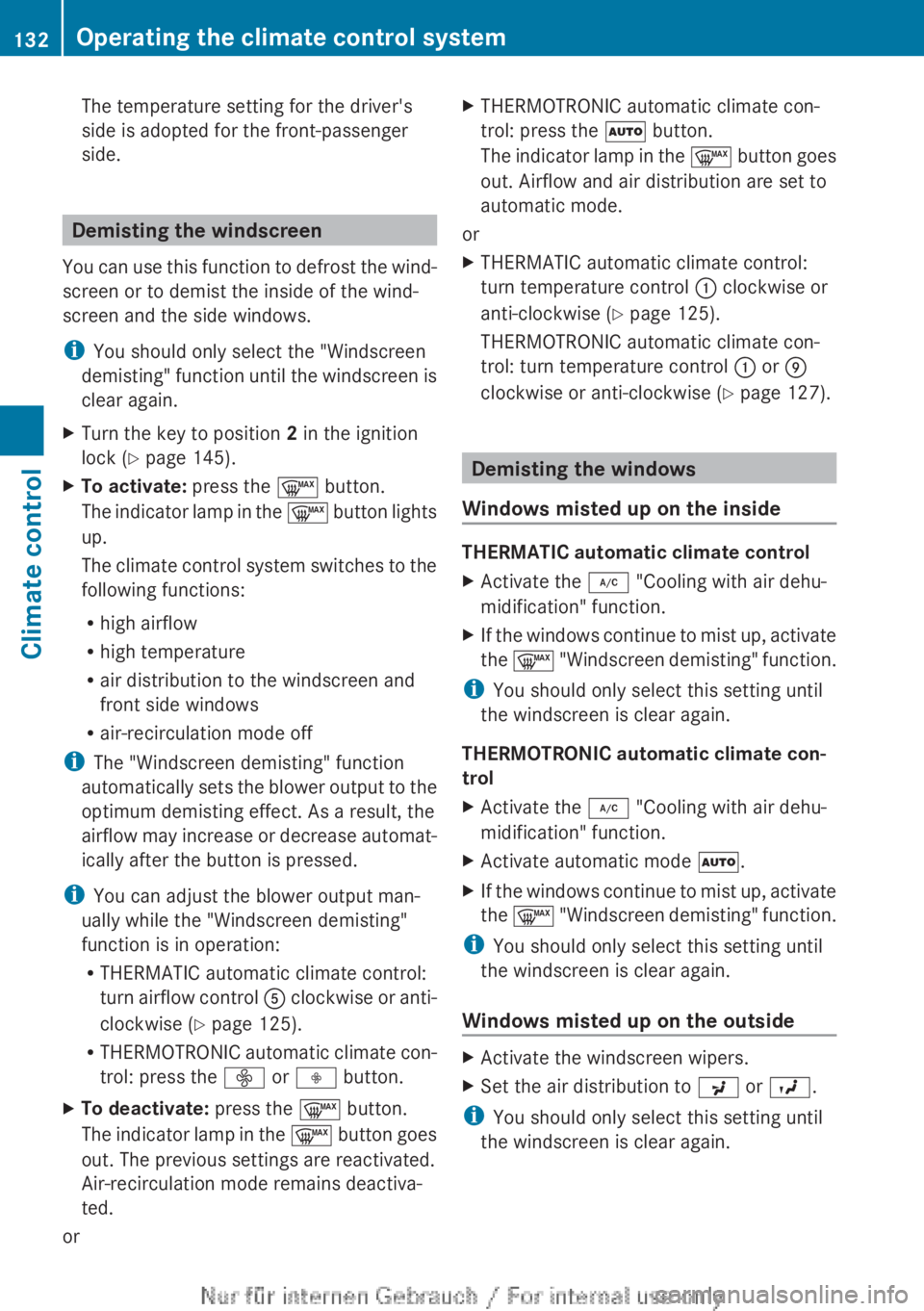
Demisting the windscreen
You can use this function to defrost the wind-
screen or to demist the inside of the wind-
screen and the side windows.
i You should only select the "Windscreen
demisting" function until the windscreen is
clear again.
XTurn the key to position 2 in the ignition
lock ( Y page 145).XTo activate: press the ¬ button.
The indicator lamp in the ¬ button lights
up.
The climate control system switches to the
following functions:
R high airflow
R high temperature
R air distribution to the windscreen and
front side windows
R air-recirculation mode off
i The "Windscreen demisting" function
automatically sets the blower output to the
optimum demisting effect. As a result, the
airflow may increase or decrease automat-
ically after the button is pressed.
i You can adjust the blower output man-
ually while the "Windscreen demisting"
function is in operation:
R THERMATIC automatic climate control:
turn airflow control A clockwise or anti-
clockwise ( Y page 125).
R THERMOTRONIC automatic climate con-
trol: press the ó or ô button.
XTo deactivate: press the ¬ button.
The indicator lamp in the ¬ button goes
out. The previous settings are reactivated.
Air-recirculation mode remains deactiva-
ted.
or
XTHERMOTRONIC automatic climate con-
trol: press the à button.
The indicator lamp in the ¬ button goes
out. Airflow and air distribution are set to
automatic mode.
or
XTHERMATIC automatic climate control:
turn temperature control : clockwise or
anti-clockwise ( Y page 125).
THERMOTRONIC automatic climate con-
trol: turn temperature control : or E
clockwise or anti-clockwise ( Y page 127).
Demisting the windows
Windows misted up on the inside
THERMATIC automatic climate control
XActivate the ¿ "Cooling with air dehu-
midification" function.XIf the windows continue to mist up, activate
the ¬ "Windscreen demisting" function.
i
You should only select this setting until
the windscreen is clear again.
THERMOTRONIC automatic climate con-
trol
XActivate the ¿ "Cooling with air dehu-
midification" function.XActivate automatic mode Ã.XIf the windows continue to mist up, activate
the ¬ "Windscreen demisting" function.
i
You should only select this setting until
the windscreen is clear again.
Windows misted up on the outside
XActivate the windscreen wipers.XSet the air distribution to P or O .
i
You should only select this setting until
the windscreen is clear again.
132Operating the climate control systemClimate control
Page 143 of 352
Display messagesPossible causes/consequences and M SolutionsThe auxiliary heating cannot be switched on or has switched itself
off.
There is too little fuel in the fuel tank.XRefuel at the nearest filling station.XMake another attempt to switch on the auxiliary heating using
the remote control.The auxiliary heating cannot be switched on or has switched itself
off.
The auxiliary heating is faulty.XHave the auxiliary heating checked at a qualified specialist
workshop.Adjusting the air vents
Important safety notes
GWARNING
Very hot or very cold air can flow from the air
vents. This could result in burns or frostbite in
the immediate vicinity of the air vents. There
is a risk of injury.
Make sure that all vehicle occupants always
maintain a sufficient distance to the air out-
lets. If necessary, redirect the airflow to
another area of the vehicle interior.
In order to ensure the direct flow of fresh air
through the air vents into the vehicle interior,
please observe the following notes:
R keep the air inlet between the windscreen
and the bonnet free of blockages, such as
ice, snow or leaves.
R never cover the vents or ventilation grilles
in the vehicle interior.
i Move the adjusters for the air vents ver-
tically or horizontally, to set the direction of
the airflow.
i Optimal climate control function is ach-
ieved by opening the air vents fully and set-
ting the adjusters to the middle position.
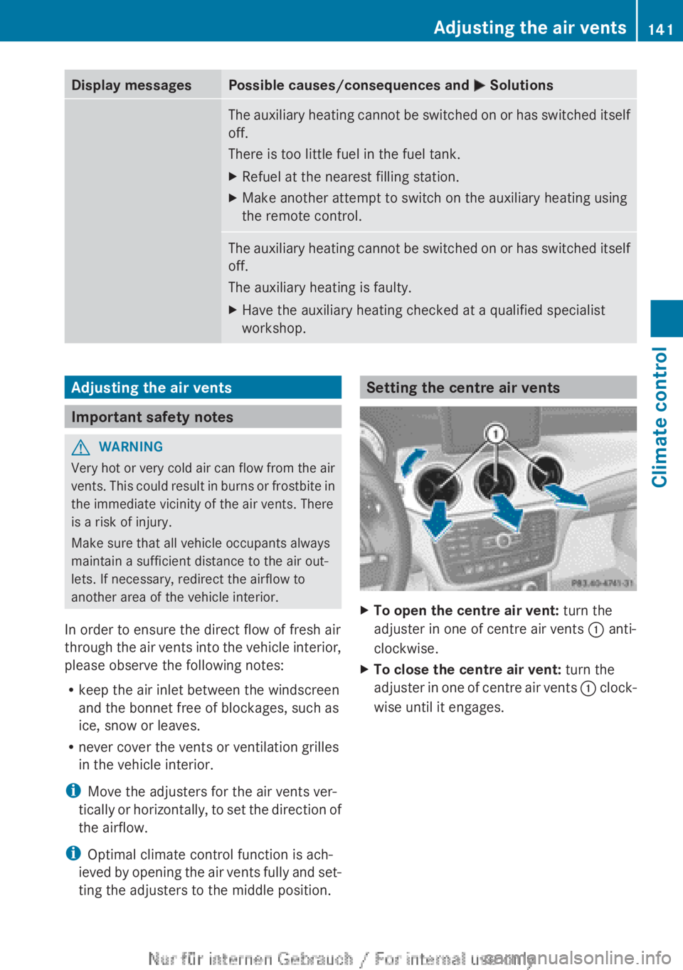
Setting the centre air ventsXTo open the centre air vent: turn the
adjuster in one of centre air vents : anti-
clockwise.XTo close the centre air vent: turn the
adjuster in one of centre air vents : clock-
wise until it engages.Adjusting the air vents141Climate controlZ
Page 144 of 352
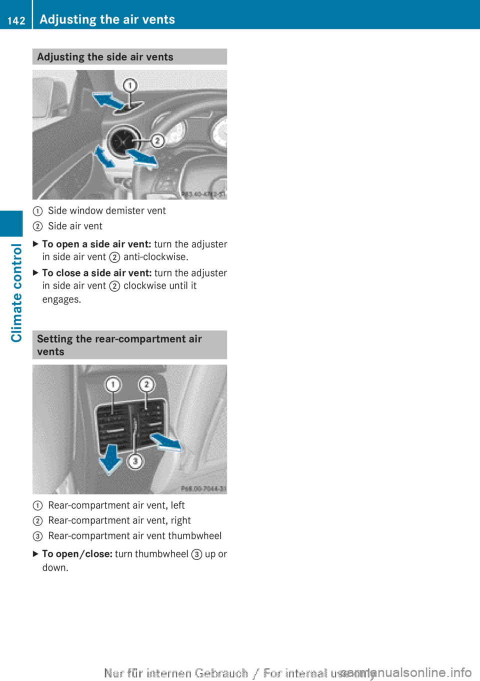
Adjusting the side air vents:Side window demister vent;Side air ventXTo open a side air vent: turn the adjuster
in side air vent ; anti-clockwise.XTo close a side air vent: turn the adjuster
in side air vent ; clockwise until it
engages.
Setting the rear-compartment air
vents
:Rear-compartment air vent, left;Rear-compartment air vent, right=Rear-compartment air vent thumbwheelXTo open/close: turn thumbwheel = up or
down.142Adjusting the air ventsClimate control
Page 162 of 352
on the ignition if you accidentally refuel
with the wrong fuel. Otherwise, the fuel will
enter the fuel system. Even small amounts
of the wrong fuel could result in damage to
the fuel system and the engine. The repair
costs are high. Notify a qualified specialist
workshop and have the fuel tank and fuel
lines drained completely.
! Overfilling the fuel tank could damage the
fuel system.
! Take care not to spill any fuel on painted
surfaces. You could otherwise damage the
paintwork.
! Use a filter when adding fuel from a fuel
can. The fuel lines and/or the diesel injec-
tion system could otherwise be blocked by
particles from the fuel can.
Do not get into the vehicle again during the
refuelling process. Otherwise, electrostatic
charge could build up again.
If you overfill the fuel tank, some fuel may
spray out when you remove the fuel pump
nozzle.
For further information on fuel and fuel quality
( Y page 337).
Refuelling
Opening/closing the fuel filler flap
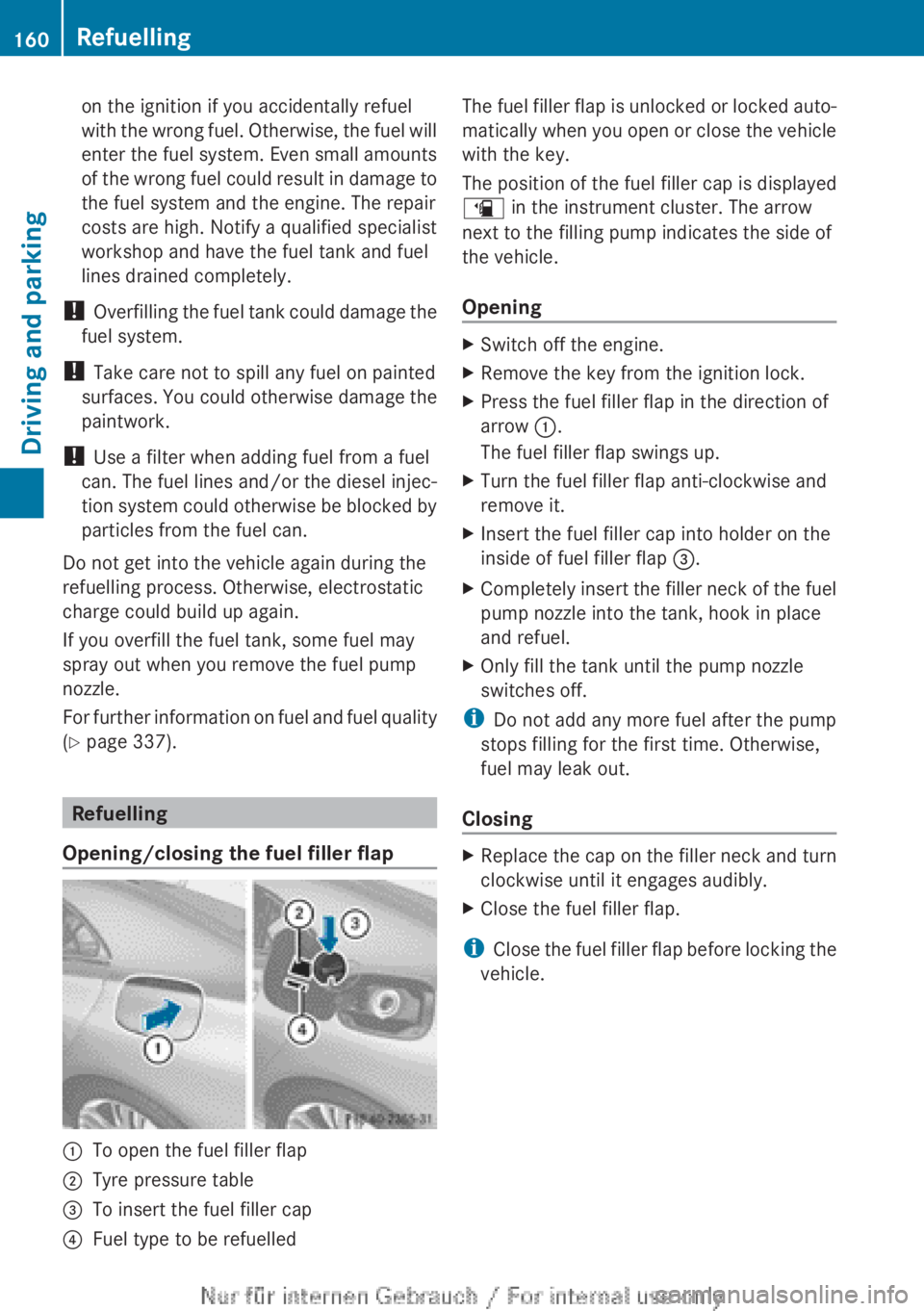
:To open the fuel filler flap;Tyre pressure table=To insert the fuel filler cap?Fuel type to be refuelledThe fuel filler flap is unlocked or locked auto-
matically when you open or close the vehicle
with the key.
The position of the fuel filler cap is displayed
æ in the instrument cluster. The arrow
next to the filling pump indicates the side of
the vehicle.
OpeningXSwitch off the engine.XRemove the key from the ignition lock.XPress the fuel filler flap in the direction of
arrow :.
The fuel filler flap swings up.XTurn the fuel filler flap anti-clockwise and
remove it.XInsert the fuel filler cap into holder on the
inside of fuel filler flap =.XCompletely insert the filler neck of the fuel
pump nozzle into the tank, hook in place
and refuel.XOnly fill the tank until the pump nozzle
switches off.
i Do not add any more fuel after the pump
stops filling for the first time. Otherwise,
fuel may leak out.
Closing
XReplace the cap on the filler neck and turn
clockwise until it engages audibly.XClose the fuel filler flap.
i Close the fuel filler flap before locking the
vehicle.
160RefuellingDriving and parking
Page 206 of 352
Before you can tow a trailer with your vehicle,
you must fold out the ball coupling.
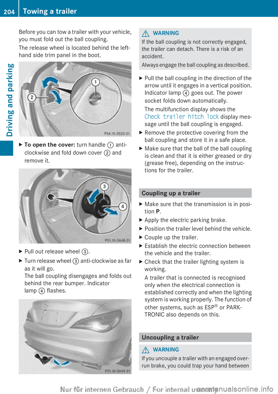
The release wheel is located behind the left-
hand side trim panel in the boot.XTo open the cover: turn handle : anti-
clockwise and fold down cover ; and
remove it.XPull out release wheel =.XTurn release wheel = anti-clockwise as far
as it will go.
The ball coupling disengages and folds out
behind the rear bumper. Indicator
lamp ? flashes.GWARNING
If the ball coupling is not correctly engaged,
the trailer can detach. There is a risk of an
accident.
Always engage the ball coupling as described.
XPull the ball coupling in the direction of the
arrow until it engages in a vertical position.
Indicator lamp ? goes out. The power
socket folds down automatically.
The multifunction display shows the
Check trailer hitch lock display mes-
sage until the ball coupling is engaged.XRemove the protective covering from the
ball coupling and store it in a safe place.XMake sure that the ball of the ball coupling
is clean and that it is either greased or dry
(grease free), depending on the instruc-
tions for the trailer.
Coupling up a trailer
XMake sure that the transmission is in posi-
tion P.XApply the electric parking brake.XPosition the trailer level behind the vehicle.XCouple up the trailer.XEstablish the electric connection between
the vehicle and the trailer.XCheck that the trailer lighting system is
working.
A trailer that is connected is recognised
only when the electrical connection is
established correctly and when the lighting
system is working properly. The function of
other systems, such as ESP ®
or PARK-
TRONIC also depends on this.
Uncoupling a trailer
GWARNING
If you uncouple a trailer with an engaged over-
run brake, you could trap your hand between
204Towing a trailerDriving and parking
Page 207 of 352
the vehicle and the trailer drawbar. This poses
a risk of injury.
Do not uncouple a trailer with an engaged
overrun brake.
! Do not disconnect a trailer with an
engaged overrun brake. Otherwise, your
vehicle could be damaged by the rebound-
ing of the overrun brake.
! Remove the installed adapter cable
before folding in the ball coupling. Other-
wise, damage may occur to the rear
bumper and the adapter cable.XMake sure that the transmission is in posi-
tion P.XApply the electric parking brake.XSecure the trailer against rolling away.XRemove the trailer cable and decouple the
trailer.
Folding in the ball coupling
GWARNING
If you release the ball coupling or it does not
engage correctly when folding in, it will swing
out. Within pivoting range of the ball coupling,
there is an increased risk of an accident and
injury.
Only release the ball coupling if the pivoting
range is unobstructed. Always make sure that
the ball coupling engages when folding in.
XFold the ball coupling back in if you are not
using the trailer tow hitch.XPlace the protective covering on the ball
coupling.
The release wheel is located behind the left-
hand side trim panel in the boot.
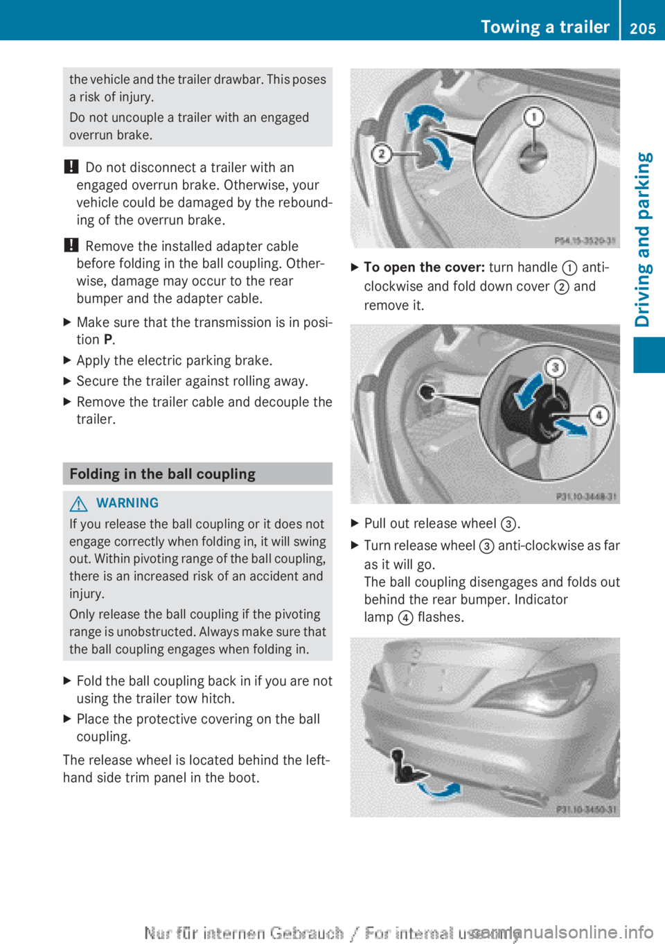
XTo open the cover: turn handle : anti-
clockwise and fold down cover ; and
remove it.XPull out release wheel =.XTurn release wheel = anti-clockwise as far
as it will go.
The ball coupling disengages and folds out
behind the rear bumper. Indicator
lamp ? flashes.Towing a trailer205Driving and parkingZ
Page 208 of 352
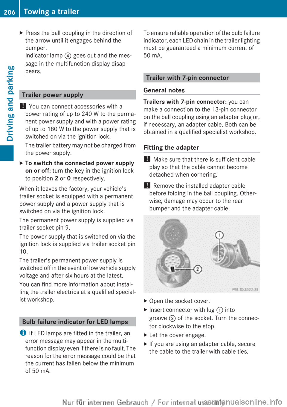
XPress the ball coupling in the direction of
the arrow until it engages behind the
bumper.
Indicator lamp ? goes out and the mes-
sage in the multifunction display disap-
pears.
Trailer power supply
! You can connect accessories with a
power rating of up to 240 W to the perma-
nent power supply and with a power rating
of up to 180 W to the power supply that is
switched on via the ignition lock.
The trailer battery may not be charged from
the power supply.
XTo switch the connected power supply
on or off: turn the key in the ignition lock
to position 2 or 0 respectively.
When it leaves the factory, your vehicle's
trailer socket is equipped with a permanent
power supply and a power supply that is
switched on via the ignition lock.
The permanent power supply is supplied via
trailer socket pin 9.
The power supply that is switched on via the
ignition lock is supplied via trailer socket pin
10.
The trailer's permanent power supply is
switched off in the event of low vehicle supply
voltage and after six hours at the latest.
You can find more information about instal-
ling the trailer electrics at a qualified special-
ist workshop.
Bulb failure indicator for LED lamps
i If LED lamps are fitted in the trailer, an
error message may appear in the multi-
function display even if there is no fault. The
reason for the error message could be that
the current has fallen below the minimum
of 50 mA.
To ensure reliable operation of the bulb failure
indicator, each LED chain in the trailer lighting
must be guaranteed a minimum current of
50 mA.
Trailer with 7-pin connector
General notes
Trailers with 7-pin connector: you can
make a connection to the 13-pin connector
on the ball coupling using an adapter plug or,
if necessary, an adapter cable. Both can be
obtained in a qualified specialist workshop.
Fitting the adapter
! Make sure that there is sufficient cable
play so that the cable cannot become
detached when cornering.
! Remove the installed adapter cable
before folding in the ball coupling. Other-
wise, damage may occur to the rear
bumper and the adapter cable.
XOpen the socket cover.XInsert connector with lug : into
groove ; of the socket. Turn the connec-
tor clockwise to the stop.XLet the cover engage.XIf you are using an adapter cable, secure
the cable to the trailer with cable ties.206Towing a trailerDriving and parking