2013 MERCEDES-BENZ CLA lock
[x] Cancel search: lockPage 311 of 352
! If DISTRONIC PLUS or the HOLD function
is activated, the vehicle brakes automati-
cally in certain situations. To prevent dam-
age to the vehicle, deactivate DISTRONIC
PLUS and the HOLD function in the follow-
ing or other similar situations:
R when towing the vehicle
R in the car wash
! Only secure the tow cable or tow bar to
the towing eyes or, if available, to the trailer
tow hitch. You could otherwise damage the
vehicle.
! Observe the following points when towing
with a tow rope:
R Secure the tow rope on the same side on
both vehicles.
R Make sure that the tow rope is not longer
than legally permitted. Mark the tow rope
in the middle, e.g. with a white cloth
(30 x 30 cm). This will make other road
users aware that a vehicle is being
towed.
R Only secure the tow cable to the towing
eyes or, if available, to the trailer tow
hitch.
R Observe the brake lamps of the towing
vehicle while driving. Always maintain a
distance a distance so that the tow rope
does not sag.
R Do not use steel cables or chains to tow
your vehicle. You could otherwise dam-
age the vehicle.
! Do not use the towing eyes for recovery
purposes as this could damage the vehicle.
If in doubt, recover the vehicle with a crane.
! Pull away smoothly when towing away or
tow-starting a vehicle. If the tractive power
is too high, the vehicles could be damaged.
! You may tow the vehicle for a maximum
of 50 km. A towing speed of 50 km/h must
not be exceeded.For towing distances over 50 km, the front
axle or the entire vehicle must be raised
and transported.
! Vehicles with automatic transmission
must not be tow-started. The transmission
may otherwise be damaged.
Observe the legal requirements for the rele-
vant countries when towing and tow-starting.
It is better to have the vehicle transported
than to have it towed.
Vehicles with automatic transmission:
when towing a vehicle, the transmission must
be in position N.
The battery must be connected and charged.
Otherwise, you:
R cannot turn the key in the ignition lock to
position 2
R vehicles with automatic transmission:
cannot shift the transmission to position N
i Deactivate the automatic locking feature
( Y page 223). You could otherwise be
locked out when pushing or towing the
vehicle.
Deactivate tow-away protection
( Y page 71) before the vehicle is towed.Towing and tow-starting309Breakdown assistanceZ
Page 312 of 352
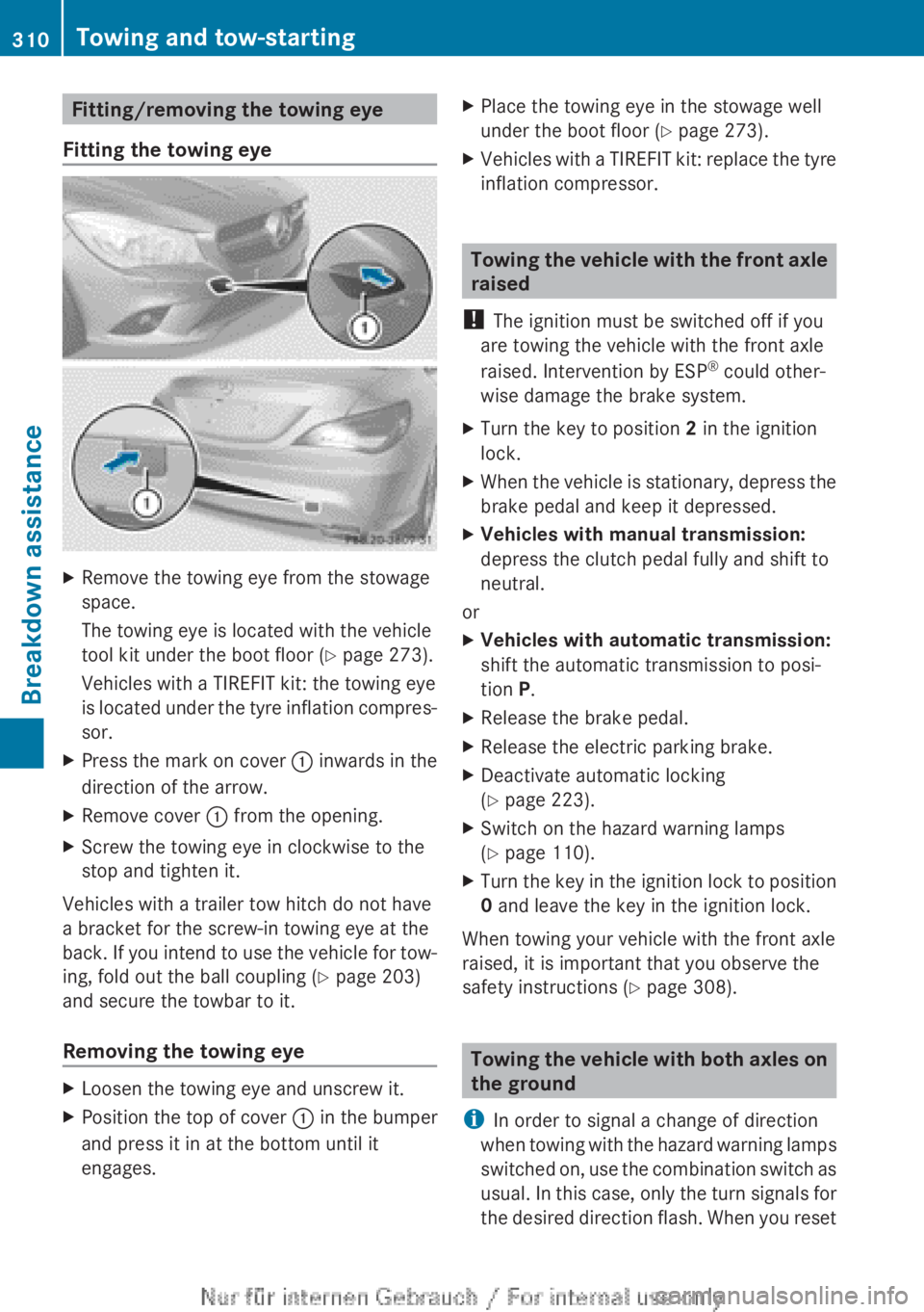
Fitting/removing the towing eye
Fitting the towing eyeXRemove the towing eye from the stowage
space.
The towing eye is located with the vehicle
tool kit under the boot floor ( Y page 273).
Vehicles with a TIREFIT kit: the towing eye
is located under the tyre inflation compres-
sor.XPress the mark on cover : inwards in the
direction of the arrow.XRemove cover : from the opening.XScrew the towing eye in clockwise to the
stop and tighten it.
Vehicles with a trailer tow hitch do not have
a bracket for the screw-in towing eye at the
back. If you intend to use the vehicle for tow-
ing, fold out the ball coupling ( Y page 203)
and secure the towbar to it.
Removing the towing eye
XLoosen the towing eye and unscrew it.XPosition the top of cover : in the bumper
and press it in at the bottom until it
engages.XPlace the towing eye in the stowage well
under the boot floor ( Y page 273).XVehicles with a TIREFIT kit: replace the tyre
inflation compressor.
Towing the vehicle with the front axle
raised
! The ignition must be switched off if you
are towing the vehicle with the front axle
raised. Intervention by ESP ®
could other-
wise damage the brake system.
XTurn the key to position 2 in the ignition
lock.XWhen the vehicle is stationary, depress the
brake pedal and keep it depressed.XVehicles with manual transmission:
depress the clutch pedal fully and shift to
neutral.
or
XVehicles with automatic transmission:
shift the automatic transmission to posi-
tion P.XRelease the brake pedal.XRelease the electric parking brake.XDeactivate automatic locking
( Y page 223).XSwitch on the hazard warning lamps
( Y page 110).XTurn the key in the ignition lock to position
0 and leave the key in the ignition lock.
When towing your vehicle with the front axle
raised, it is important that you observe the
safety instructions ( Y page 308).
Towing the vehicle with both axles on
the ground
i In order to signal a change of direction
when towing with the hazard warning lamps
switched on, use the combination switch as
usual. In this case, only the turn signals for
the desired direction flash. When you reset
310Towing and tow-startingBreakdown assistance
Page 313 of 352
the combination switch, the hazard warn-
ing lamps start flashing again.
Vehicles with automatic transmission: the
automatic transmission automatically shifts
to position P when you open the driver's or
front-passenger door or when you remove the
key from the ignition lock. In order to ensure
that the automatic transmission stays in posi-
tion N when towing the vehicle, you must
observe the following points:XMake sure that the vehicle is stationary.XTurn the key to position 2 in the ignition
lock.XDepress and hold the brake pedal.XShift the automatic transmission to posi-
tion N.
Vehicles with manual transmission:
XTurn the key to position 2 in the ignition
lock.XDepress and hold the brake pedal.XDepress the clutch pedal fully and shift to
neutral.
Vehicles with manual or automatic trans-
mission:
XLeave the key in position 2 in the ignition
lock.XRelease the brake pedal.XRelease the electric parking brake.XSwitch on the hazard warning lamps
( Y page 110).
It is important that you observe the safety
instructions when towing away your vehicle
( Y page 308).
Transporting the vehicle
! You may only secure the vehicle by the
wheels, not by parts of the vehicle such as
axle or steering components. Otherwise,
the vehicle could be damaged.
XVehicles with manual transmission:
depress the clutch pedal fully and shift to
neutral.XVehicles with automatic transmission:
turn the key to position 2 in the ignition
lock.XMove the transmission to position N.
As soon as the vehicle is loaded:
XPrevent the vehicle from rolling away by
applying the electric parking brake.XVehicles with manual transmission:
depress the clutch pedal fully and engage
first or reverse gear.XVehicles with automatic transmission:
shift the transmission to position P.XTurn the key to position 0 in the ignition
lock and remove it.XSecure the vehicle.
The towing eyes or trailer tow hitch can be
used to pull the vehicle onto a trailer or trans-
porter if you wish to transport it.
Tow-starting (emergency engine
starting)
! Do not tow-start vehicles with automatic
transmission. You could otherwise damage
the automatic transmission.
Before tow-starting the following conditions
must be fulfilled:
R the battery is connected.
R the engine has cooled down.
R the exhaust system has cooled down.
XSwitch on the hazard warning lamps
( Y page 110).XFit the towing eye ( Y page 310).XSecure the rigid towing bar or the towing
rope.XDepress and hold the brake pedal.XTurn the key to position 2 in the ignition
lock.Towing and tow-starting311Breakdown assistanceZ
Page 314 of 352

XDepress the clutch pedal fully and shift to
neutral.XRelease the brake pedal.XTow-start the vehicle.XDepress the clutch pedal fully and engage
second gear.XRelease the clutch pedal slowly without
depressing the accelerator pedal.
The engine is started.XDepress the clutch pedal fully and shift to
neutral.XStop at a suitable place.XSecure the vehicle by applying the electric
parking brake.XRemove the rigid towing bar or towing rope.XRemove the towing eye ( Y page 310).XSwitch off the hazard warning lamps.
When tow-starting, it is important that you
observe the safety notes (Y page 308) and the
legal requirements in each respective coun-
try.
Electrical fuses
Important safety notes
GWARNING
If you manipulate, bridge or replace a faulty
fuse with a fuse of a higher amperage, the
electric cables could be overloaded. This may
result in a fire. There is a risk of an accident
and injury.
Always replace faulty fuses with specified new
fuses of the correct amperage.
! Only use fuses that have been approved
for Mercedes-Benz vehicles and which
have the correct fuse rating for the system
concerned. Only use fuses marked with an
"S". Components or systems could other-
wise be damaged.
The fuses in your vehicle serve to disconnect
faulty circuits. If a fuse blows, all the compo-
nents on the circuit and their functions will
fail.
Blown fuses must be replaced with fuses of
the same rating, which you can recognise by
the colour and fuse rating. The fuse ratings
are listed in the fuse allocation chart.
If the newly inserted fuse also blows, have the
cause traced and rectified at a qualified spe-
cialist workshop, e.g. a Mercedes-Benz
Service Centre.
Before replacing a fuse
XSecure the vehicle against rolling away
( Y page 162).XSwitch off all electrical consumers.XTurn the key to position 0 in the ignition
lock and remove it ( Y page 145). All indi-
cator lamps in the instrument cluster must
be off.
The fuses are located in various fuse boxes:
R fuse box in the engine compartment on the
left-hand side of the vehicle, when viewed
in the direction of travel
R fuse box in the front-passenger footwell
The fuse allocation chart is on the fuse box in
the front-passenger footwell ( Y page 313).
Fuse box in the engine compartment
GWARNING
When the bonnet is open, and the windscreen
wipers are set in motion, you can be injured
by the wiper linkage. There is a risk of injury.
Always switch off the windscreen wipers and
the ignition before opening the bonnet.
! Make sure that no moisture can enter the
fuse box when the cover is open.
! When closing the cover, make sure that it
is lying correctly on the fuse box. Moisture
seeping in or dirt could otherwise impair
the operation of the fuses.
312Electrical fusesBreakdown assistance
Page 315 of 352

XOpen the bonnet.XRemove any existing moisture from the
fuse box using a dry cloth.XTo open: open clamps ;.XFold cover : up in the direction of the
arrow and remove it.XTo close: check whether the seal is lying
correctly in cover :.XInsert cover : at the back into openings
= on the fuse box.XFold down cover :.XHook clamps ; into the fuse box and
close.XClose the bonnet.Fuse box in the front-passenger foot-
wellXTo open: remove the floormat from the
front-passenger side.XFold out perforated floor covering : in the
direction of the arrow.XTo release cover =, press retaining
clamp ;.XFold out cover = in the direction of the
arrow to the catch.XRemove cover = forwards.
i
Fuse allocation chart ? is located on the
lower right-hand side of cover =.
XTo close: insert cover = on the left-hand
side of the fuse box into the retainer.
Cover = engages in the retainers.XFold down cover = until clamps ; lock
audibly.XFold back perforated floor covering :.Electrical fuses313Breakdown assistanceZ
Page 319 of 352
wheels and tyres for damage. Hidden tyre
damage could also be causing the unusual
handling characteristics. If you find no
signs of damage, have the wheels and tyres
checked at a qualified specialist workshop.
R When parking your vehicle, make sure that
the tyres do not get deformed by the kerb
or other obstacles. If it is necessary to drive
over kerbs, speed humps or similar eleva-
tions, try to do so slowly and at an obtuse
angle. Otherwise, the tyres, particularly the
sidewalls, may be damaged.
Regular checking of wheels and tyres
GWARNING
Damaged tyres can cause tyre inflation pres-
sure loss. As a result, you could lose control
of your vehicle. There is a risk of accident.
Check the tyres regularly for signs of damage
and replace any damaged tyres immediately.
Regularly check the wheels and tyres of your
vehicle for damage at least once a month, as
well as after driving off-road or on rough
roads. Damaged wheels can cause a loss of
tyre pressure. Pay particular attention to
damage such as:
R cuts in the tyres
R punctures
R tears in the tyres
R bulges on tyres
R deformation or severe corrosion on wheels
Regularly check the tyre tread depth and the
condition of the tread across the whole width
of the tyre ( Y page 317). If necessary, turn
the front wheels to full lock in order to inspect
the inner side of the tyre surface.
All wheels must have a valve cap to protect
the valve against dirt and moisture. Do not fit
anything onto the valve other than the stand-
ard valve cap or other valve caps approved by
Mercedes-Benz for your vehicle. Do not fit any
other valve caps or systems, e.g. tyre pres-
sure monitoring systems.
Regularly check the pressure of all the tyres,
particularly prior to long trips. Adjust the tyre
pressure as necessary ( Y page 319).
Observe the notes on the emergency spare
wheel ( Y page 331).
The service life of tyres depends on various
factors, including the following:
R Driving style
R Tyre pressure
R Mileage
Important safety notes on the tyre
tread
GWARNING
Insufficient tyre tread will reduce tyre trac-
tion. The tyre is no longer able to dissipate
water. This means that on wet road surfaces,
the risk of aquaplaning increases, in particular
where speed is not adapted to suit the driving
conditions. There is a risk of accident.
If the tyre pressure is too high or too low, tyres
may exhibit different levels of wear at differ-
ent locations on the tyre tread. Thus, you
should regularly check the tread depth and
the condition of the tread across the entire
width of all tyres.
Minimum tyre tread depth for:
R summer tyres: 3 mm
R M+S tyres: 4 mm
For safety reasons, replace the tyres before
the legally prescribed limit for the minimum
tyre tread depth is reached..
Selecting, fitting and replacing tyres
R Only fit tyres and wheels of the same type
and make.
Exception: it is permissible to fit a different
type or make in the event of a flat tyre.
Observe the "MOExtended tyres (tyres with
Operation317Wheels and tyresZ
Page 323 of 352

iThe tyre pressure values given for low
loads are minimum values which offer you
good ride comfort characteristics.
However, you can also use the values given
for higher loads. These are permissible and
will not adversely affect the running of the
vehicle.
Tyre pressure loss warning system
General notes
While the vehicle is in motion, the tyre pres-
sure loss warning system monitors the set
tyre pressure using the rotational speed of
the wheels. This enables the system to detect
significant pressure loss in a tyre. If the speed
of rotation of a wheel changes as a result of
a loss of pressure, a corresponding warning
message will appear in the multifunction dis-
play.
You can recognise the tyre pressure loss
warning by the Run Flat Indicator
active Restart with OK message which
appears in the Service menu of the multi-
function display. Further information on the
message display can be found under "Restart-
ing the tyre pressure loss warning system"
( Y page 321).
Important safety notes
The tyre pressure warning system does not
warn you of an incorrectly set tyre pressure.
Observe the notes on the recommended tyre
pressure ( Y page 319).
The tyre pressure loss warning does not
replace the need to regularly check the tyre
pressures. An even loss of pressure on sev-
eral tyres at the same time cannot be detec-
ted by the tyre pressure loss warning system.
The tyre pressure monitor is not able to warn
you of a sudden loss of pressure, e.g. if the
tyre is penetrated by a foreign object. In the
event of a sudden loss of pressure, bring the
vehicle to a halt by braking carefully. Avoid
abrupt steering manoeuvres.
The function of the tyre pressure loss warning
system is limited or delayed if:
R snow chains are fitted to your vehicle's
tyres.
R road conditions are wintry.
R you are driving on sand or gravel.
R you adopt a very sporty driving style (cor-
nering at high speeds or driving with high
rates of acceleration).
R you are towing a very heavy or large trailer.
R you are driving with a heavy load (in the
vehicle or on the roof).
Restarting the tyre pressure loss warn-
ing system
Restart the tyre pressure loss warning system
if you have:
R changed the tyre pressure
R changed the wheels or tyres
R fitted new wheels or tyres
XBefore restarting, make sure that the tyre
pressures are set properly on all four tyres
for the respective operating conditions.
The recommended tyre pressures can be
found in the table on the fuel filler flap.
The tyre pressure loss warning system can
only give reliable warnings if you have set
the correct tyre pressure. If an incorrect
tyre pressure is set, these incorrect values
will be monitored.XObserve the notes in the section on tyre
pressures ( Y page 319).XMake sure that the key is in position 2 in
the ignition lock ( Y page 145).XPress = or ; on the steering wheel
to select the Service menu.XPress the 9 or : button to select
Tyre press. .XPress the a button.
The Run Flat Indicator active
Restart with OK message appears in the
multifunction display.Tyre pressure321Wheels and tyresZ
Page 325 of 352
pressure warning lamp to inform you of the
malfunction by flashing for approximately one
minute and then remaining lit. When the fault
has been rectified, the tyre pressure warning
lamp goes out after you have driven for a few
minutes.
The tyre pressure values indicated by the on-
board computer may differ from those meas-
ured at a filling station using a pressure
gauge. The tyre pressures shown by the on-
board computer refer to those measured at
sea level. At high altitudes, the tyre pressure
values indicated by a pressure gauge are
higher than those shown by the on-board
computer. In this case, do not reduce the tyre
pressures.
The operation of the tyre pressure monitor
can be affected by interference from radio
transmitting equipment (e.g. radio head-
phones, two-way radios) that may be being
operated in or near the vehicle.
Checking the tyre pressure electroni-
callyXMake sure that the key is in position 2 in
the ignition lock ( Y page 145).XPress the = or ; button on the steer-
ing wheel to select the Service menu.XPress the 9 or : button to select
Tyre pressure .XPress the a button.
The current tyre pressure for each wheel
will be displayed in the multifunction dis-
play.
If the vehicle has been parked for over
20 minutes, the Tyre pressures will be
displayed after a few minutes of
driving message appears.
After a teach-in period, the tyre pressure
monitor automatically recognises new
wheels or new sensors. As long as a clear
allocation of the tyre pressure values to the
individual wheels is not possible, the Tyre
pressure monitor active display mes-
sage is shown instead of the tyre pressure
display. The tyre pressures are already being
monitored.
i If an emergency spare wheel is fitted, the
system may continue to show the tyre pres-
sure of the wheel that has been removed
for a few minutes. If this occurs, note that
the value displayed for the position where
the spare wheel is fitted is not the same as
the current tyre pressure of the emergency
spare wheel.
Warning messages of the tyre pressure
monitor
If the tyre pressure monitor detects a pres-
sure loss in one or more tyres, a warning mes-
sage is shown in the multifunction display and
the yellow tyre pressure monitor warning light
comes on.
R If the Please correct tyre pressure
message appears in the multifunction dis-
play, the tyre pressure in at least one tyre
is too low and must be corrected at the next
opportunity.
R If the Tyre pressure Check tyre(s)
message appears in the multifunction dis-
play, the tyre pressure in one or more tyres
has dropped significantly and the tyres
must be checked.
R If the Tyre pressure Caution, tyre
defect message appears in the multifunc-
tion display, the tyre pressure in one or
more tyres has dropped suddenly and the
tyres must be checked.
Observe the instructions and safety notes in
the display messages in the "Tyres" section
( Y page 248).
i If the wheel positions on the vehicle are
interchanged, the tyre pressures may be
displayed for the wrong positions for a
short time. This is rectified after a few
minutes of driving and the tyre pressures
are displayed for the correct positions.
Tyre pressure323Wheels and tyresZ