2013 MERCEDES-BENZ CLA-CLASS light
[x] Cancel search: lightPage 201 of 352
Indicator and warning display
Blind Spot Assist is not active at speeds below
approximately 30 km/h. Vehicles in the mon-
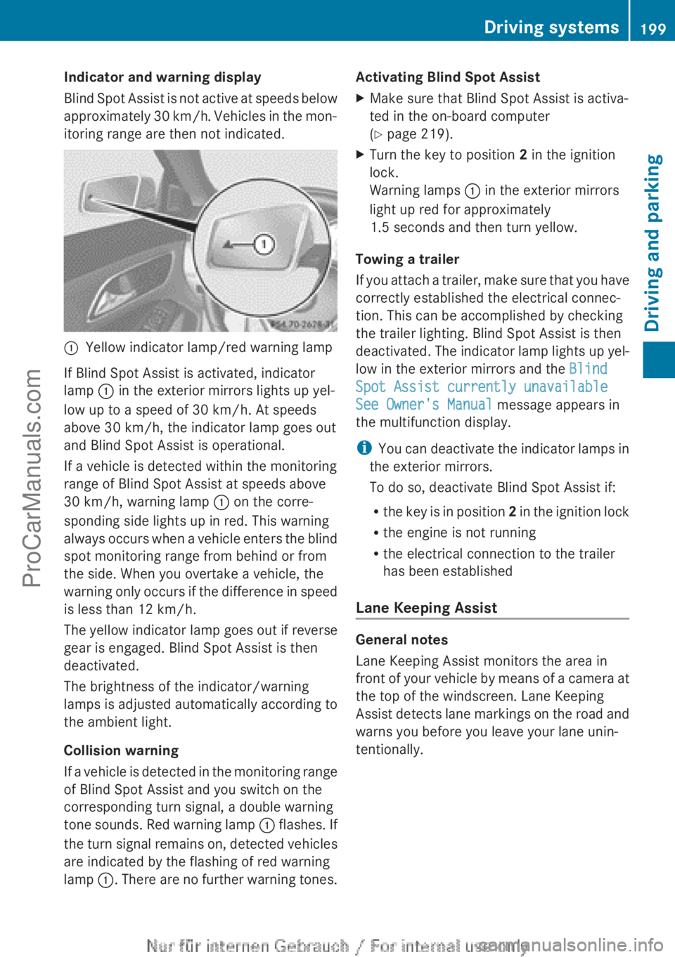
itoring range are then not indicated.:Yellow indicator lamp/red warning lamp
If Blind Spot Assist is activated, indicator
lamp : in the exterior mirrors lights up yel-
low up to a speed of 30 km/h. At speeds
above 30 km/h, the indicator lamp goes out
and Blind Spot Assist is operational.
If a vehicle is detected within the monitoring
range of Blind Spot Assist at speeds above
30 km/h, warning lamp : on the corre-
sponding side lights up in red. This warning
always occurs when a vehicle enters the blind
spot monitoring range from behind or from
the side. When you overtake a vehicle, the
warning only occurs if the difference in speed
is less than 12 km/h.
The yellow indicator lamp goes out if reverse
gear is engaged. Blind Spot Assist is then
deactivated.
The brightness of the indicator/warning
lamps is adjusted automatically according to
the ambient light.
Collision warning
If a vehicle is detected in the monitoring range
of Blind Spot Assist and you switch on the
corresponding turn signal, a double warning
tone sounds. Red warning lamp : flashes. If
the turn signal remains on, detected vehicles
are indicated by the flashing of red warning
lamp :. There are no further warning tones.
Activating Blind Spot AssistXMake sure that Blind Spot Assist is activa-
ted in the on-board computer
( Y page 219).XTurn the key to position 2 in the ignition
lock.
Warning lamps : in the exterior mirrors
light up red for approximately
1.5 seconds and then turn yellow.
Towing a trailer
If you attach a trailer, make sure that you have
correctly established the electrical connec-
tion. This can be accomplished by checking
the trailer lighting. Blind Spot Assist is then
deactivated. The indicator lamp lights up yel-
low in the exterior mirrors and the Blind
Spot Assist currently unavailable
See Owner's Manual message appears in
the multifunction display.
i You can deactivate the indicator lamps in
the exterior mirrors.
To do so, deactivate Blind Spot Assist if:
R the key is in position 2 in the ignition lock
R the engine is not running
R the electrical connection to the trailer
has been established
Lane Keeping Assist
General notes
Lane Keeping Assist monitors the area in
front of your vehicle by means of a camera at
the top of the windscreen. Lane Keeping
Assist detects lane markings on the road and
warns you before you leave your lane unin-
tentionally.
Driving systems199Driving and parkingZProCarManuals.com
Page 206 of 352
Before you can tow a trailer with your vehicle,
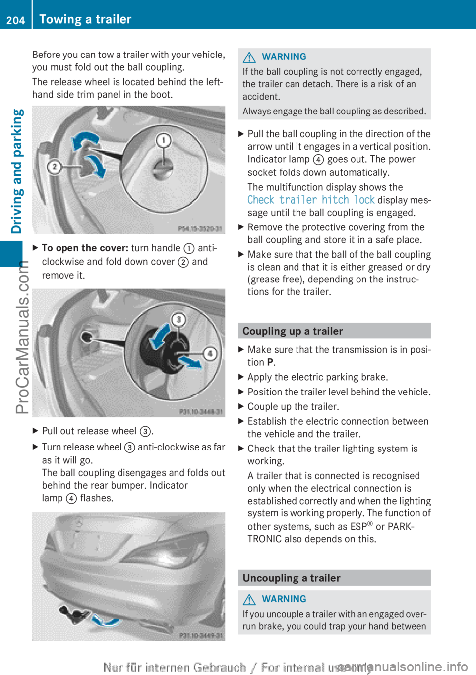
you must fold out the ball coupling.
The release wheel is located behind the left-
hand side trim panel in the boot.XTo open the cover: turn handle : anti-
clockwise and fold down cover ; and
remove it.XPull out release wheel =.XTurn release wheel = anti-clockwise as far
as it will go.
The ball coupling disengages and folds out
behind the rear bumper. Indicator
lamp ? flashes.GWARNING
If the ball coupling is not correctly engaged,
the trailer can detach. There is a risk of an
accident.
Always engage the ball coupling as described.
XPull the ball coupling in the direction of the
arrow until it engages in a vertical position.
Indicator lamp ? goes out. The power
socket folds down automatically.
The multifunction display shows the
Check trailer hitch lock display mes-
sage until the ball coupling is engaged.XRemove the protective covering from the
ball coupling and store it in a safe place.XMake sure that the ball of the ball coupling
is clean and that it is either greased or dry
(grease free), depending on the instruc-
tions for the trailer.
Coupling up a trailer
XMake sure that the transmission is in posi-
tion P.XApply the electric parking brake.XPosition the trailer level behind the vehicle.XCouple up the trailer.XEstablish the electric connection between
the vehicle and the trailer.XCheck that the trailer lighting system is
working.
A trailer that is connected is recognised
only when the electrical connection is
established correctly and when the lighting
system is working properly. The function of
other systems, such as ESP ®
or PARK-
TRONIC also depends on this.
Uncoupling a trailer
GWARNING
If you uncouple a trailer with an engaged over-
run brake, you could trap your hand between
204Towing a trailerDriving and parking
ProCarManuals.com
Page 208 of 352
XPress the ball coupling in the direction of
the arrow until it engages behind the
bumper.
Indicator lamp ? goes out and the mes-
sage in the multifunction display disap-
pears.
Trailer power supply
! You can connect accessories with a
power rating of up to 240 W to the perma-
nent power supply and with a power rating
of up to 180 W to the power supply that is
switched on via the ignition lock.
The trailer battery may not be charged from
the power supply.
XTo switch the connected power supply
on or off: turn the key in the ignition lock
to position 2 or 0 respectively.
When it leaves the factory, your vehicle's
trailer socket is equipped with a permanent
power supply and a power supply that is
switched on via the ignition lock.
The permanent power supply is supplied via
trailer socket pin 9.
The power supply that is switched on via the
ignition lock is supplied via trailer socket pin
10.
The trailer's permanent power supply is
switched off in the event of low vehicle supply
voltage and after six hours at the latest.
You can find more information about instal-
ling the trailer electrics at a qualified special-
ist workshop.
Bulb failure indicator for LED lamps
i If LED lamps are fitted in the trailer, an
error message may appear in the multi-
function display even if there is no fault. The
reason for the error message could be that
the current has fallen below the minimum
of 50 mA.
To ensure reliable operation of the bulb failure
indicator, each LED chain in the trailer lighting
must be guaranteed a minimum current of
50 mA.
Trailer with 7-pin connector
General notes
Trailers with 7-pin connector: you can
make a connection to the 13-pin connector
on the ball coupling using an adapter plug or,
if necessary, an adapter cable. Both can be
obtained in a qualified specialist workshop.
Fitting the adapter
! Make sure that there is sufficient cable
play so that the cable cannot become
detached when cornering.
! Remove the installed adapter cable
before folding in the ball coupling. Other-
wise, damage may occur to the rear
bumper and the adapter cable.
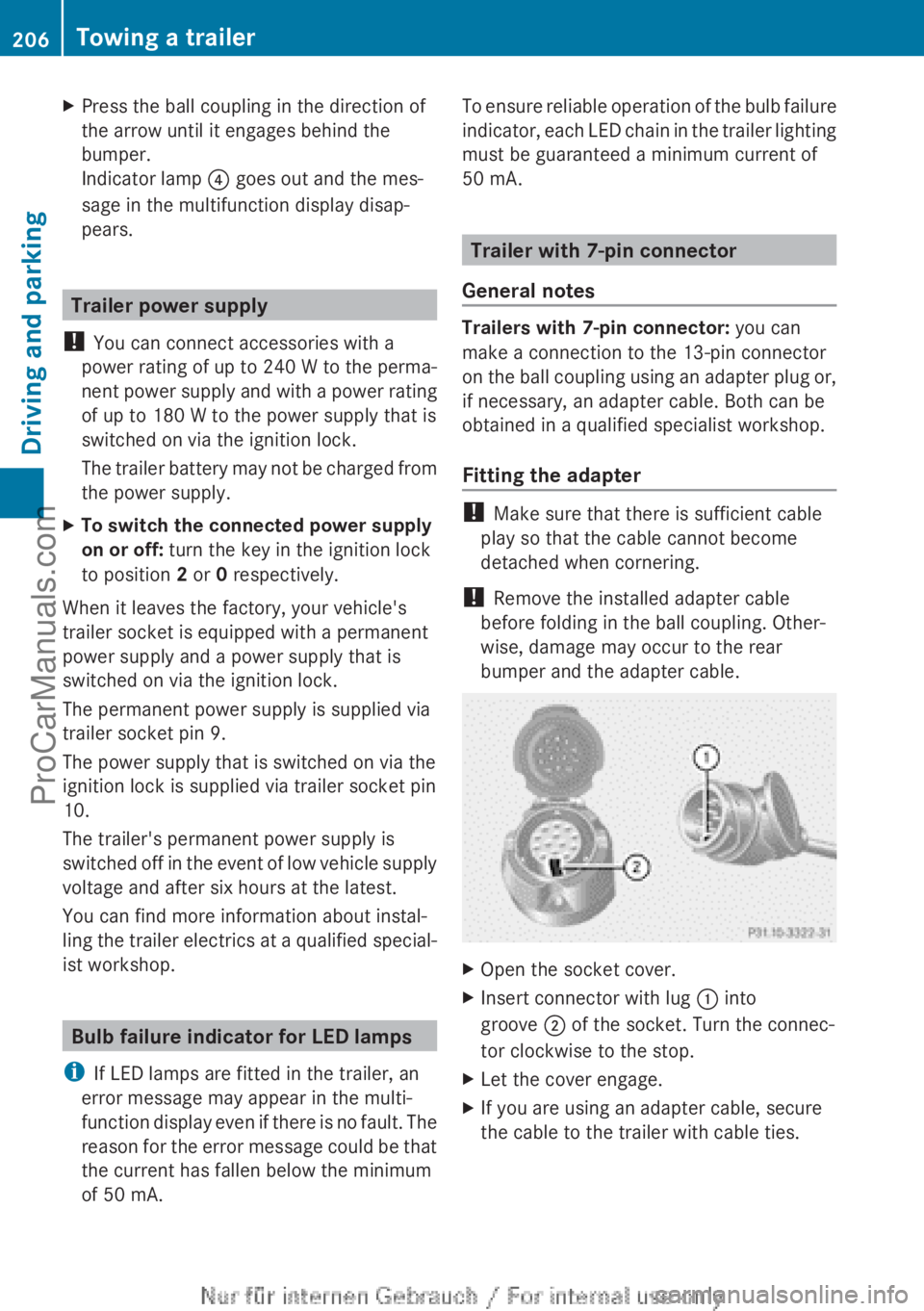
XOpen the socket cover.XInsert connector with lug : into
groove ; of the socket. Turn the connec-
tor clockwise to the stop.XLet the cover engage.XIf you are using an adapter cable, secure
the cable to the trailer with cable ties.206Towing a trailerDriving and parking
ProCarManuals.com
Page 210 of 352

Useful information
i This Owner's Manual describes all mod-
els, series and optional equipment for your
vehicle that were available at the time of
going to press. National variations are pos-
sible. Note that your vehicle may not be
equipped with all of the functions descri-
bed. This is also the case for systems and
functions relevant to safety.
i Read the information on qualified special-
ist workshops: ( Y page 24).
Important safety notes
GWARNING
Operating the integrated information systems
and communications equipment in the vehicle
while driving will distract you from traffic con-
ditions. You could then lose control of the
vehicle. There is a risk of an accident.
Only operate these devices if road traffic con-
ditions permit. If you are unsure about the
surrounding conditions, pull over to a safe
location and make entries only while the vehi-
cle is stationary.
GWARNING
If the instrument cluster has failed or mal-
functioned, you may not recognise function
restrictions relevant to safety. The operating
safety of your vehicle may be impaired. There
is a risk of an accident.
Drive on carefully. Have the vehicle checked
at a qualified specialist workshop immedi-
ately.
You must observe the legal requirements for
the country in which you are currently driving
when operating the on-board computer.
The on-board computer only shows messages
or warnings from certain systems in the mul-
tifunction display. You should therefore make
sure your vehicle is operating safely at all
times. Otherwise, a vehicle that is not oper-
ating safely may cause an accident.
For an overview, see the instrument panel
illustration ( Y page 30).
Displays and operation
Instrument cluster lighting
The lighting in the instrument cluster, in the
displays and the controls in the vehicle inte-
rior can be adjusted using the brightness con-
trol knob.
The brightness control knob is on the bottom
left of the instrument cluster ( Y page 30).
XTurn the brightness control knob clockwise
or anti-clockwise.
If the light switch is set to Ã, T or
L , the brightness is dependant upon
the brightness of the ambient light.
i The light sensor in the instrument cluster
automatically controls the brightness of
the multifunction display.
In daylight, the displays in the instrument
cluster are not illuminated.
Coolant temperature gauge
GWARNING
If you open the bonnet while the engine is
overheating or while there is a fire in the
engine compartment, you could come into
contact with hot gases or other leaking
service products. There is a danger of injury.
Allow an overheating engine to cool down
before opening the bonnet. If there is a fire in
the engine compartment, leave the bonnet
closed and notify the fire brigade.
The coolant temperature gauge is in the
instrument cluster on the right-hand side.
Under normal operating conditions and with
the specified coolant level, the coolant tem-
perature may rise to 120 †.
208Displays and operationOn-board computer and displays
ProCarManuals.com
Page 211 of 352
At high outside temperatures and when driv-
ing uphill, the coolant temperature may rise
to the end of the scale.
Rev counter
! Do not drive in the overrevving range.
Doing so will damage the engine.
The red band in the rev counter indicates the
engine's overrevving range.
The fuel supply is interrupted to protect the
engine when the red band is reached.
Outside temperature display
You should pay special attention to road con-
ditions when temperatures are around the
freezing point.
The outside temperature display is in the mul-
tifunction display.
Changes in the outside temperature are dis-
played after a short delay.
Speedometer with segments
The speedometer is divided into segments on
vehicles with DISTRONIC PLUS.
The segments in the speedometer indicate
which speed range is available.
R Cruise control activated ( Y page 168):
The segments light up from the stored
speed to the maximum speed.
R Variable SPEEDTRONIC activated
( Y page 171):
The segments light up from the start of the
scale to the selected limit speed.
R DISTRONIC PLUS activated ( Y page 173):
One or two segments in the set speed
range light up.
R DISTRONIC PLUS detects a vehicle in front:
The segments between the speed of the
vehicle in front and the stored speed light
up.
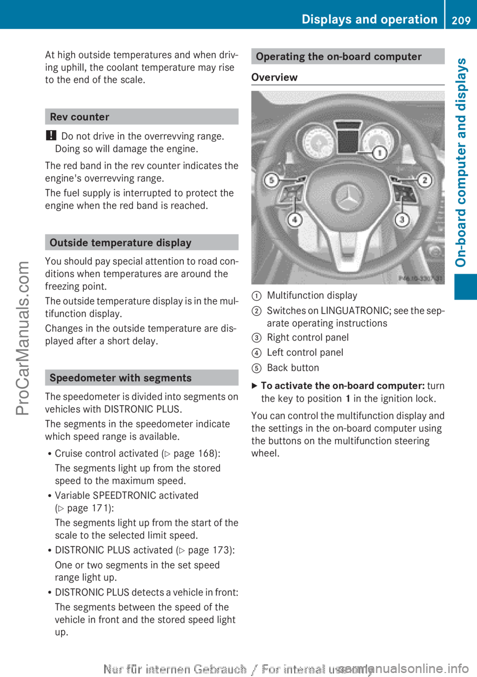
Operating the on-board computer
Overview:Multifunction display;Switches on LINGUATRONIC; see the sep-
arate operating instructions=Right control panel?Left control panelABack buttonXTo activate the on-board computer: turn
the key to position 1 in the ignition lock.
You can control the multifunction display and
the settings in the on-board computer using
the buttons on the multifunction steering
wheel.
Displays and operation209On-board computer and displaysZProCarManuals.com
Page 213 of 352
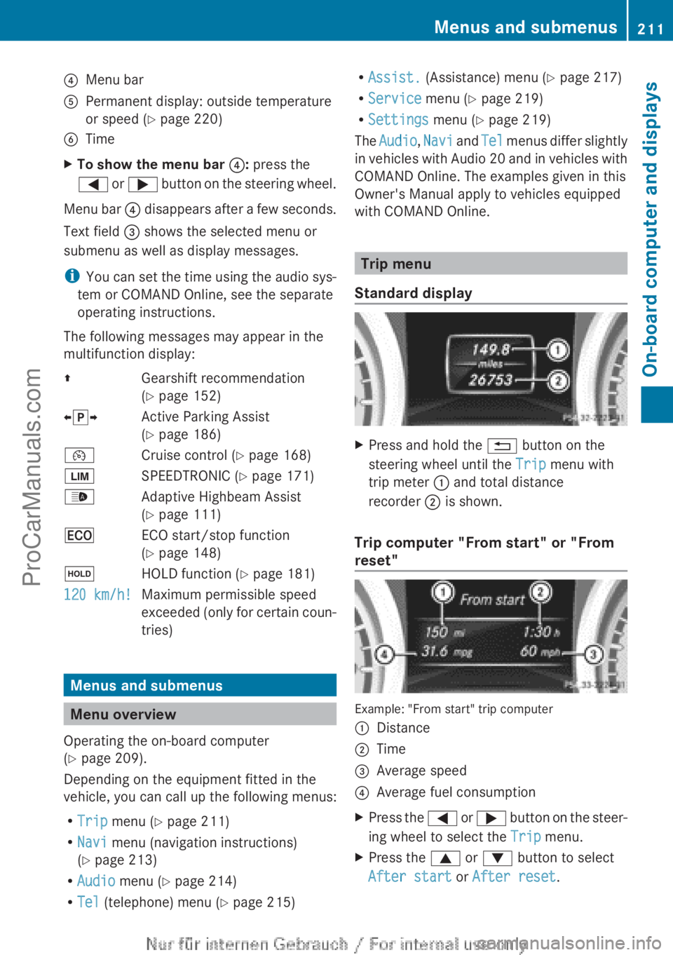
?Menu barAPermanent display: outside temperature
or speed ( Y page 220)BTimeXTo show the menu bar ?: press the
= or ; button on the steering wheel.
Menu bar ? disappears after a few seconds.
Text field = shows the selected menu or
submenu as well as display messages.
i You can set the time using the audio sys-
tem or COMAND Online, see the separate
operating instructions.
The following messages may appear in the
multifunction display:
ZGearshift recommendation
( Y page 152)Xj YActive Parking Assist
( Y page 186)¯Cruise control ( Y page 168)ÈSPEEDTRONIC ( Y page 171)_Adaptive Highbeam Assist
( Y page 111)¤ECO start/stop function
( Y page 148)ëHOLD function ( Y page 181)120 km/h!Maximum permissible speed
exceeded (only for certain coun-
tries)
Menus and submenus
Menu overview
Operating the on-board computer
( Y page 209).
Depending on the equipment fitted in the
vehicle, you can call up the following menus:
R Trip menu ( Y page 211)
R Navi menu (navigation instructions)
( Y page 213)
R Audio menu ( Y page 214)
R Tel (telephone) menu ( Y page 215)
R
Assist. (Assistance) menu ( Y page 217)
R Service menu (Y page 219)
R Settings menu (Y page 219)
The Audio , Navi and Tel menus differ slightly
in vehicles with Audio 20 and in vehicles with
COMAND Online. The examples given in this
Owner's Manual apply to vehicles equipped
with COMAND Online.
Trip menu
Standard display
XPress and hold the % button on the
steering wheel until the Trip menu with
trip meter : and total distance
recorder ; is shown.
Trip computer "From start" or "From
reset"
Example: "From start" trip computer
:Distance;Time=Average speed?Average fuel consumptionXPress the = or ; button on the steer-
ing wheel to select the Trip menu.XPress the 9 or : button to select
After start or After reset .Menus and submenus211On-board computer and displaysZProCarManuals.com
Page 220 of 352
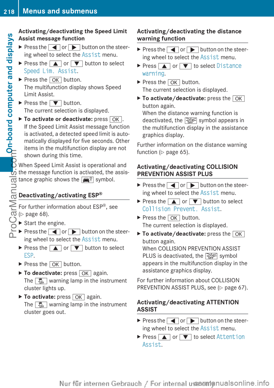
Activating/deactivating the Speed Limit
Assist message functionXPress the = or ; button on the steer-
ing wheel to select the Assist menu.XPress the 9 or : button to select
Speed Lim. Assist .XPress the a button.
The multifunction display shows Speed
Limit Assist.XPress the : button.
The current selection is displayed.XTo activate or deactivate: press a.
If the Speed Limit Assist message function
is activated, a detected speed limit is auto-
matically displayed for five seconds. Other
items in the multifunction display are not
shown during this time.
When Speed Limit Assist is operational and
the message function is activated, the assis-
tance graphic shows the Ä symbol.
Deactivating/activating ESP ®
For further information about ESP
®
, see
( Y page 68).
XStart the engine.XPress the = or ; button on the steer-
ing wheel to select the Assist menu.XPress the 9 or : button to select
ESP .XPress the a button.XTo deactivate: press a again.
The å warning lamp in the instrument
cluster lights up.XTo activate: press a again.
The å warning lamp in the instrument
cluster goes out.Activating/deactivating the distance
warning functionXPress the = or ; button on the steer-
ing wheel to select the Assist menu.XPress 9 or : to select Distance
warning .XPress the a button.
The current selection is displayed.XTo activate/deactivate: press the a
button again.
When the distance warning function is
deactivated, the æ symbol appears in
the multifunction display in the assistance
graphics display.
Further information on the distance warning
function ( Y page 65).
Activating/deactivating COLLISION
PREVENTION ASSIST PLUS
XPress the = or ; button on the steer-
ing wheel to select the Assist menu.XPress the 9 or : button to select
Collision Prevent. Assist .XPress the a button.
The current selection is displayed.XTo activate/deactivate: press the a
button again.
When COLLISION PREVENTION ASSIST
PLUS is deactivated, the æ symbol
appears in the multifunction display in the
assistance graphics display.
For further information about COLLISION
PREVENTION ASSIST PLUS, see (Y page 67).
Activating/deactivating ATTENTION
ASSIST
XPress the = or ; button on the steer-
ing wheel to select the Assist menu.XPress 9 or : to select Attention
Assist .218Menus and submenusOn-board computer and displays
ProCarManuals.com
Page 221 of 352
XPress the a button.
The current selection is displayed.XTo activate/deactivate: press the a
button again.
When ATTENTION ASSIST ( Y page 195) is
deactivated, the é symbol appears in
the multifunction display in the assistance
graphics display.
Activating/deactivating Blind Spot
Assist
XPress the = or ; button on the steer-
ing wheel to select the Assist menu.XPress 9 or : to select Blind Spot
Asst. .XPress the a button.
The current selection is displayed.XTo activate/deactivate: press the a
button again.
For further information about Blind Spot
Assist, see ( Y page 197).
When the Blind Spot Assist: Sensors
deactivated message is shown, the radar
sensors are deactivated.
XSwitch on the radar sensor system
( Y page 223).
Activating/deactivating Lane Keeping
Assist
XPress the = or ; button on the steer-
ing wheel to select the Assist menu.XPress 9 or : on the steering wheel
to select Lane Keeping Assist .XPress the a button.
The current selection is displayed.XPress a to confirm.XPress the : or 9 button to set Off,
Standard or Adaptive .XPress the a button to save the setting.
When Lane Keeping Assist ( Y page 199) is
activated, the multifunction display in theassistance graphic shows the lane mark-
ings in green.
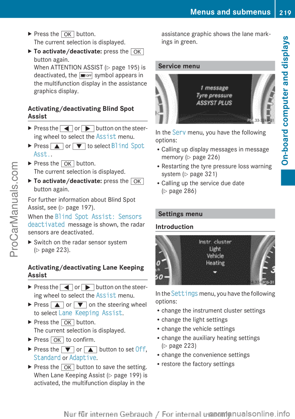
Service menu
In the Serv menu, you have the following
options:
R Calling up display messages in message
memory ( Y page 226)
R Restarting the tyre pressure loss warning
system ( Y page 321)
R Calling up the service due date
( Y page 286)
Settings menu
Introduction
In the Settings menu, you have the following
options:
R change the instrument cluster settings
R change the light settings
R change the vehicle settings
R change the auxiliary heating settings
( Y page 223)
R change the convenience settings
R restore the factory settings
Menus and submenus219On-board computer and displaysZProCarManuals.com