2013 MERCEDES-BENZ B-CLASS SPORTS seats
[x] Cancel search: seatsPage 233 of 336
Useful information
i This Operator's Manual describes all
models and all standard and optional
equipment of your vehicle available at the
time of publication of the Operator's
Manual. Country-specific differences are
possible. Please note that your vehicle may
not be equipped with all features
described. This also applies to safety-
related systems and functions.
i Please read the information on qualified
specialist workshops (Y page 23).Loading guidelines
G
WARNING
Always faste nitems being carried as securely
as possible using cargo tie-down rings and
fastening materials appropriate for the weight
and size of the load.
In an accident, durin ghard braking or sudden
maneuvers, loose items will be thrown around
inside the vehicle .This can cause injury to
vehicle occupants unless the items are
securely fastened in the vehicle.
To help avoid personal injury during a collision
or sudden maneuver, exercise care when
transporting cargo. Do not pile luggage or
cargo higher than the seat backrests.
Never drive a vehicle with the tailgate open.
Deadly carbon monoxide (CO) gases may
enter vehicle interior resulting in
unconsciousness and death.
The handling characteristics of a laden
vehicle are dependent on the distribution of
the load within the vehicle. For this reason,
you should observe the following notes when
transporting a load:
R when transporting a load, never exceed the
maximum permissible gross vehicle weight
or the gross axle weight rating of the
vehicle (including occupants). The values are specified on the vehicle identification
plate on the B-pillar of the driver's door.
R position heavy loads as far forwards as
possible and as low down in the cargo
compartmenta s possible.
R the load must not protrude above the upper
edge of the seat backrests.
R always place the load against the rear or
front seat backrests. Make sure that the
seat backrests are securely locked into
place.
R hook in the cargo net when loading.
R the maximum load capacity of the stowage
well under the cargo compartment floor is
55 lbs (25 kg).
R always place the load behind unoccupied
seats if possible.
R secure the load with sufficiently strong and
wear-resistant tie-downs. Pad sharp edges
for protection.
! Do not position the load on one part of the
folding cargo compartment floor only. The
maximum load capacity of the folding cargo
compartment floor is 220 lbs (100 kg).
Distribute the weight evenly to avoid
damaging the cargo compartment floor.
Place a solid board under the load if
necessary. Please note that the load on the
cargo compartment floor will be increased
when the load is lashed down. Stowage areas
Stowage space
Important safety notes G
WARNING
To help avoid personal injury during a collision
or sudden maneuver, exercise care when
storing objects in the vehicle. Put luggage or
cargo in the cargo compartment if possible.
Do not pile luggage or cargo higher than the
seat backrests. 230
Stowage areasStowage and features
Page 237 of 336
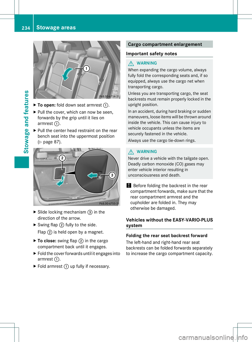
X
To open: fold down sea tarmrest :.
X Pull the cover, which can now be seen,
forwards by the grip until it lies on
armrest :.
X Pull the center head restraint on the rear
bench seat into the uppermost position
(Y page 87). X
Slide locking mechanism =in the
direction of the arrow.
X Swing flap ;fully to the side.
Flap ;is held open by a magnet.
X To close: swing flap ;in the cargo
compartment back until it engages.
X Fold the cover forwards until it engages into
armrest :.
X Fold armrest :up fully if necessary. Cargo compartment enlargement
Important safety notes G
WARNING
When expanding the cargo volume, always
fully fold the corresponding seats and, if so
equipped, always use the cargo net when
transporting cargo.
Unless you are transporting cargo, the seat
backrests must remai nproperly locked in the
upright position.
In an accident, during hard braking or sudden
maneuvers, loose items will be thrown around
inside the vehicle. This can cause injury to
vehicle occupants unless the items are
securely fastened in the vehicle.
Always use the cargo tie-dow nrings. G
WARNING
Never drive a vehicle with the tailgate open.
Deadly carbo nmonoxide (CO) gases may
enter vehicle interior resulting in
unconsciousness and death.
! Before folding the backrest in the rear
compartment forwards, make sure that the
rear compartment armrest and the
cupholder are folded in. They may
otherwise be damaged.
Vehicles without the EASY-VARIO-PLUS
system Folding the rear seat backrest forward
The left-hand and right-hand rear seat
backrests can be folded forwards separately
to increase the cargo compartment capacity.234
Stowage areasStowage and features
Page 240 of 336
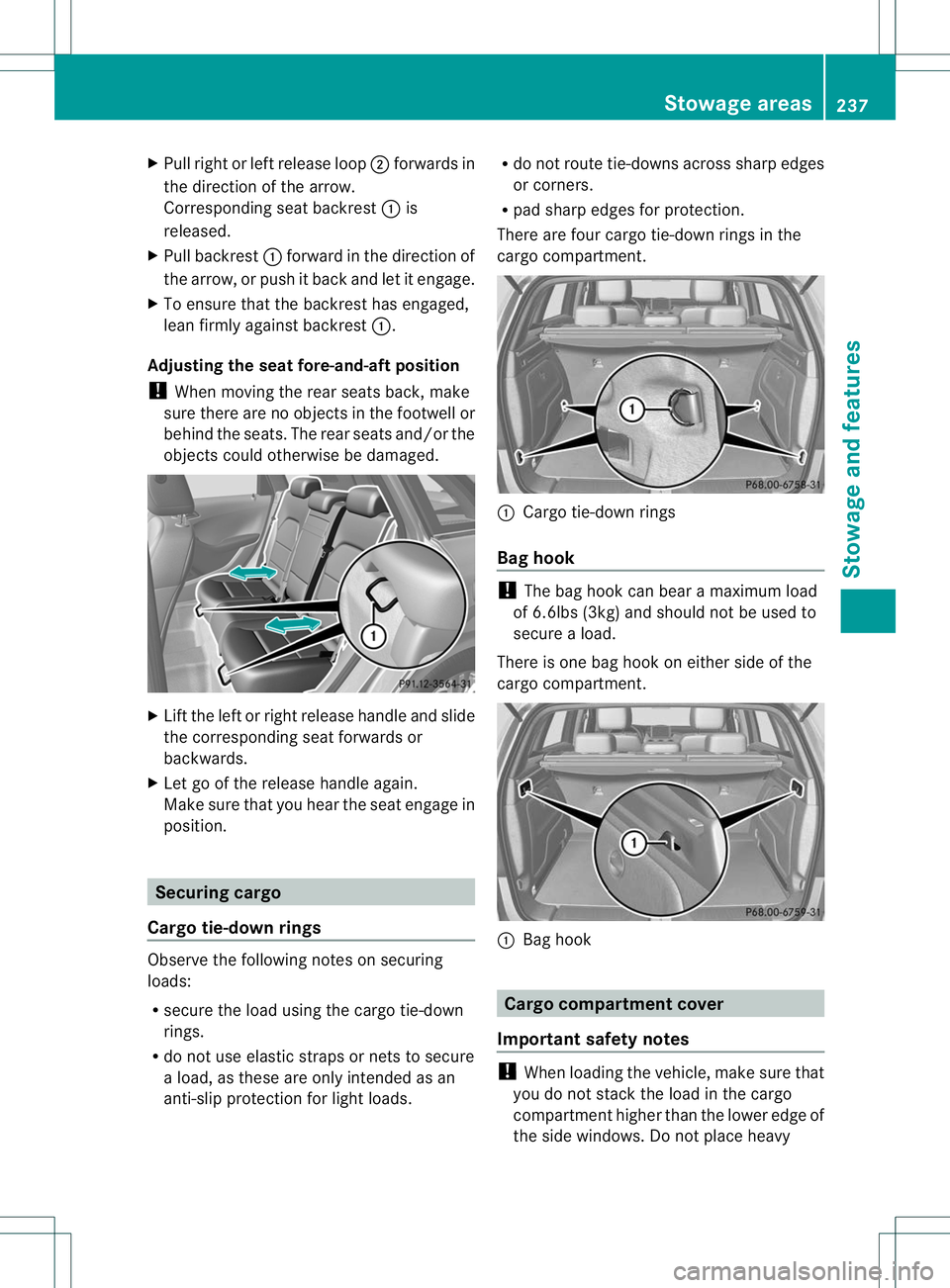
X
Pull right or left release loop ;forwards in
the direction of the arrow.
Corresponding seat backrest :is
released.
X Pull backrest :forward in the direction of
the arrow, or push it back and let it engage.
X To ensure that the backrest has engaged,
lean firmly against backrest :.
Adjusting the seat fore-and-aft position
! When moving the rear seats back, make
sure there are no objects in the footwell or
behind the seats. The rear seats and/or the
objects could otherwise be damaged. X
Lift the left or right release handle and slide
the corresponding seat forwards or
backwards.
X Let go of the release handle again.
Make sure that you hear the seat engage in
position. Securing cargo
Cargo tie-down rings Observe the following notes on securing
loads:
R
secure the load using the cargo tie-down
rings.
R do not use elastic straps or nets to secure
a load, as these are only intended as an
anti-slip protection for light loads. R
do not route tie-downs across sharp edges
or corners.
R pad sharp edges for protection.
There are four cargo tie-down rings in the
cargo compartment. :
Cargo tie-down rings
Bag hook !
The bag hook can bear a maximum load
of 6.6lbs (3kg) and should not be used to
secure a load.
There is one bag hook on either side of the
cargo compartment. :
Bag hook Cargo compartment cover
Important safety notes !
When loading the vehicle, make sure that
you do not stack the load in the cargo
compartment higher than the lower edge of
the side windows. Do not place heavy Stowage areas
237Stowage and features Z
Page 282 of 336
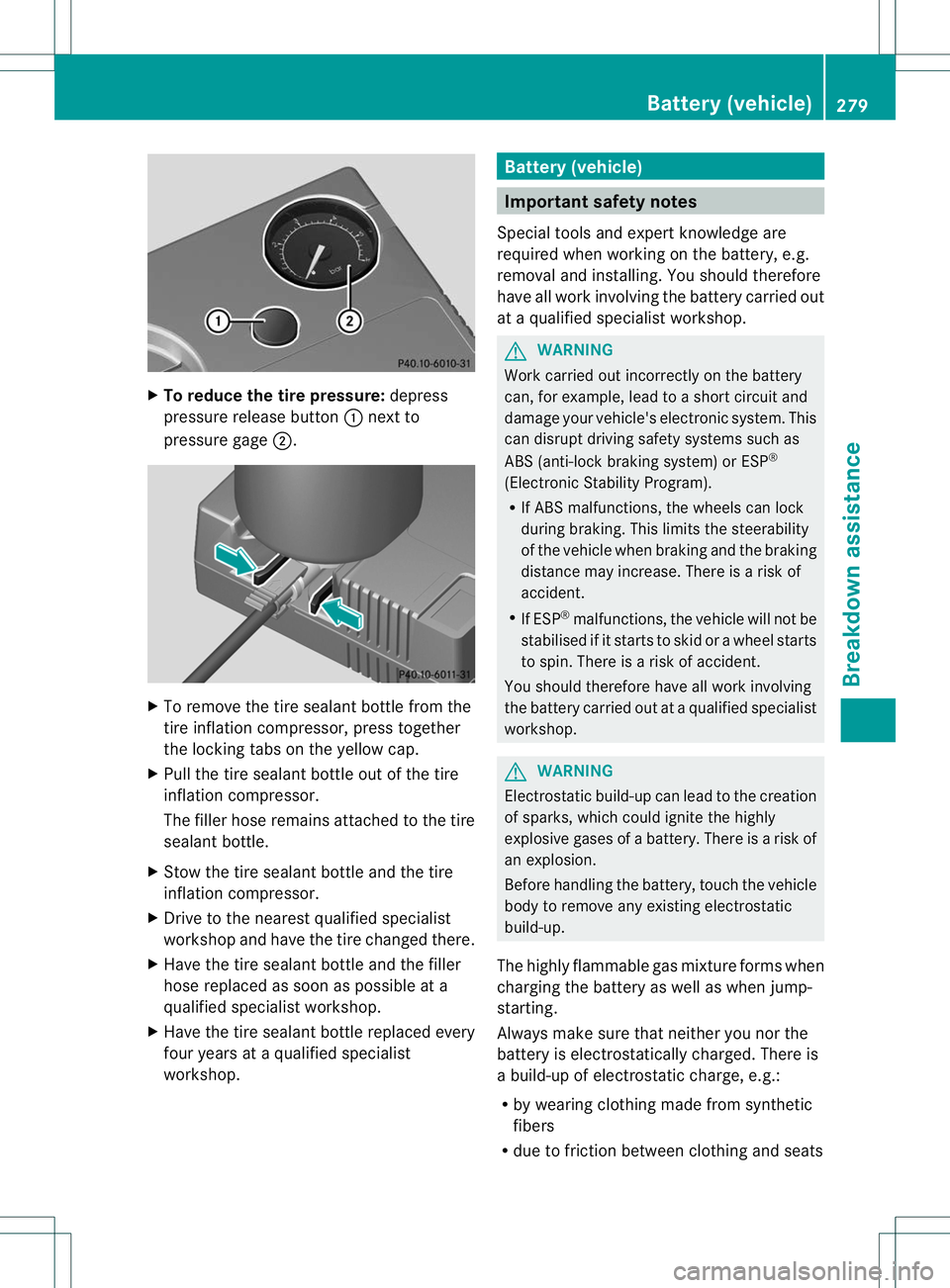
X
To reduce the tire pressure: depress
pressure release button :next to
pressure gage ;. X
To remove the tire sealant bottle from the
tire inflation compressor, press together
the locking tabs on the yellow cap.
X Pull the tire sealant bottle outoft he tire
inflation compressor.
The filler hose remains attached to the tire
sealant bottle.
X Stow the tire sealant bottle and the tire
inflation compressor.
X Drive to the nearest qualified specialist
workshop and have the tire changed there.
X Have the tire sealant bottle and the filler
hose replaced as soon as possible at a
qualified specialist workshop.
X Have the tire sealant bottle replaced every
four years at a qualified specialist
workshop. Battery (vehicle)
Important safety notes
Special tools and expert knowledge are
required when working on the battery, e.g.
removal and installing. You should therefore
have all work involving the battery carried out
at a qualified specialist workshop. G
WARNING
Work carried out incorrectly on the battery
can, for example, lead to a short circuit and
damage your vehicle's electronic system. This
can disrupt driving safety systems such as
ABS (anti-lock braking system) or ESP ®
(Electronic Stability Program).
R If ABS malfunctions, the wheels can lock
during braking. This limits the steerability
of the vehicle when braking and the braking
distance may increase. There is a risk of
accident.
R If ESP ®
malfunctions, the vehicle will not be
stabilised if it starts to skid or a wheel starts
to spin. There is a risk of accident.
You should therefore have all work involving
the battery carried out at a qualified specialist
workshop. G
WARNING
Electrostatic build-up can lead to the creation
of sparks, which could ignite the highly
explosive gases of a battery. There is a risk of
an explosion.
Before handling the battery, touch the vehicle
body to remove any existing electrostatic
build-up.
The highly flammable gas mixture forms when
charging the battery as well as when jump-
starting.
Always make sure that neither you nor the
battery is electrostatically charged. There is
a build-up of electrostatic charge, e.g.:
R by wearing clothing made from synthetic
fibers
R due to friction between clothing and seats Battery (vehicle)
279Breakdown assistance Z
Page 299 of 336
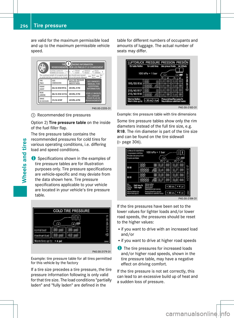
are valid for the maximum permissible load
and up to the maximum permissible vehicle
speed.
:
Recommended tire pressures
Option 2) Tire pressure table on the inside
of the fuel fille rflap.
The tire pressure table contains the
recommended pressures for cold tires for
various operating conditions, i.e. differing
load and speed conditions.
i Specifications shown in the examples of
tire pressure tables are for illustration
purposes only. Tire pressure specifications
are vehicle-specific and may deviate from
the data shown here. Tire pressure
specifications applicable to your vehicle
are located in your vehicle's tire pressure
table. Example: tire pressure table for all tires permitted
for this vehicle by the factory
If a tire size precedes a tire pressure, the tire
pressure information followin
gis only valid
for that tire size. The load conditions "partially
laden" and "fully laden" are defined in the table for different numbers of occupants and
amounts of luggage. The actual number of
seats may differ.
Example: tire pressure table with tire dimensions
Some tire pressure tables show only the rim
diameters instead of the full tire size, e.g.
R18. The rim diameter is part of the tire size
and can be found on the tire sidewall
(Y
page 306). If the tire pressures have been set to the
lower values for lighter loads and/or lower
road speeds, the pressures should be reset
to the higher values:
R
if you want to drive with an increased load
and/or
R if you want to drive at higher road speeds
i The tire pressures for increased loads
and/or higher road speeds, shown in the
tire pressure table, may have a negative
effect on driving comfort.
If the tire pressure is not set correctly, this
can lead to an excessive build up of heat and
a sudden loss of pressure. 296
Tire pressureWheels and tires
Page 304 of 336
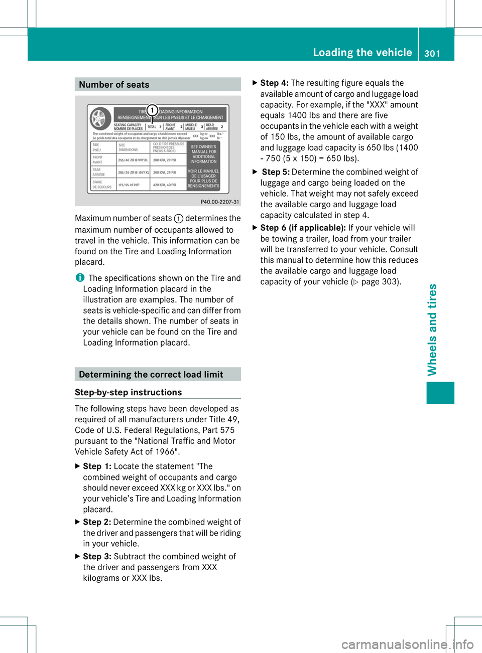
Number of seats
Maximum numbe
rofseats:determines the
maximum number of occupants allowed to
travel in the vehicle. This information can be
found on the Tire and Loading Information
placard.
i The specifications shown on the Tire and
Loading Information placard in the
illustration are examples. The number of
seats is vehicle-specific and can differ from
the details shown. The number of seats in
your vehicle can be found on the Tire and
Loading Information placard. Determining the correct load limit
Step-by-step instructions The following steps have been developed as
required of all manufacturers under Title 49,
Code of U.S.F
ederal Regulations, Part 575
pursuant to the "National Traffic and Motor
Vehicle Safety Act of 1966".
X Step 1: Locate the statement "The
combined weight of occupants and cargo
should never exceed XXX kg or XXX lbs." on
your vehicle’s Tire and Loading Information
placard.
X Step 2: Determine the combined weight of
the driver and passengers that will be riding
in your vehicle.
X Step 3: Subtract the combined weight of
the driver and passengers from XXX
kilograms or XXX lbs. X
Step 4: The resulting figure equals the
available amount of cargo and luggage load
capacity. For example, if the "XXX" amount
equals 1400l bs and there are five
occupants in the vehicle each with a weight
of 150 lbs, the amount of available cargo
and luggage load capacity is 650 lbs (1400
Ò 750 (5 x 150) = 650 lbs).
X Step 5: Determine the combined weight of
luggage and cargo being loaded on the
vehicle. That weight may not safely exceed
the available cargo and luggage load
capacity calculated in step 4.
X Step 6 (if applicable): If your vehicle will
be towing a trailer, load from your trailer
will be transferred to your vehicle. Consult
this manual to determine how this reduces
the available cargo and luggage load
capacity of your vehicle ( Ypage 303). Loading the vehicle
301Wheels and tires Z
Page 314 of 336
Aspect ratio
Relationship between tire height and tire
width in percent. tire pressure
This is pressure inside the tire applying an
outward force to each square inch of the tire's
surface. The tire pressure is specified in
pounds per square inch (psi), in kilopascal
(kPa) or in bar. The tire pressure should only
be corrected when the tires are cold. Tire pressure of cold tires
The tires are cold:
R if the vehicle has been parked without
direct sunligh tonthe tires for at least three
hours and
R if the vehicle has not been driven further
than 1 mile (1.6 km) Tread
The part of the tire that comes into contact
with the road. Bead
The tire bead ensures that the tire sits
securely on the wheel. There are several steel
wires in the bead to prevent the tire from
coming loose from the wheel rim. Sidewall
The part of the tire between the tread and the
bead. Weight of optional extras
The combined weight of those optional extras
that weigh more than the replaced standard
part and more than 2.3 kg (5 lbs). These optional extras, such as high-performance
brakes, level control, a roof rack or a high-
performance battery, are not included in the
curb weight and the weight of the
accessories.
TIN (Tire Identification Number)
This is a unique identifier which can be used
by a tire manufacturer to identify tires, for
example for a product recall, and thus identify
the purchasers. The TIN is made up of the
manufacturer's identity code, tire size, tire
type code and the manufacturing date. Load bearing index
The load bearing index (also load index) is a
code that contains the maximum load bearing
capacity of a tire. Traction
Traction is the result of friction between the
tires and the road surface. Treadwear indicators
Narrow bars (tread wear bars) that are
distributed over the tire tread. If the tire tread
is level with the bars, the wear limit of áin
(1.6 mm) has been reached. Occupant distribution
The distribution of occupants in a vehicle at
their designated seating positions. Total load limit
Nominal load and luggage load plus
68 kilograms (150 lb) multiplied by the
number of seats in the vehicle. Definition of terms for tires and loading
311Wheels and tires Z
Page 325 of 336
Useful information
i This Operator's Manual describes all
models and all standard and optional
equipment of your vehicle available at the
time of publication of the Operator's
Manual. Country-specific differences are
possible. Please note that your vehicle may
not be equipped with all features
described. This also applies to safety-
related systems and functions.
i Please read the information on qualified
specialist workshops (Y page 23).Information regarding technical data
i The data stated here specifically refers to
a vehicle with standard equipment .Consult
an authorized Mercedes-Benz Center for
the data for all vehicle variants and trim
levels. Genuine Mercedes-Benz parts
G
WARNING
Driving safety may be impaired if non-
approved parts, tires and wheels or safety-
relevant accessories are used.
This could lead to malfunctions in safety-
relevant systems, e.g. the brake system. This
could cause you to lose control of your vehicle
and cause an accident.
For this reason, Mercedes-Benz recommends
that you use genuine Mercedes-Benz parts or
parts of equal quality. Only use tires, wheels
and accessories that have been specifically
approved for your vehicle. H
Environmental note
Daimler AG also supplies reconditioned major
assemblies and parts which are of the same
quality as new parts. They are covered by the
same Limited Warranty entitlements as new
parts. !
Air bags and Emergency Tensioning
Devices, as well as control units and
sensors for these restraint systems, may be
installed in the following areas of your
vehicle:
R doors
R door pillars
R door sills
R seats
R dashboard
R instrument cluster
R center console
Do not install accessories such as audio
systems in these areas. Do not carry out
repairs or welding. You could impair the
operating efficiency of the restraint
systems.
Have aftermarket accessories installed at
a qualified specialist workshop. Mercedes-
Benz recommends that you use an
authorized Mercedes-Benz Center for this
purpose.
Genuine Mercedes-Benz parts are subject to
strictq uality control .Each part has been
specially developed, manufactured or
selected for Mercedes-Ben zvehicles and
fine-tuned for them. Only genuine Mercedes-
Benzp arts should therefor ebe used.
More than 300,000 different genuine
Mercedes-Benzp arts are available for
Mercedes-Ben zmodels.
All Mercedes-Benz Centers maintain a supply
of genuine Mercedes-Benz parts for
necessary service and repair work. In
addition, strategically located parts delivery
centers provide quick and reliable parts
service.
Always specify the vehicle identification
number (VIN) (Y page 323) and the engine
number (Y page 324) when ordering genuine
Mercedes-Benz parts. 322
Genuine Mercedes-Benz partsTechnical data