Page 524 of 751

Features of your vehicle
60
4
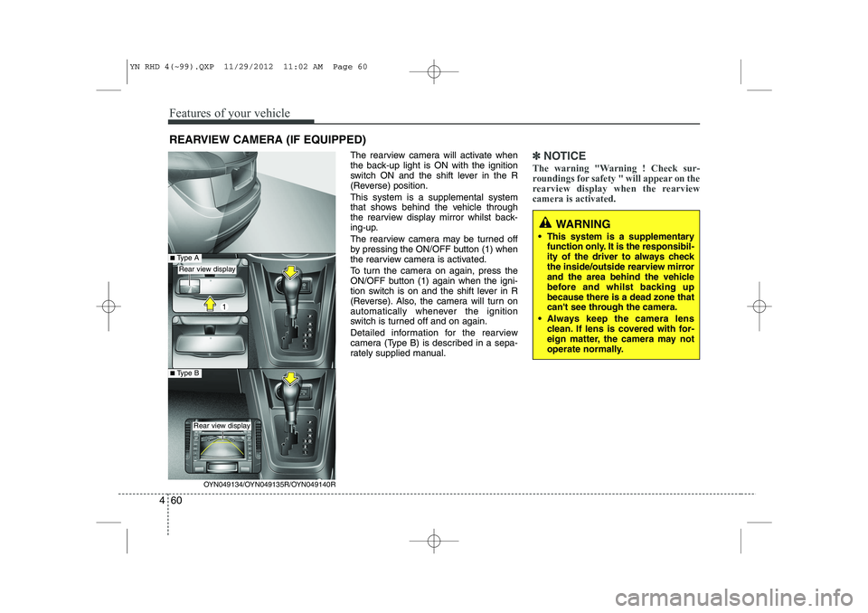
The rearview camera will activate when
the back-up light is ON with the ignition
switch ON and the shift lever in the R
(Reverse) position. This system is a supplemental system
that shows behind the vehicle through
the rearview display mirror whilst back-
ing-up.
The rearview camera may be turned off
by pressing the ON/OFF button (1) when
the rearview camera is activated.
To turn the camera on again, press the
ON/OFF button (1) again when the igni-
tion switch is on and the shift lever in R
(Reverse). Also, the camera will turn on
automatically whenever the ignition
switch is turned off and on again.
Detailed information for the rearview
camera (Type B) is described in a sepa-
rately supplied manual.✽✽
NOTICE
The warning "Warning ! Check sur-
roundings for safety " will appear on the
rearview display when the rearviewcamera is activated.
WARNING
This system is a supplementary function only. It is the responsibil-
ity of the driver to always check
the inside/outside rearview mirror
and the area behind the vehicle
before and whilst backing upbecause there is a dead zone that
can't see through the camera.
Always keep the camera lens clean. If lens is covered with for-
eign matter, the camera may not
operate normally.
REARVIEW CAMERA (IF EQUIPPED)
OYN049134/OYN049135R/OYN049140R
Rear view display
Rear view display
■Type A
■Type B
YN RHD 4(~99).QXP 11/29/2012 11:02 AM Page 60
Page 545 of 751
481
Features of your vehicle
AUTOMATIC CLIMATE CONTROL SYSTEM (IF EQUIPPED)
OYN049062
1. AUTO (automatic control) button
2. A/C display
3. OFF button
4. Air conditioning button
5. Front windscreen defrost button
6. Rear window defroster button
7. Air intake control button
8. Mode selection button
9. Temperature control knob
10. Fan speed control knob
YN RHD 4(~99).QXP 11/29/2012 11:05 AM Page 81
Page 546 of 751
Features of your vehicle
82
4
Automatic heating and air condi- tioning
1. Push the AUTO button. It is indicated
by AUTO on the display. The modes,
fan speeds, air intake and air-condi-tioning will be controlled automatically
by temperature setting. 2. Turn the temperature control knob to
set the desired temperature.
✽✽ NOTICE
Page 549 of 751

485
Features of your vehicle
Temperature conversion
If the battery has been discharged or dis-
connected, the temperature mode dis-
play will reset to Centigrade.
This is normal condition. You can switch the
temperature mode between Centigrade to
Fahrenheit as follows;
Whilst depressing the AUTO button,
depress the OFF button for 3 seconds or
more. The display will change from
Centigrade to Fahrenheit, or from
Fahrenheit to Centigrade.
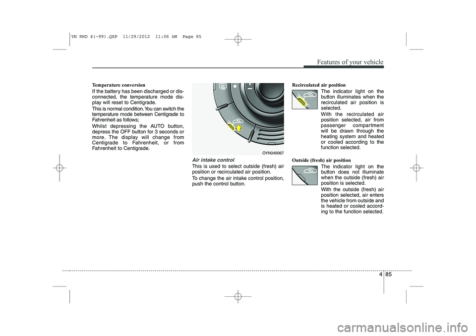
Air intake control
This is used to select outside (fresh) air position or recirculated air position.
To change the air intake control position,
push the control button.Recirculated air position
The indicator light on the
button illuminates when therecirculated air position isselected.
With the recirculated air position selected, air from
passenger compartment
will be drawn through theheating system and heatedor cooled according to thefunction selected.
Outside (fresh) air position The indicator light on the
button does not illuminatewhen the outside (fresh) airposition is selected. With the outside (fresh) air position selected, air enters
the vehicle from outside andis heated or cooled accord-ing to the function selected.
OYN049067
YN RHD 4(~99).QXP 11/29/2012 11:06 AM Page 85
Page 557 of 751

493
Features of your vehicle
INTERIOR FEATURES
LCD monitor (clock, outside tem-
perature, etc.) (if equipped)
The monitor will display the outside tem-
perature, date* and time.
If your vehicle enters into the icy road at
outside temperature range of -5°C to 3°C
(23°F to 37°F), the temperature digits will
blink five times and the symbol ( ) will
illuminate. The date display when the radio power is
turned off.
To change the date*, time, distance unit (km
↔ mi)* or temperature unit(°C ↔
°F), press the SET button for more than1 second.
Then you will enter the set-up mode and
mode changes in the following order as
you press the SET button less than 1second. YEAR* →MONTH* →DAY* →HOUR →
MINUTE →DISTANCE UNIT CHANGE*
→ TEMPERATURE UNIT CHANGE →
Escape set-up mode
Press the SET button less than 1 second to select the mode and set the data usingthe UP( ▲) and DOWN( ▼) button whilst
the selected setting mode blinks.
To cancel the SET UP mode, do one of
the following :
- Press the SET button less than 1 sec- ond in set-up temperature unit change mode
- Press the SET button more than 1 sec- ond in any set-up mode
- After 15 seconds without any key press
- Ignition is ON or OFF in set-up mode
- Battery is disconnected * if equipped Cigarette lighter (if equipped)
For the cigarette lighter to work, the igni-
tion switch must be in the ACC or ONposition.
To use the cigarette lighter, push it all the
way into its socket. When the element isheated, the lighter will pop out to the
“ready” position.
OYN049080R
OYN049106
OYN049132
■
Type A
■Type B
YN RHD 4(~99).QXP 11/29/2012 11:07 AM Page 93
Page 602 of 751
539
Driving your vehicle
You can set the speed limit when you
don’t want to drive over a specific speed.
If you drive over the preset speed limit,
the warning system operates (set speed
limit will blink and chime will sound) until
the vehicle speed returns within thespeed limit.
✽✽NOTICE
Whilst speed limit control in operation,
the cruise control system cannot be acti-vated.
(1) Seed limit ON-OFF button
(2) Cancel button
(3) Resume button
(4) Set button
To set speed limit :
1. Push the speed limit ON-OFF button on the steering wheel, to turn the sys-
tem on. The speed limit indicator light
in the instrument cluster will illuminate. 2. Push the SET- switch.
3. Push the RES+ or SET- switch, and
release it at the desired speed.
Push the RES+ or SET- switch and
hold it. The speed will increase or
decrease by 5 km/h.
The set speed limit will display on the instrument cluster.
SPEED LIMIT CONTROL SYSTEM (IF EQUIPPED)
OYN059016OYN059015
YN RHD 5.QXP 3/31/2012 4:08 PM Page 39
Page 639 of 751
What to do in an emergency
16
6
0. Speed restriction label
1. Sealant bottle and label with
speed restriction
2. Filling hose from sealant bottle to wheel 3. Connectors and cable for the
power outlet direct connection
4. Holder for the sealant bottle
5. Compressor
6. On/off switch 7. Pressure gauge for displaying the
tyre inflation pressure
8. Button for reducing tyre inflation pressure
9. Hose to connect compressor and sealant bottle or compressor and wheel
Connectors, cable and connectionhose are stored in the compressorhousing.
WARNING
Before using the Tyre Mobility Kit,
follow the instructions on the
sealant bottle.
Remove the label with the speed
restriction from the sealant bottle
and apply it to the steering wheel.
Please note the expiry date on the
sealant bottle.
Components of the Tyre Mobility Kit
OAM060015L
YN RHD 6.QXP 3/31/2012 4:10 PM Page 16
Page 701 of 751

749
Maintenance
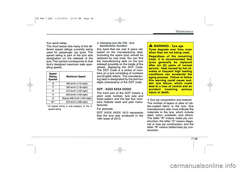
Tyre speed ratings
The chart below lists many of the dif-
ferent speed ratings currently being
used for passenger car tyres. The
speed rating is part of the tyre size
designation on the sidewall of the
tyre. This symbol corresponds to that
tyre's designed maximum safe oper-ating speed.3. Checking tyre life (TIN : TyreIdentification Number)
Any tyres that are over 6 years old,
based on the manufacturing date,(including the spare tyre) should be
replaced by new ones. You can find
the manufacturing date on the tyre
sidewall (possibly on the inside of the
wheel), displaying the DOT Code.
The DOT Code is a series of num-
bers on a tyre consisting of numbers
and English letters. The manufactur-
ing date is designated by the last four
digits (characters) of the DOT code.
DOT : XXXX XXXX OOOO
The front part of the DOT means a
plant code number, tyre size and
tread pattern and the last four num-
bers indicate week and year manu-
factured.
For example:
DOT XXXX XXXX 1613 represents
that the tyre was produced in the
16th week of 2013.
4. Tyre ply composition and material
The number of layers or plies of rub-
ber-coated fabric in the tyre. Tyre
manufacturers also must indicate the
materials in the tyre, which include
steel, nylon, polyester, and others.
The letter "R" means radial ply con-
struction; the letter "D" means diago-
nal or bias ply construction; and theletter "B" means belted-bias ply con-
struction.
S 180 km/h (112 mph)
T 190 km/h (118 mph)
H 210 km/h (130 mph) V 240 km/h (149 mph)
Z Above 240 km/h (149 mph)
W*270 km/h (168 mph)
Maximum Speed
Speed
Rating
Symbol
WARNING - Tyre age
Tyres degrade over time, even
when they are not being used.
Regardless of the remaining
tread, it is recommended that
tyres generally be replaced
after six (6) years of normal
service. Heat caused by hot cli-mates or frequent high loadingconditions can accelerate the
aging process. Failure to followthis warning could cause sud-
den tyre failure, which could
lead to a loss of control and an
accident involving serious
injury or death.
* W speed rating is sub-category of the Z speed rating.
YN RHD 7.QXP 1/15/2013 12:55 PM Page 49