2013 KIA VENGA tow
[x] Cancel search: towPage 140 of 751

Features of your vehicle
68
4
Windshield washers (front)
In the O (OFF) position, pull the lever
gently toward you to spray washer fluid
on the windshield and to run the wipers
1-3 cycles. Use this function when the windshield is
dirty.
The spray and wiper operation will con-
tinue until you release the lever.
If the washer does not work, check the
washer fluid level. If the fluid level, you
will need to add appropriate non-abra-
sive windshield washer fluid to the wash-
er reservoir.
The reservoir filler neck is located in the
front of the engine compartment on the
passenger side.
Auto control (if equipped)
The rain sensor located on the upper end of the windshield glass senses the
amount of rainfall and controls the wiping
cycle for the proper interval. The more it
rains, the faster the wiper operates.
When the rain stops, the wiper stops.
To vary the speed setting, turn the speed control knob (1).
OXM049048E
WARNING
Do not use the washer in freezing
temperatures without first warming
the windshield with the defrosters;
the washer solution could freeze on
the windshield and obscure yourvision.
CAUTION
To prevent possible damage to the wipers or windshield, do not
operate the wipers when the windshield is dry.
To prevent damage to the wiper blades, do not use gasoline,
kerosene, paint thinner, or othersolvents on or near them.
To prevent damage to the wiper arms and other components, donot attempt to move the wipers
manually.
CAUTION
To prevent possible damage to the
washer pump, do not operate the
washer when the fluid reservoir isempty.
OYF049103
Rain sensor
OTFR040207
Rain sensor
YN ENG 4(~99).QXP 4/16/2012 10:19 AM Page 68
Page 146 of 751
Features of your vehicle
74
4
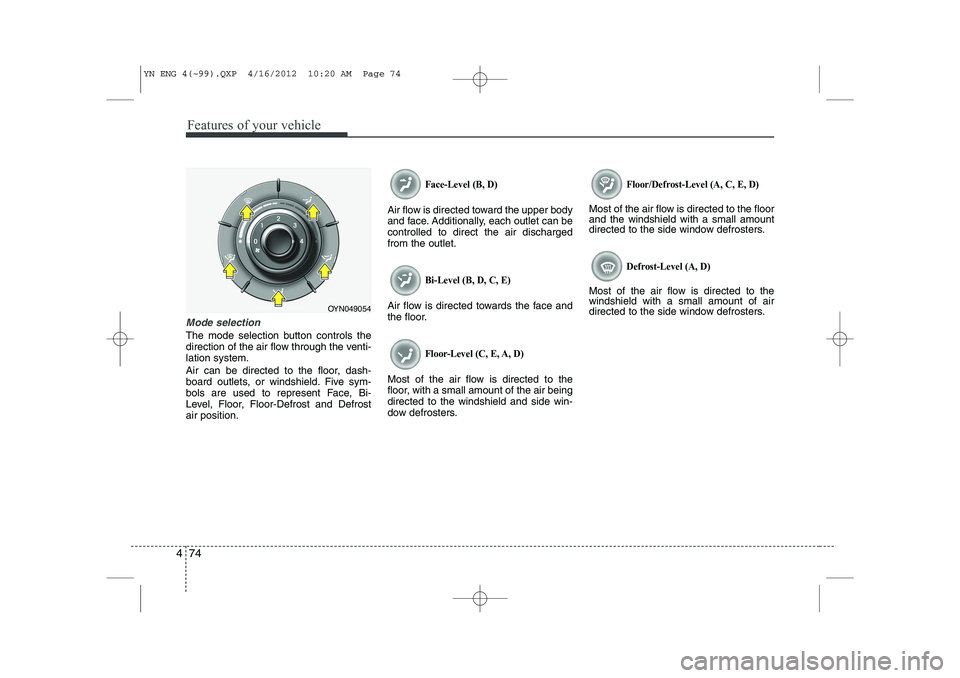
Mode selection
The mode selection button controls the
direction of the air flow through the venti-lation system.
Air can be directed to the floor, dash-
board outlets, or windshield. Five sym-
bols are used to represent Face, Bi-
Level, Floor, Floor-Defrost and Defrostair position.
Face-Level (B, D)
Air flow is directed toward the upper body
and face. Additionally, each outlet can becontrolled to direct the air dischargedfrom the outlet.
Bi-Level (B, D, C, E)
Air flow is directed towards the face and
the floor.
Floor-Level (C, E, A, D)
Most of the air flow is directed to the
floor, with a small amount of the air beingdirected to the windshield and side win-
dow defrosters.
Floor/Defrost-Level (A, C, E, D)
Most of the air flow is directed to the floor and the windshield with a small amount
directed to the side window defrosters.
Defrost-Level (A, D)
Most of the air flow is directed to thewindshield with a small amount of air
directed to the side window defrosters.
OYN049054
YN ENG 4(~99).QXP 4/16/2012 10:20 AM Page 74
Page 155 of 751
483
Features of your vehicle
Manual heating and air condition- ing The heating and cooling system can be
controlled manually by pushing buttons
other than the AUTO button. In this case,
the system works sequentially according
to the order of buttons selected.
When pressing any button (or turning
any knob) except AUTO button while
automatic operation, the functions not
selected will be controlled automatically.
1. Start the engine.
2. Set the mode to the desired position.
3. Set the temperature control to thedesired position.
4. Set the air intake control to the outside (fresh) air position.
5. Set the fan speed control to the desired speed.
6. If air conditioning is desired, turn the air conditioning system on.
Press the AUTO button in order to con-
vert to full automatic control of the sys-tem.
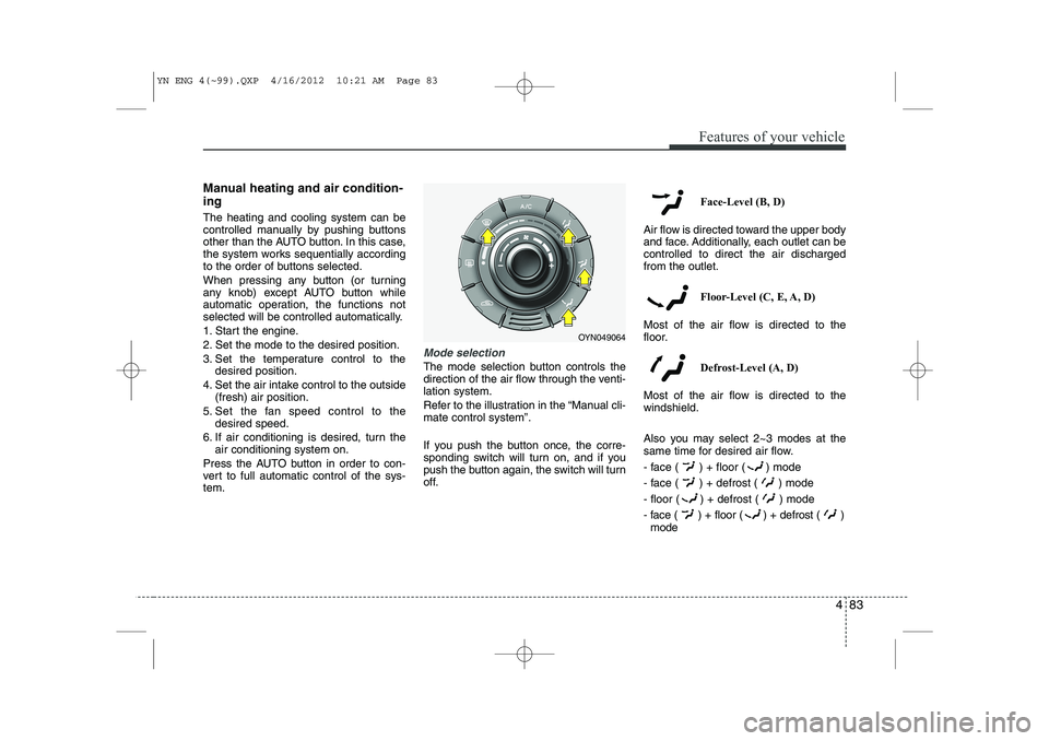
Mode selection
The mode selection button controls the
direction of the air flow through the venti-lation system.
Refer to the illustration in the “Manual cli- mate control system”.
If you push the button once, the corre-
sponding switch will turn on, and if you
push the button again, the switch will turn
off. Face-Level (B, D)
Air flow is directed toward the upper body
and face. Additionally, each outlet can becontrolled to direct the air dischargedfrom the outlet.
Floor-Level (C, E, A, D)
Most of the air flow is directed to the
floor.
Defrost-Level (A, D)
Most of the air flow is directed to thewindshield.
Also you may select 2~3 modes at the
same time for desired air flow.
- face ( ) + floor ( ) mode
- face ( ) + defrost ( ) mode
- floor ( ) + defrost ( ) mode
- face ( ) + floor ( ) + defrost ( ) mode
OYN049064
YN ENG 4(~99).QXP 4/16/2012 10:21 AM Page 83
Page 173 of 751
4 101
Features of your vehicle
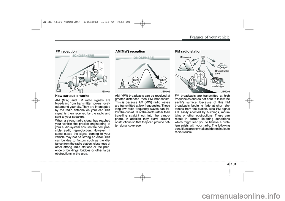
How car audio works
AM (MW) and FM radio signals are
broadcast from transmitter towers locat-
ed around your city. They are intercepted
by the radio antenna on your car. This
signal is then received by the radio and
sent to your speakers.
When a strong radio signal has reached
your vehicle the precise engineering of
your audio system ensures the best pos-
sible audio reproduction. However in
some cases the signal coming to your
vehicle may not be strong an clear. This
can be due to factors such as the dis-
tance from the radio station, closeness of
other strong radio stations or the pres-
ence of buildings, bridges or other large
obstructions in the area.AM (MW) broadcasts can be received at
greater distances then FM broadcasts.
This is because AM (MW) radio waves
are transmitted at low frequencies. These
long low radio frequency waves can fol-
low the curvature of the earth rather then
travelling straight out into the atmos-
phere. In addition they curve around
obstructions so that they can provide bet-
ter signal coverage.
FM broadcasts are transmitted at high
frequencies and do not bent to follow the
earth’s surface. Because of this FM
broadcasts begin to fade at short dis-
tances from the station. Also FM signal
are easily affected by buildings, moun-
tains or other obstructions. These can
result in certain listening conditions
which might lead you to believe a prob-
lem exists with your radio. The following
conditions are normal and do not indicate
radio trouble.
JBM002
AM(MW) receptionJBM003
FM radio station
Mountains
Unobstructed area
Iron bridges
Buildings
JBM001
FM reception
YN ENG 4(100~AUDIO).QXP 4/16/2012 10:13 AM Page 101
Page 205 of 751

5
Before driving / 5-3 Key positions / 5-4Engine start/stop button / 5-8ISG(idle stop and go) system / 5-14Manual transaxle / 5-16Automatic transaxle / 5-19Brake system / 5-24
Cruise control system / 5-35
Speed limit control system / 5-39Economical operation / 5-41Special driving conditions / 5-43
Winter driving / 5-48
Trailer towing / 5-52
Vehicle weight / 5-60
Driving your vehicle
YN ENG 5.QXP 4/16/2012 10:01 AM Page 1
Page 208 of 751
Driving your vehicle
4
5
Illuminated ignition switch (if equipped)
Whenever a front door is opened, the
ignition switch will be illuminated for your
convenience, provided the ignition switch
is not in the ON position. The light will go
off immediately when the ignition switch
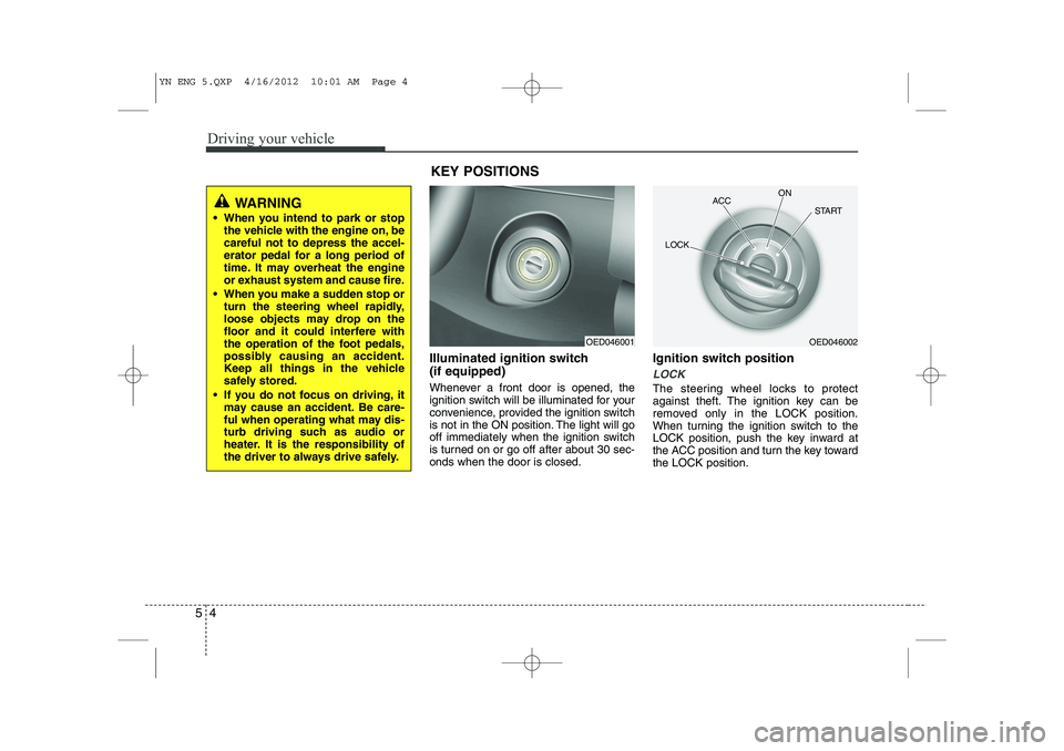
is turned on or go off after about 30 sec-onds when the door is closed. Ignition switch position
LOCK
The steering wheel locks to protect
against theft. The ignition key can be
removed only in the LOCK position.
When turning the ignition switch to the
LOCK position, push the key inward at
the ACC position and turn the key towardthe LOCK position.
OED046001OED046002
ACC
ON
START
LOCK
WARNING
When you intend to park or stop the vehicle with the engine on, be careful not to depress the accel-
erator pedal for a long period of
time. It may overheat the engine
or exhaust system and cause fire.
When you make a sudden stop or turn the steering wheel rapidly,
loose objects may drop on the
floor and it could interfere with
the operation of the foot pedals,
possibly causing an accident.
Keep all things in the vehicle
safely stored.
If you do not focus on driving, it may cause an accident. Be care-
ful when operating what may dis-
turb driving such as audio or
heater. It is the responsibility of
the driver to always drive safely.
KEY POSITIONS
YN ENG 5.QXP 4/16/2012 10:01 AM Page 4
Page 225 of 751
521
Driving your vehicle
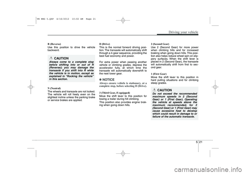
R (Reverse)
Use this position to drive the vehicle
backward. N (Neutral)
The wheels and transaxle are not locked.
The vehicle will roll freely even on the
slightest incline unless the parking brake
or service brakes are applied.D (Drive)
This is the normal forward driving posi-
tion. The transaxle will automatically shift
through a 4-gear sequence, providing the
best fuel economy and power.
For extra power when passing another
vehicle or climbing grades, depress the
accelerator fully, at which time the
transaxle will automatically downshift to
the next lower gear.
✽✽
NOTICE
Always ensure vehicle is stationary, at a
complete stop, before selecting D (Drive).
3 (Third Gear, if equipped)
Move the shift lever to this position for
towing a trailer during hill climbing.
This position also provides engine brak-
ing when going down hills. 2 (Second Gear)
Use 2 (Second Gear) for more power
when climbing hills and for increased
braking when going down hills. This posi-tion also helps reduce wheel spin on slip-
pery surfaces. When the shift lever is
placed in 2 (Second Gear), the transaxlewill automatically shift from first to sec-
ond gear. 1 (First Gear)
Move the shift lever to this position in
hard pulling situations and for climbing
steep grades.
CAUTION
Always come to a complete stop
before shifting into or out of R(Reverse); you may damage thetransaxle if you shift into R whilethe vehicle is in motion, except as
explained in “Rocking the vehicle”in this section.
CAUTION
Do not exceed the recommendedmaximum speeds in 2 (SecondGear) or 1 (First Gear). Operating
the vehicle at speeds above themaximum recommended, for 2 (Second Gear) or 1 (First Gear) maycause excessive heat to develop
which could result in damage to or failure of the automatic transaxle.
YN ENG 5.QXP 4/16/2012 10:02 AM Page 21
Page 248 of 751
Driving your vehicle
44
5
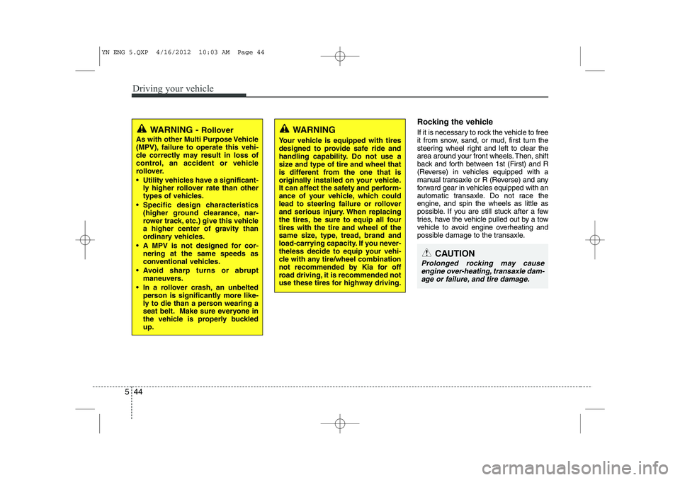
Rocking the vehicle
If it is necessary to rock the vehicle to free
it from snow, sand, or mud, first turn the
steering wheel right and left to clear the
area around your front wheels. Then, shift
back and forth between 1st (First) and R
(Reverse) in vehicles equipped with a
manual transaxle or R (Reverse) and any
forward gear in vehicles equipped with an
automatic transaxle. Do not race the
engine, and spin the wheels as little as
possible. If you are still stuck after a few
tries, have the vehicle pulled out by a tow
vehicle to avoid engine overheating and
possible damage to the transaxle.
CAUTION
Prolonged rocking may cause
engine over-heating, transaxle dam-age or failure, and tire damage.
WARNING
Your vehicle is equipped with tires
designed to provide safe ride and
handling capability. Do not use a
size and type of tire and wheel that
is different from the one that is
originally installed on your vehicle.
It can affect the safety and perform-
ance of your vehicle, which could
lead to steering failure or rollover
and serious injury. When replacing
the tires, be sure to equip all fourtires with the tire and wheel of the
same size, type, tread, brand and
load-carrying capacity. If you never-
theless decide to equip your vehi-
cle with any tire/wheel combination
not recommended by Kia for off
road driving, it is recommended not
use these tires for highway driving.WARNING - Rollover
As with other Multi Purpose Vehicle
(MPV), failure to operate this vehi-
cle correctly may result in loss of
control, an accident or vehicle
rollover.
Utility vehicles have a significant- ly higher rollover rate than other
types of vehicles.
Specific design characteristics (higher ground clearance, nar-
rower track, etc.) give this vehicle
a higher center of gravity than
ordinary vehicles.
A MPV is not designed for cor- nering at the same speeds as
conventional vehicles.
Avoid sharp turns or abrupt maneuvers.
In a rollover crash, an unbelted person is significantly more like-
ly to die than a person wearing a
seat belt. Make sure everyone in
the vehicle is properly buckledup.
YN ENG 5.QXP 4/16/2012 10:03 AM Page 44