Page 433 of 1168

What to do in an emergency
12
6
7. Place the jack at the front or rear
jacking position closest to the tire
you are changing. Place the jackat the designated locations under
the frame. The jacking positions
are plates welded to the frame
with two tabs and a raised dot to
index with the jack. 8. Insert the jack handle into the jack
and turn it clockwise, raising the
vehicle until the tire just clears the
ground. This measurement is
approximately 30 mm (1.2 in).
Before removing the wheel lug
nuts, make sure the vehicle is sta-
ble and that there is no chance for
movement or slippage. 9. Loosen the wheel nuts and
remove them with your fingers.Slide the wheel off the studs and
lay it flat so it cannot roll away. To
put the wheel on the hub, pick up
the spare tire, line up the holeswith the studs and slide the wheel
onto them. If this is difficult, tip thewheel slightly and get the top holein the wheel lined up with the top
stud. Then jiggle the wheel back
and forth until the wheel can be
slid over the other studs.
WARNING - Jack location
To reduce the possibility of
injury, be sure to use only the
jack provided with the vehicle
and in the correct jack position;
never use any other part of the
vehicle for jack support.
OJD062002OJD062005
JD eng 6.QXP 7/17/2012 10:47 AM Page 12
Page 511 of 1168

Maintenance
58
7
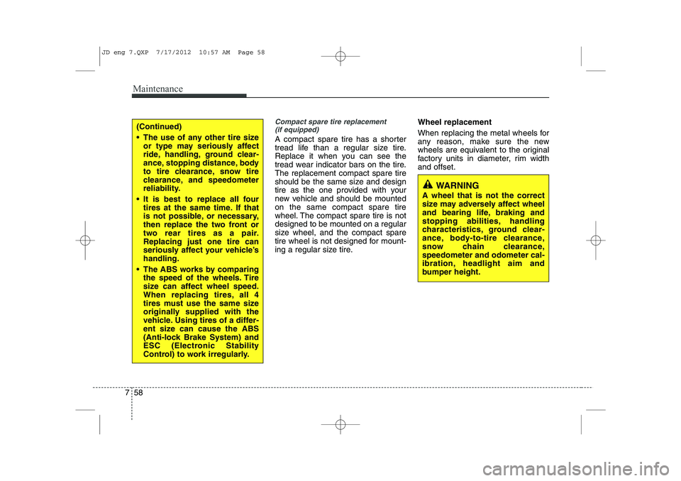
Compact spare tire replacement
(if equipped)
A compact spare tire has a shorter
tread life than a regular size tire.
Replace it when you can see the
tread wear indicator bars on the tire.The replacement compact spare tire
should be the same size and design
tire as the one provided with your
new vehicle and should be mountedon the same compact spare tire
wheel. The compact spare tire is notdesigned to be mounted on a regular
size wheel, and the compact spare
tire wheel is not designed for mount-
ing a regular size tire. Wheel replacement
When replacing the metal wheels for
any reason, make sure the new
wheels are equivalent to the original
factory units in diameter, rim widthand offset.
(Continued)
The use of any other tire size
or type may seriously affect
ride, handling, ground clear-
ance, stopping distance, body
to tire clearance, snow tire
clearance, and speedometer
reliability.
It is best to replace all four tires at the same time. If that
is not possible, or necessary,
then replace the two front or
two rear tires as a pair.Replacing just one tire can
seriously affect your vehicle’shandling.
The ABS works by comparing the speed of the wheels. Tire
size can affect wheel speed.
When replacing tires, all 4
tires must use the same size
originally supplied with the
vehicle. Using tires of a differ-
ent size can cause the ABS
(Anti-lock Brake System) and
ESC (Electronic Stability
Control) to work irregularly.
WARNING
A wheel that is not the correct
size may adversely affect wheel
and bearing life, braking and
stopping abilities, handling
characteristics, ground clear-
ance, body-to-tire clearance,
snow chain clearance,speedometer and odometer cal-
ibration, headlight aim and
bumper height.
JD eng 7.QXP 7/17/2012 10:57 AM Page 58
Page 522 of 1168

769
Maintenance
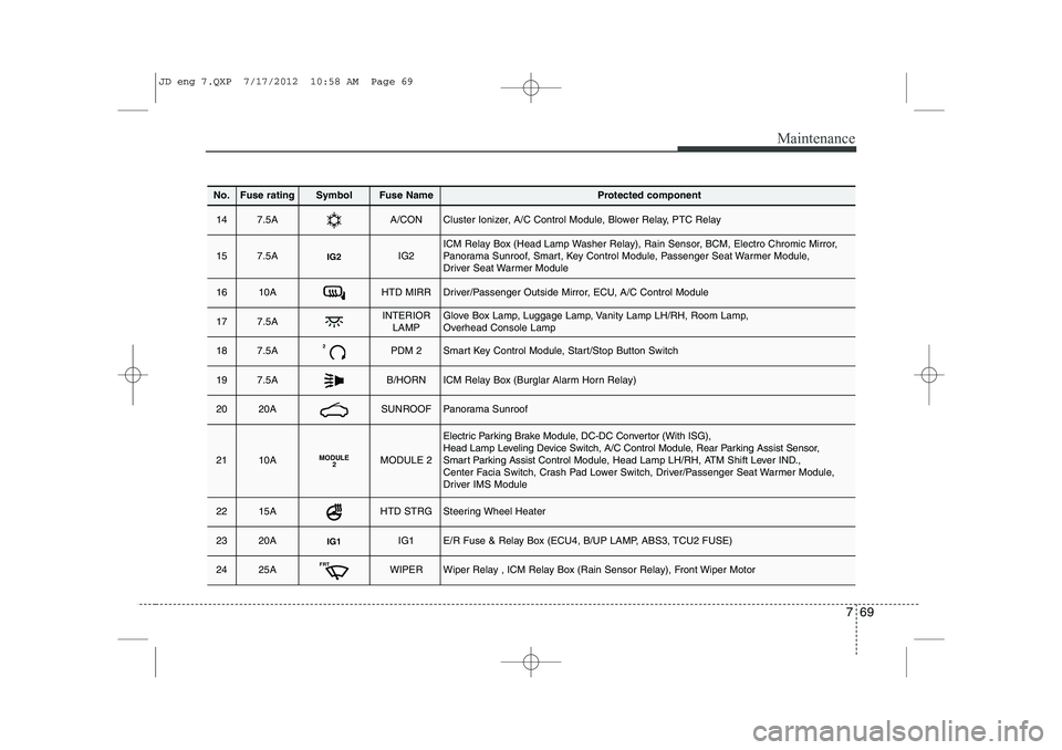
No.Fuse ratingSymbolFuse NameProtected component
147.5AA/CONCluster Ionizer, A/C Control Module, Blower Relay, PTC Relay
157.5AIG2IG2ICM Relay Box (Head Lamp Washer Relay), Rain Sensor, BCM, Electro Chromic Mirror,
Panorama Sunroof, Smart, Key Control Module, Passenger Seat Warmer Module,
Driver Seat Warmer Module
1610AHTD MIRRDriver/Passenger Outside Mirror, ECU, A/C Control Module
177.5AINTERIORLAMPGlove Box Lamp, Luggage Lamp, Vanity Lamp LH/RH, Room Lamp,
Overhead Console Lamp
187.5A2PDM 2Smart Key Control Module, Start/Stop Button Switch
197.5AB/HORNICM Relay Box (Burglar Alarm Horn Relay)
2020ASUNROOFPanorama Sunroof
2110AMODULE 2MODULE 2
Electric Parking Brake Module, DC-DC Convertor (With ISG),
Head Lamp Leveling Device Switch, A/C Control Module, Rear Parking Assist Sensor,
Smart Parking Assist Control Module, Head Lamp LH/RH, ATM Shift Lever IND.,
Center Facia Switch, Crash Pad Lower Switch, Driver/Passenger Seat Warmer Module,
Driver IMS Module
2215AHTD STRGSteering Wheel Heater
2320AIG1IG1E/R Fuse & Relay Box (ECU4, B/UP LAMP, ABS3, TCU2 FUSE)
2425AFRTWIPERWiper Relay , ICM Relay Box (Rain Sensor Relay), Front Wiper Motor
JD eng 7.QXP 7/17/2012 10:58 AM Page 69
Page 527 of 1168

Maintenance
74
7
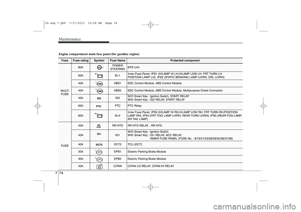
Fuse Fuse ratingSymbolFuse NameProtected component
MULTI
FUSE
80A1POWER
STEERINGEPS Unit
60AB+1B+1Inner Fuse Panel, IPS1 (H/LAMP HI LH,H/LAMP LOW LH, FRT TURN LH,
POSITION LAMP LH), IPS2 (STATIC BENDING LAMP LH/RH, DRL LH/RH)
40A1ABS1ESC Control Module, ABS Control Module
40A2ABS2ESC Control Module, ABS Control Module, Multipurpose Check Connector
40AIG2IG2W/O Smart Key : Ignition Switch, START RELAY
With Smart Key : IG2 RELAY, START RELAY
60APTCPTCPTC Relay
60AB+2B+2Inner Fuse Panel, IPS3 (H/LAMP HI RH,H/LAMP LOW RH, FRT TURN RH,POSITION
LAMP RH), IPS4 (FRT FOG LAMP LH/RH, REAR TURN LH/RH), IPS5 (REAR FOG LAMP,
INT TAIL LAMP)
FUSE
40ARR
HTDRR HTDRR HTD RELAY , RR HTD
40AIG1IG1W/O Smart Key : Ignition Switch
With Smart Key : IG1 RELAY, ACC RELAY,
INNER FUSE PANEL (FUSE No. - 8/13/21/23/28/29/35/36/37/38)
40ADCT2DCT2TCU (DCT)
30A1EPB1Electric Parking Brake Module
30A2EPB2Electric Parking Brake Module
40AC/FANC/FAN LO RELAY, C/FAN HI RELAY
Engine compartment main fuse panel (for gasoline engine)
JD eng 7.QXP 7/17/2012 10:58 AM Page 74
Page 528 of 1168
775
Maintenance
FuseFuse ratingSymbolFuse NameProtected component
FUSE
15ADEICERICM Relay Box (Front Deicer Relay)
15ASTOP
LAMPSTOP LAMPStop Signal Electronic Relay , HAC RELAY
20A5TCU1TCU
40ADCT1DCT1TCU (DCT)
40A7EMSEMS Box (FUSE No. - 1/2/3/4/5/6/7/8/9)
50AB+3B+3Inner Fuse Panel (Leak Current Autocut Device, Fuse No. - 6/19/20/17/32/26/25)
50ABLOWERBLOWER RELAY
10A A/CONA/C Control Module
10AWIPER FRTECU, Rain Sensor
10AB/UP
LAMPB/UP LPM/T : Back-up Lamp Switch, A/T : Transaxle Range Switch, TCU
15A4ECU4Smart Key Control Module, Immobilizer Module, ECU
10A3ABS3ESC Control Module, ABS Control Module, Yaw Rate Sensor, HAC, ESS RELAY
15A6TCU2Transaxle Range Switch, TCU, Stop Lamp Switch
JD eng 7.QXP 7/17/2012 10:58 AM Page 75
Page 530 of 1168

777
Maintenance
FuseFuse ratingSymbolFuse NameProtected component
MULTIFUSE
80A1POWER
STEERINGEPS Unit
60AB+1B+1Inner Fuse Panel, IPS1 (H/LAMP HI LH,H/LAMP LOW LH, FRT TURN LH, POSITION LAMP LH),
IPS2 (STATIC BENDING LAMP LH/RH, DRL LH/RH)
40A1ABS1ESC Control Module, ABS Control Module
40A2ABS2ESC Control Module, ABS Control Module, Multipurpose Check Connector
40AIG2IG2W/O Smart Key : Ignition Switch, START RELAYWith Smart Key : IG2 RELAY, START RELAY, INNER FUSE PANEL (Fuse No. - 14/24/22/15/10)
60AB+2B+2Inner Fuse Panel, IPS3 (H/LAMP HI RH,H/LAMP LOW RH, FRT TURN RH,
POSITION LAMP RH), IPS4 (FRT FOG LAMP LH/RH, REAR TURN LH/RH),
IPS5 (REAR FOG LAMP, INT TAIL LAMP)
FUSE
40ARR
HTDRR HTDRR HTD RELAY , RR HTD
40AIG1IG1W/O Smart Key : Ignition Switch
With Smart Key : IG1 RELAY, ACC RELAY, INNER FUSE PANEL ( Fuse No. - 38/36/21/37/
23/29/28, Fuse No. - 13/8/35)
30A1EPB1Electric Parking Brake Module
30A2EPB2Electric Parking Brake Module
50AC/FANC/FAN LO RELAY, C/FAN HI RELAY
15ADEICERICM Relay Box (Front Deicer Relay)
15ASTOP
LAMPSTOP LAMPStop Signal Electronic Relay, HAC RELAY
Engine compartment main fuse panel (for diesel engine)
JD eng 7.QXP 7/17/2012 10:58 AM Page 77
Page 531 of 1168
Maintenance
78
7
FuseFuse ratingSymbolFuse NameProtected component
FUSE
20A5TCU1TCU
40AFUEL
HEATERFUEL HEATER RELAY
40A7EMSEMS BOX (Fuse No. - 1/2/3/4/5/6/7/8/9)
50AB+3B+3Inner Fuse Panel (Leak Current Autocut Device, Fuse No. - 6/19/20/17/32/26/25)
50ABLOWERBLOWER RELAY
10AA/CONA/C Control Module
10AWIPER FRTECU, Rain Sensor
10AB/UP
LAMPB/UP LPM/T : Back-up Lamp Switch, A/T : Transaxle Range Switch, TCU
15A4ECU4Smart Key Control Module, Immobilizer Module, ECU, Air Flow Sensor,
Fuel Water Sensor
10A3ABS3ESC Control Module, ABS Control Module, Yaw Rate Sensor, HAC, ESS RELAY
15A6TCU2Transaxle Range Switch, TCU
JD eng 7.QXP 7/17/2012 10:58 AM Page 78
Page 537 of 1168

Maintenance
84
7
13. Connect the headlight bulb socket
connector.
14. Install the headlight bulb cover by turning it clockwise.
15. Connect the power connector to the back of the headlight assembly.Position light (3, bulb type)
Follow the steps 1 to 9 from the previous
page.
10. Pull out the socket from the assembly.
11. Pull the bulb out of the socket.
12. Insert a new bulb into the socket.
13. Install the socket into the assembly.
14. Install the headlight bulb cover byturning it clockwise.
Headlight (Low, Non-HID Type)
Follow the steps 1 to 7 from the previous
page.
8. Remove the cover by turning it coun-terclockwise.
9. Remove the socket from the assembly by turning the socket counterclockwise
until the tabs on the socket align with
the slots on the assembly.
10. Pull the bulb out of the socket.
11. Insert a new bulb into the socket.
12. Install the socket in the assembly by aligning the tabs on the socket with
the slots in the assembly. Push the
socket into the assembly and turn the
socket clockwise.
13. Install the headlight bulb cover by turning it clockwise.
OJD072042
JD eng 7.QXP 7/17/2012 10:59 AM Page 84