Page 123 of 1168

Features of your vehicle
44
4
Remote control
The electric remote control mirror switch
allows you to adjust the position of the
left and right outside rearview mirrors. To
adjust the position of either mirror, move
the lever (1) to R (Right) or L (Left) to
select the right side mirror or the left side
mirror, then press a corresponding pointon the mirror adjustment control to posi-
tion the selected mirror up, down, left or
right.
After adjustment, put the lever into neu-
tral (center) position to prevent inadver-tent adjustment.
Folding the outside rearview mirror
Manual type
To fold outside rearview mirror, grasp the
housing of mirror and then fold it toward
the rear of the vehicle.
CAUTION
The mirrors stop moving when
they reach the maximum adjust-
ing angles, but the motor contin-ues to operate while the switch ispressed. Do not press the switchlonger than necessary, the motor
may be damaged.
Do not attempt to adjust the out- side rearview mirror by hand.Doing so may damage the parts.
OJD042033OJD042034
JD eng 4a(~168).qxp 7/17/2012 10:18 AM Page 44
Page 133 of 1168

Features of your vehicle
54
4
Elapsed time
This mode indicates the total time trav-
eled since the last driving time reset.
Even if the vehicle is not in motion, the
driving time keeps going while the engine
is running.
The meter’s working range is from 0:00~99:59.
Pressing the button for more than 1
second, when the driving time is being
displayed, clears the driving time to zero(0:00).
Engine coolant temperature gauge
This gauge shows the temperature of the
engine coolant when the ignition switchis ON.
Do not continue driving with an overheat-
ed engine. If your vehicle overheats, refer
to “If the engine overheats” in section 6.
CAUTION
If the gauge pointer moves beyond
the normal range area toward the
“130°C”, it indicates overheatingthat may damage the engine.
WARNING
Never remove the radiator cap
when the engine is hot. The enginecoolant is under pressure and
could cause severe burns. Wait
until the engine is cool before
adding coolant to the reservoir.
OJD042057OJD042058
JD eng 4a(~168).qxp 7/17/2012 10:18 AM Page 54
Page 146 of 1168
467
Features of your vehicle
Engine coolant temperature gauge
This gauge shows the temperature of the
engine coolant when the ignition switchis ON.
Do not continue driving with an overheat-
ed engine. If your vehicle overheats, refer
to “If the engine overheats” in section 6.
Lane Departure Warning System(LDWS) Mode (if equipped)
This mode displays the state of the Lane
Departure Warning System (LDWS).
For more details, refer to “Lane departure
warning system” in section 5.
CAUTION
If the gauge pointer moves beyondthe normal range area toward the
“130°C” position, it indicates over-heating that may damage the engine.
WARNING
Never remove the radiator cap
when the engine is hot. The enginecoolant is under pressure and
could cause severe burns. Wait
until the engine is cool before
adding coolant to the reservoir.
OJD042176OJD042180
JD eng 4a(~168).qxp 7/17/2012 10:19 AM Page 67
Page 171 of 1168

Features of your vehicle
92
4
Non-operational conditions of rear parking assist system
The rear parking assist system may
not operate properly when:
1. Moisture is frozen to the sensor. (It will
operate normally when the moisture has been cleared.)
2. The sensor is covered with foreign matter, such as snow or water, or the
sensor cover is blocked. (It will operate
normally when the material is removed
or the sensor is no longer blocked.)
3. Driving on uneven road surfaces (unpaved roads, gravel, bumps, gradi-ent).
4. Objects generating excessive noise (vehicle horns, loud motorcycle
engines, or truck air brakes) are within
range of the sensor.
5. Heavy rain or water spray exists.
6. Wireless transmitters or mobile phones are within range of the sensor.
7. Trailer towing. The detecting range may decrease when:
1. The sensor is stained with foreign mat-
ter such as snow or water. (The sens-
ing range will return to normal when
removed.)
2. Outside air temperature is extremely hot or cold.
The following objects may not be rec-
ognized by the sensor:
1. Sharp or slim objects such as ropes, chains or small poles.
2. Objects which tend to absorb the sen- sor frequency such as clothes, spongy
material or snow.
3. Undetectable objects smaller than 1 m (40 in.) and narrower than 14 cm (6 in.)
in diameter. Rear parking assist system pre- cautions
The rear parking assist system may
not sound sequentially depending on the speed and shapes of the objectsdetected.
The rear parking assist system may malfunction if the vehicle bumperheight or sensor installation has been
modified or damaged. Any non-factory
installed equipment or accessories
may also interfere with the sensor per-
formance.
The sensor may not recognize objects less than 30 cm (11.8 in.) from the sen-
sor, or it may sense an incorrect dis-
tance. Use caution.
When the sensor is frozen or stained with snow, dirt, or water, the sensor
may be inoperative until the stains are
removed using a soft cloth.
Do not push, scratch or strike the sen- sor. Sensor damage could occur.
JD eng 4a(~168).qxp 7/17/2012 10:21 AM Page 92
Page 192 of 1168
4 113
Features of your vehicle
High - beam operation
1. Turn the light switch to the headlightposition.
2. Push the lever away from you. The high-beam indicator will light when
the headlight high beams are switched on.
To prevent the battery from being dis- charged, do not leave the lights on fora prolonged time while the engine is
not running.Flashing headlights
Pull the lever towards you. It will return to
the normal position when released. The
headlight switch does not need to be on
to use this flashing feature.
WARNING
Do not use high beam when there
are other vehicles. Using highbeam could obstruct the other dri-ver's vision.
OED040801OED040802
JD eng 4a(~168).qxp 7/17/2012 10:23 AM Page 113
Page 199 of 1168

Features of your vehicle
120
4
Windshield washers (front)
In the O (Off) position, pull the lever gen-
tly toward you to spray washer fluid on
the windshield and to run the wipers 1-3
cycles. Use this function when the windshield is
dirty.
The spray and wiper operation will con-
tinue until you release the lever.
If the washer does not work, check the
washer fluid level. If the fluid level is not
sufficient, you will need to add appropri-
ate non-abrasive windshield washer fluid
to the washer reservoir.
The reservoir filler neck is located in the
front of the engine compartment on the
passenger side.
OXM049048E
WARNING
Do not use the washer in freezing
temperatures without first warming
the windshield with the defrosters;
the washer solution could freeze on
the windshield and obscure yourvision.
CAUTION
To prevent possible damage to the wipers or windshield, do notoperate the wipers when the
windshield is dry.
To prevent damage to the wiper blades, do not use gasoline,
kerosene, paint thinner, or othersolvents on or near them.
To prevent damage to the wiper arms and other components, do
not attempt to move the wipersmanually.
CAUTION
To prevent possible damage to the
washer pump, do not operate the
washer when the fluid reservoir isempty.
JD eng 4a(~168).qxp 7/17/2012 10:23 AM Page 120
Page 208 of 1168

4 129
Features of your vehicle
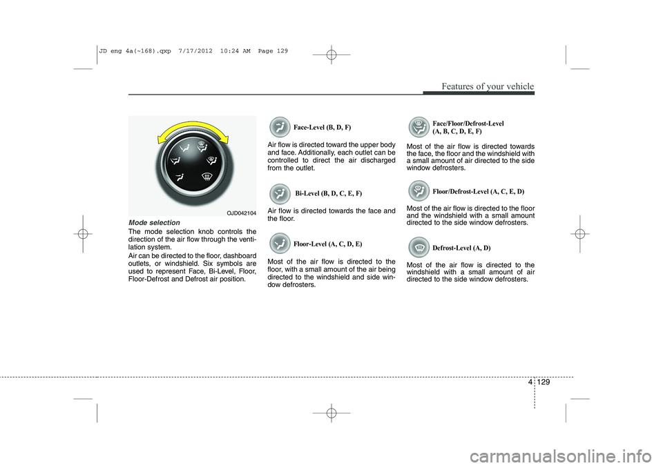
Mode selection
The mode selection knob controls the
direction of the air flow through the venti-lation system.
Air can be directed to the floor, dashboard
outlets, or windshield. Six symbols are
used to represent Face, Bi-Level, Floor,Floor-Defrost and Defrost air position.
Face-Level (B, D, F)
Air flow is directed toward the upper body
and face. Additionally, each outlet can becontrolled to direct the air dischargedfrom the outlet.
Bi-Level (B, D, C, E, F)
Air flow is directed towards the face and
the floor.
Floor-Level (A, C, D, E)
Most of the air flow is directed to the
floor, with a small amount of the air beingdirected to the windshield and side win-
dow defrosters.
Face/Floor/Defrost-Level (A, B, C, D, E, F)
Most of the air flow is directed towards
the face, the floor and the windshield witha small amount of air directed to the side
window defrosters.
Floor/Defrost-Level (A, C, E, D)
Most of the air flow is directed to the floorand the windshield with a small amount
directed to the side window defrosters.
Defrost-Level (A, D)
Most of the air flow is directed to thewindshield with a small amount of air
directed to the side window defrosters.
OJD042104
JD eng 4a(~168).qxp 7/17/2012 10:24 AM Page 129
Page 219 of 1168
Features of your vehicle
140
4
Face-Level (B, D, F*)
Air flow is directed toward the upper body
and face. Additionally, each outlet can becontrolled to direct the air dischargedfrom the outlet.
Floor-Level (A, C, D, E)
Most of the air flow is directed to the
floor. Defrost-Level (A, D)
Most of the air flow is directed to thewindshield.
Also you may select 2~3 modes at the
same time.
- face ( ) + floor ( ) mode
- face ( ) + defrost ( ) mode
- floor ( ) + defrost ( ) mode
- face ( ) + floor ( ) + defrost ( ) mode
* : if equipped Maximum (MAX) defrost mode
When you select the MAX defrost mode,
the following system will set automatically:
The air conditioning system will be turn
on.
The outside(fresh) air position will be selected.
The fan speed will set to the high speed.
To turn the MAX defrost mode off, press
the mode button or MAX defrost button
again or AUTO button.
OJD042116OJD042122
JD eng 4a(~168).qxp 7/17/2012 10:25 AM Page 140