2013 JEEP GRAND CHEROKEE air conditioning
[x] Cancel search: air conditioningPage 95 of 408

PrimaryAlternate (s)
send
set up phone settings or
phone set up
transfer call
Uconnect® Tutorial
voice training
work
yes
VOICE COMMAND — IF
EQUIPPED
Voice Command System Operation
The Uconnect® Voice Command sys-
tem allows you to control your AM,
FM radio, disc player, USB Mass
Storage Class device, iPod® family of
devices, Bluetooth® Streaming Audio
device, and a memo recorder.
NOTE:
Take care to speak into the Voice Interface
System as calmly and normally as possible.
The ability of the Voice Interface System to
recognize user voice commands may be
negatively affected by rapid speaking or a
raised voice level.
WARNING!
Any voice commanded system should be
used only in safe driving conditions following
all applicable laws. Your attention should be
focused on safely operating the vehicle. Fail-
ure to do so may result in a collision causing
serious injury or death.
When you press the Voice Command
but-
ton, you will hear a beep. The beep is your
signal to give a command.
NOTE:
If you do not say a command within a few
seconds, the system will present you with a
list of options. If you ever wish to interrupt the system while it
lists options, press the Voice Command
button, listen for the beep, and say your
command.
Pressing the Voice Command
button while
the system is speaking is known as “barging in.”
The system will be interrupted, and after the
beep, you can add or change commands. This
will become helpful once you start to learn the
options.
NOTE:
At any time, you can say the words “Can-
cel”, “Help” or “Main Menu”.
These commands are universal and can be
used from any menu. All other commands can
be used depending upon the active application.
When using this system, you should speak
clearly and at a normal speaking volume.
The system will best recognize your speech if
the windows are closed, and the heater/air
conditioning fan is set to low.
At any point, if the system does not recognize
one of your commands, you will be prompted to
repeat it.
91
Page 213 of 408

RADIO OPERATION AND
MOBILE PHONES
Under certain conditions, the mobile phone
being on in your vehicle can cause erratic or
noisy performance from your radio. This condi-
tion may be lessened or eliminated by relocat-
ing the mobile phone antenna. This condition is
not harmful to the radio. If your radio perfor-
mance does not satisfactorily “clear” by the
repositioning of the antenna, it is recommended
that the radio volume be turned down or off
during mobile phone operation when not using
Uconnect® (if equipped).
CLIMATE CONTROLS
The air conditioning and heating system is
designed to make you comfortable in all types
of weather.
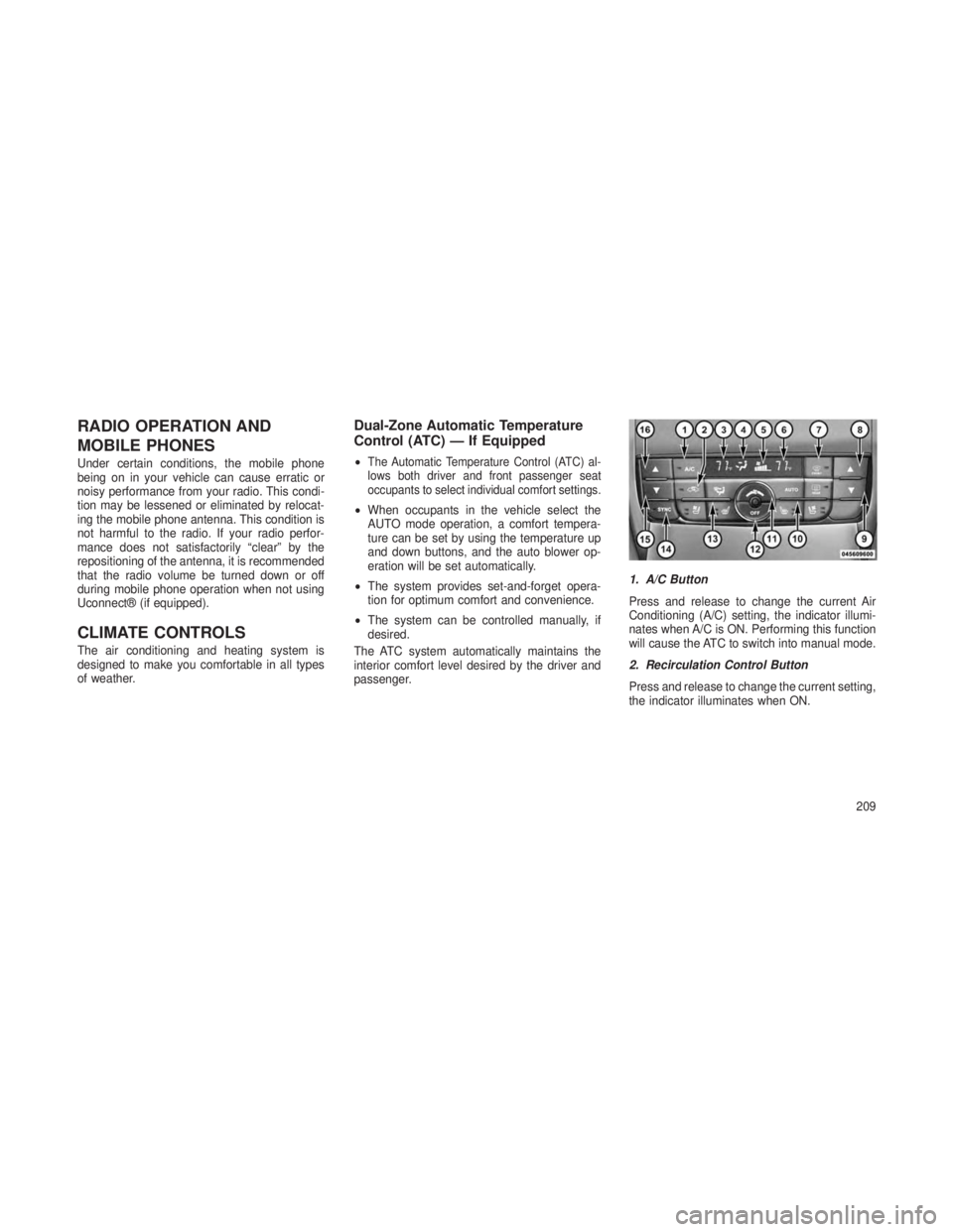
Dual-Zone Automatic Temperature
Control (ATC) — If Equipped
•The Automatic Temperature Control (ATC) al-
lows both driver and front passenger seat
occupants to select individual comfort settings.
•When occupants in the vehicle select the
AUTO mode operation, a comfort tempera-
ture can be set by using the temperature up
and down buttons, and the auto blower op-
eration will be set automatically.
• The system provides set-and-forget opera-
tion for optimum comfort and convenience.
• The system can be controlled manually, if
desired.
The ATC system automatically maintains the
interior comfort level desired by the driver and
passenger. 1. A/C Button
Press and release to change the current Air
Conditioning (A/C) setting, the indicator illumi-
nates when A/C is ON. Performing this function
will cause the ATC to switch into manual mode.
2. Recirculation Control Button
Press and release to change the current setting,
the indicator illuminates when ON.
209
Page 216 of 408

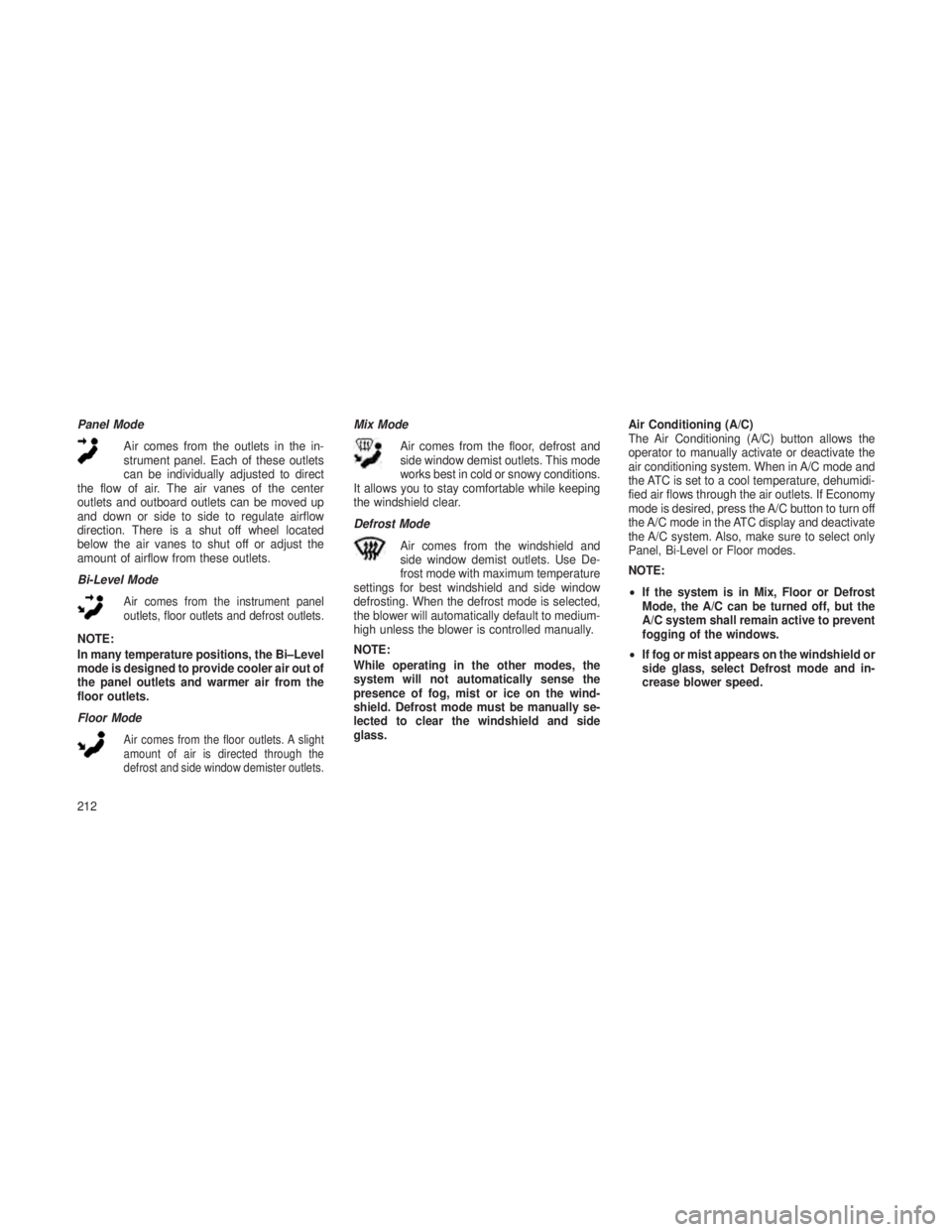
Panel ModeAir comes from the outlets in the in-
strument panel. Each of these outlets
can be individually adjusted to direct
the flow of air. The air vanes of the center
outlets and outboard outlets can be moved up
and down or side to side to regulate airflow
direction. There is a shut off wheel located
below the air vanes to shut off or adjust the
amount of airflow from these outlets.
Bi-Level Mode
Air comes from the instrument panel
outlets, floor outlets and defrost outlets.
NOTE:
In many temperature positions, the Bi–Level
mode is designed to provide cooler air out of
the panel outlets and warmer air from the
floor outlets.
Floor Mode
Air comes from the floor outlets. A slight
amount of air is directed through the
defrost and side window demister outlets.
Mix Mode
Air comes from the floor, defrost and
side window demist outlets. This mode
works best in cold or snowy conditions.
It allows you to stay comfortable while keeping
the windshield clear.
Defrost Mode
Air comes from the windshield and
side window demist outlets. Use De-
frost mode with maximum temperature
settings for best windshield and side window
defrosting. When the defrost mode is selected,
the blower will automatically default to medium-
high unless the blower is controlled manually.
NOTE:
While operating in the other modes, the
system will not automatically sense the
presence of fog, mist or ice on the wind-
shield. Defrost mode must be manually se-
lected to clear the windshield and side
glass. Air Conditioning (A/C)
The Air Conditioning (A/C) button allows the
operator to manually activate or deactivate the
air conditioning system. When in A/C mode and
the ATC is set to a cool temperature, dehumidi-
fied air flows through the air outlets. If Economy
mode is desired, press the A/C button to turn off
the A/C mode in the ATC display and deactivate
the A/C system. Also, make sure to select only
Panel, Bi-Level or Floor modes.
NOTE:
•
If the system is in Mix, Floor or Defrost
Mode, the A/C can be turned off, but the
A/C system shall remain active to prevent
fogging of the windows.
• If fog or mist appears on the windshield or
side glass, select Defrost mode and in-
crease blower speed.
212
Page 217 of 408

Recirculation ControlWhen outside air contains smoke,
odors, or high humidity, or if rapid
cooling is desired, you may wish to
recirculate interior air by pressing
the Recirculation control button.
Recirculation mode should only be
used temporarily. The recirculation LED will
illuminate when this button is selected. Push the
button a second time to turn off the Recircula-
tion mode LED and allow outside air into the
vehicle.
NOTE:
In cold weather, use of Recirculation mode
may lead to excessive window fogging. The
Recirculation mode is not allowed in the
Defrost mode to improve window clearing
operation. Recirculation will be disabled au-
tomatically if this mode is selected.Operating Tips
Window Fogging
Windows will fog on the inside when the humid-
ity inside the vehicle is high. This often occurs in
mild or cool temperatures when it’s rainy or
humid. In most cases, turning the air condition-
ing (pressing the A/C button) on will clear the
fog. Adjust the temperature control, air direc-
tion, and blower speed to maintain comfort.
As the temperature gets colder, it may be
necessary to direct air onto the windshield.
Adjust the temperature control and blower
speed to maintain comfort. Higher blower
speeds will reduce fogging. Interior fogging on
the windshield can be quickly removed by se-
lecting the Defrost mode.
Regular cleaning of the inside of the windows
with a non-filming cleaning solution (vinegar
and water works very well) will help prevent
contaminates (cigarette smoke, perfumes, etc.)
from sticking to the windows. Contaminates
increase the rate of window fogging. Summer Operation
NOTE:
In some cases during high temperature
trailer tow operation the Air Conditioning
system performance may be reduced. This
is to help protect the engine from overheat-
ing during the high load condition.
Your air conditioning system is also equipped
with an automatic recirculation system. When
the system senses a heavy load or high heat
conditions, it may use partial Recirculation A/C
mode to provide additional comfort.
Winter Operation
When operating the system during the winter
months, make sure the air intake, located di-
rectly in front of the windshield, is free of ice,
slush, snow, or other obstructions.
Vacation/Storage
Any time you store your vehicle or keep it out of
service (i.e., vacation) for two weeks or more,
run the air conditioning system at idle for about
five minutes in fresh air with the blower setting
in high. This will ensure adequate system lubri-
cation to minimize the possibility of compressor
damage when the system is started again.
213
Page 289 of 408

Pin
Number Function Wire
Color
11
aReturn for Contact (Pin) 10 Yellow/
Brown
12 Reserve for Future Allocation –
13
aReturn for Contact (Pin) 9 Red/
Brown
NOTE:
The allocation pin 12 has been changed
from “Coding for coupled Trailer” to
“Reserve for Future Allocation.”
aThe three return circuits shall not be
connected electrically in the trailer.
bThe rear position registration plate illumi-
nation device shall be connected such
that no light of the device has a common
connection with both pins 5 and 7.
Towing TipsBefore setting out on a trip, practice turning,
stopping and backing the trailer in an area away
from heavy traffic.
Automatic Transmission
The DRIVE range can be selected when towing.
The transmission controls include an adaptive
drive strategy to avoid frequent shifting when
towing. However, if frequent shifting does occur
while in DRIVE, select TOW mode, or use the
AutoStick® shift control to select a lower gear.
NOTE:
Using TOW mode or selecting a lower gear
while operating the vehicle under heavy load-
ing conditions, will improve performance and
extend transmission life by reducing exces-
sive shifting and heat buildup. This action will
also provide better engine braking.
If you REGULARLY tow a trailer for more than
45 minutes of continuous operation, then change
the transmission fluid and filter(s) as specified for
"police, taxi, fleet, or frequent trailer towing. Refer
to the “Maintenance Schedule” for the proper
maintenance intervals.
Electronic Speed Control – If Equipped
• Do not use in hilly terrain or with heavy loads.
• When using the speed control, if you experi-
ence speed drops greater than 10 mph
(16 km/h), disengage until you can get back
to cruising speed.
• Use speed control in flat terrain and with light
loads to maximize fuel efficiency.
Cooling System
To reduce potential for engine and transmission
overheating, take the following actions:
City Driving
When stopped for short periods of time, shift the
transmission into NEUTRAL and increase en-
gine idle speed.
Highway Driving
Reduce speed.
Air Conditioning
Turn off temporarily.
285
Page 320 of 408

Maintenance-Free BatteryYour vehicle is equipped with a maintenance-
free battery. You will never have to add water,
nor is periodic maintenance required.
WARNING!
•Battery fluid is a corrosive acid solution
and can burn or even blind you. Do not
allow battery fluid to contact your eyes,
skin, or clothing. Do not lean over a battery
when attaching clamps. If acid splashes in
eyes or on skin, flush the area immediately
with large amounts of water. Refer to
“Jump-Starting Procedures” in “What To
Do In Emergencies” for further information.
• Battery gas is flammable and explosive.
Keep flame or sparks away from the bat-
tery. Do not use a booster battery or any
other booster source with an output
greater than 12 Volts. Do not allow cable
clamps to touch each other.
(Continued)
WARNING!(Continued)
•Battery posts, terminals, and related ac-
cessories contain lead and lead com-
pounds. Wash hands after handling.
CAUTION!
•It is essential when replacing the cables on
the battery that the positive cable is at-
tached to the positive post and the nega-
tive cable is attached to the negative post.
Battery posts are marked positive (+) and
negative (-) and are identified on the bat-
tery case. Cable clamps should be tight on
the terminal posts and free of corrosion.
• If a “fast charger” is used while the battery
is in the vehicle, disconnect both vehicle
battery cables before connecting the char-
ger to the battery. Do not use a “fast
charger” to provide starting voltage.
Air Conditioner MaintenanceFor best possible performance, your air condi-
tioner should be checked and serviced by an
authorized dealer at the start of each warm
season. This service should include cleaning of
the condenser fins and a performance test.
Drive belt condition should also be checked at
this time.
CAUTION!
Do not use chemical flushes in your air
conditioning system as the chemicals can
damage your air conditioning components.
Such damage is not covered by the New
Vehicle Limited Warranty.
316
Page 321 of 408

WARNING!
•Use only refrigerants and compressor lu-
bricants approved by the manufacturer for
your air conditioning system. Some unap-
proved refrigerants are flammable and can
explode, injuring you. Other unapproved
refrigerants or lubricants can cause the
system to fail, requiring costly repairs.
• The air conditioning system contains re-
frigerant under high pressure. To avoid risk
of personal injury or damage to the sys-
tem, adding refrigerant or any repair re-
quiring lines to be disconnected should be
done by an experienced repairman.
NOTE:
Use only manufacturer approved A/C Sys-
tem Sealers, Stop Leak Products, Seal Con-
ditioners, Compressor Oil, and Refrigerants. Refrigerant Recovery And Recycling
R-134a Air Conditioning Refrigerant is a hydro-
fluorocarbon (HFC) that is endorsed by the
Environmental Protection Agency and is an
ozone-saving product. However, the manufac-
turer recommends that air conditioning service
be performed by authorized dealer or other
service facilities using recovery and recycling
equipment.
NOTE:
Use only manufacturer approved A/C sys-
tem sealers, stop leak products, seal condi-
tioners, compressor oil, and refrigerants.
A/C Air Filter
Refer to the “Maintenance Schedule” for the
proper maintenance intervals.
WARNING!
Do not remove the A/C air filter while the
blower is operating or personal injury may
result.The A/C air filter is located in the fresh air inlet
behind the glove box. Perform the following
procedure to replace the filter:
1. Open the glove compartment and remove all
contents.
2. Push in on the sides of the glove compart-
ment and lower the door.
3. Pivot the glove compartment downward.
4. Disengage the two retaining tabs that secure
the filter cover to the HVAC housing, and re-
move the cover.
A/C Air Filter Replacement
317
Page 328 of 408

Points To Remember
NOTE:
When the vehicle is stopped after a few
miles/kilometers of operation, you may ob-
serve vapor coming from the front of the
engine compartment. This is normally a re-
sult of moisture from rain, snow, or high
humidity accumulating on the radiator and
being vaporized when the thermostat opens,
allowing hot engine coolant (antifreeze) to
enter the radiator.
If an examination of your engine compartment
shows no evidence of radiator or hose leaks,
the vehicle may be safely driven. The vapor will
soon dissipate.
•Do not overfill the coolant expansion bottle.
• Check the coolant freeze point in the radiator
and in the coolant expansion bottle. If engine
coolant (antifreeze) needs to be added, the
contents of the coolant expansion bottle must
also be protected against freezing.
• If frequent engine coolant (antifreeze) addi-
tions are required, the cooling system should
be pressure tested for leaks. •
Maintain engine coolant (antifreeze) concen-
tration at a minimum of 50% OAT coolant
(conforming to MS-12106) and distilled water
for proper corrosion protection of your engine
which contains aluminum components.
• Make sure that the coolant expansion bottle
overflow hoses are not kinked or obstructed.
• Keep the front of the radiator clean. If your
vehicle is equipped with air conditioning,
keep the front of the condenser clean.
•
Do not change the thermostat for Summer or
Winter operation. If replacement is ever neces-
sary, install ONLY the correct type thermostat.
Other designs may result in unsatisfactory
engine coolant (antifreeze) performance, poor
gas mileage, and increased emissions.
Brake SystemIn order to assure brake system performance,
all brake system components should be in-
spected periodically. Refer to the “Maintenance
Schedule” for the proper maintenance intervals.
WARNING!
Riding the brakes can lead to brake failure
and possibly a collision. Driving with your
foot resting or riding on the brake pedal can
result in abnormally high brake tempera-
tures, excessive lining wear, and possible
brake damage. You would not have your full
braking capacity in an emergency.
Fluid Level Check – Brake Master Cylinder
The fluid level of the master cylinder should be
checked when performing under the hood ser-
vice, or immediately if the brake system warning
lamp indicates system failure.
The brake master cylinder has a plastic reser-
voir. On the outboard side of the reservoir, there
is a “MAX” dot and a “MIN” dot. The fluid level
must be kept within these two dots. Do not add
fluid above the MAX mark, because leakage
may occur at the cap.
324