Page 9 of 52
1-3 Warning and Indicator Lamp Information
1. READY Indicator (Green) 2. HV System Overheat Warning (Dot Matrix Liquid
Crystal Display)
3. Master Warning Lamp (Orange or Red) 4. Hybrid System Warning Lamp (Orange)Lamp Name
Icon Description
READ
Y Indicator
(Green) This lamp is on when the high voltage system is powered
up
and the vehicle is ready to drive.
Master Warning Lamp
(Orange or Red) This lamp is on when another warning lamp or message is
displayed
in the instrument cluster. AAYIA0010GB
9
Page 10 of 52
Lamp Name
Icon Description
Hybrid System Warning
Lamp *1
(Orange) This lamp is on or blinking when:
•
Malfunction has occurred in the high voltage system
and/or
• High voltage leak to vehicle chassis and/or
• Emergency shut-off system has been activated. The shut-off system activates in the following conditions:
– Front and side collisions in which the air bags are deployed.
– Certain rear collisions.
– Certain high voltage system malfunctions.
*1: When this lamp is ON, the READY Indicator will turn OFF.
10
Page 11 of 52

2. Basic High Voltage Information
2-1
Battery Information
The M35h HYBRID utilizes two batteries in order to supply both high and low voltage.
2-1.1 12V Battery • The M35h HYBRID contains a conventional lead-acid 12Vbattery.
• The 12V battery is located in the trunk, left of Li-ion battery, concealed by trim cover.
• The 12V battery is charged by the Li-ion battery through the DC/DC converter.
2-1.2 Li-ion Battery • The M35h HYBRID contains a Li-ion high voltage battery.
• The high voltage battery is mounted in the trunk areabehind the rear seat, enclosed in a metal case and
concealed by trim cover.
• The high voltage battery stores approximately 346 volts DC (400V max.) .
• The high voltage battery exhausts gases directly outside the vehicle through a vent hose.
• An air vent is located on the rear parcel shelf for battery cooling.
The high voltage battery supplies power to the following: • High voltage harnesses
• DC/DC converter
• Traction motor inverter
• Traction motor
• Electric air conditioner compressor AAYIA0064ZZ
AAYIA0065ZZ
AAYIA0066ZZ
11
Page 12 of 52
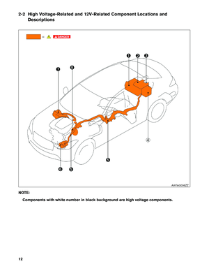
2-2 High Voltage-Related and 12V-Related Component Locations and
Descriptions
NO
TE:
Components with white number in black background are high voltage components. AAYIA0006ZZ
12
Page 13 of 52

Battery Trunk area (behind
rear seat back) The Li-ion battery stores and outputs DC
power (Maximum voltage 400V) needed to
propel the vehicle.")
No. Component
LocationDescription
a Lithium-ion
(Li-ion)
Battery Trunk area (behind
rear seat back) The Li-ion battery stores and outputs DC
power (Maximum voltage 400V) needed to
propel the vehicle.
b DC/DC Converter Trunk area (mounted
to top of Li-ion bat-
tery) The DC/DC converter reduces the voltage of
the Li-ion battery to provide power to the 12V
battery in order to operate the vehicle’s electric
components (headlights, audio system, etc.) .
c Service Plug Trunk area (below
parcel shelf; behind
access door in trim
panel) This is used to disable the high voltage system.
d 12V Battery Trunk area (below
parcel shelf; behind
trim panel left of
Li-ion battery) A lead-acid battery that supplies power to the
low voltage devices.
e High Voltage Har-
nesses Trunk area (on Li-ion
battery) , under floor
pan, engine com-
partment Orange-colored power cables carry high DC
voltage between each of the high voltage com-
ponents.
f Electric Air Condi-
tioner Compressor Engine compart-
ment (front driver
side) Air conditioner compressor
g Traction Motor
Inverter Engine compart-
ment (rear passen-
ger side) Converts the DC power stored in the Li-ion
battery to three-phase AC power and controls
motor torque (revolution) by regulating the
motor current. The inverter has a built in high
voltage capacitor.
h Traction Motor Built-into the trans-
mission Converts three-phase alternating current (AC)
power to drive power (torque) which propels
the vehicle.
2-3 Li-ion Battery Pack Specifications Li-ion Battery Specifications
Li-ion
battery voltage 346V (400V max.)
Number of Li-ion battery modules in the pack 12
Li-ion battery module voltage 28.8V each
Li-ion battery dimensions 33.35 x 17.83 x 15.43 in. (847 x 453 x 392 mm)
Li-ion battery weight 121.28 lbs (55 kg)
13
Page 14 of 52
2-4 High Voltage Safety Measures
Circuit insulation
The high voltage positive (+) and negative (-) circuits are insulated
from the metal chassis.
Reducing the risk of electrocution The high voltage components and harnesses have insulated cases or orange-colored coverings which provide insulation and easy identifica-
tion.
The high voltage battery case is electrically connected to the vehicle
ground. This connection helps protect the vehicle occupants and
vehicle dismantlers
from high voltage electrical shock.
IdentificationThe high voltage components are labeled “WARNING” similar to label
shown below. All high voltage harnesses are coated in orange.
2-4.1 Warning Label AAYIA0010ZZ
14
Page 15 of 52

2-5 High Voltage Safety System
The
high voltage safety system is intended to help keep vehicle occupants and emergency responders safe
from high voltage electricity. • A high voltage fuse provides short circuit protection inside the high voltage battery.
• The high voltage safety system is insulated from the metal chassis.
• Positive and negative high voltage power cables are connected to the high voltage battery and arecontrolled by normally open system main relays (SMR1 and SMR2) . When the vehicle is shut off,
the relays stop electrical flow from leaving the high voltage battery. However, it can take up to
ten (10) minutes for the high voltage capacitor to fully discharge. • The high voltage system and high voltage capacitor may remain powered for up to 10
minutes
after the vehicle is shut off.
• The high voltage battery retains high voltage at all times.
• A ground fault monitor continuously monitors for high voltage leakage to the metal chassis while the vehicle is running. If a malfunction is detected, the HPCM (hybrid powertrain control module) will
illuminate the hybrid system warning lamp in the instrument cluster.
•
The high voltage battery relays (SMR1 and SMR2) will automatically open to stop the electrical flow
in a frontal collision that is sufficient enough to activate the supplemental restraint system (SRS) . AAYIA0001GB
15
Page 16 of 52

2-6 High Voltage Circuit Shut-Off System
This
vehicle is equipped with a system to shut off the current from the Li-ion battery by the following
methods: Service plug
Positioned in the center area of the Li-ion battery, this plug shuts off the out-
put
of high voltage when manually removed.
System main relays Controlled by the ignition switch, these relays are powered by the 12V sys- tem and shut off high voltage from the Li-ion battery.
Emergency shut-off sys-
tem In the case of a collision (air bag deployment, etc.) or certain system malfunc-
tions this system shuts off the high voltage from the Li-ion battery.
2-7 Preventing Electrical Shock 1. If it is necessary to touch any of the high voltage harnesses or components, always wearappropriate PPE (refer to 3-1 Preparation Items) . Shut off the high voltage system by referring to
3-3.1 High Voltage System Shut-Down Procedure.
2.
To avoid the risk of electrocution, do not touch the inside of the Li-ion battery with bare hands
after shutting off the high voltage system. The Li-ion battery maintains charge even though the
high voltage system is shut down.
3. Cover damaged high voltage components with insulated tape.
16


 2. HV System Overheat Warning (Dot Matrix Liquid
Crystal Display)
3. Master Warning Lamp (Orange or Red) 4. Hybrid System Warning")
 This lamp is on or blinking when:
•
Malfunction has occurred in the high voltage system
and/or
• High voltage leak to vehicle cha")

 and negative (-) circuits are insulated
from the metal chassis.
Reducing the risk of electrocution The high voltage co")