2013 Hyundai Sonata Hybrid fuel
[x] Cancel search: fuelPage 384 of 425
Maintenance
70 7
Waxing
Wax the vehicle when water will no
longer bead on the paint.
Always wash and dry the vehicle before
waxing. Use a good quality liquid or
paste wax, and follow the manufacturer’s
instructions. Wax all metal trim to protect
it and to maintain its luster.
Removing oil, tar, and similar materials
with a spot remover will usually strip the
wax from the finish. Be sure to re-wax
these areas even if the rest of the vehicle
does not yet need waxing.Finish damage repair
Deep scratches or stone chips in the
painted surface must be repaired
promptly. Exposed metal will quickly rust
and may develop into a major repair
expense.
✽ ✽
NOTICE
If your vehicle is damaged and requires
any metal repair or replacement, be sure
the body shop applies anti-corrosion
materials to the parts repaired or
replaced.
Bright-metal maintenance
To remove road tar and insects, use a
tar remover, not a scraper or other
sharp object.
To protect the surfaces of bright-metal
parts from corrosion, apply a coating of
wax or chrome preservative and rub to
a high luster.
During winter weather or in coastal
areas, cover the bright metal parts with
a heavier coating of wax or preserva-
tive. If necessary, coat the parts with
non-corrosive petroleum jelly or other
protective compound.
Underbody maintenance
Corrosive materials used for ice and
snow removal and dust control may col-
lect on the underbody. If these materials
are not removed, accelerated rusting can
occur on underbody parts such as the
fuel lines, frame, floor pan and exhaust
system, even though they have been
treated with rust protection.
Thoroughly flush the vehicle underbody
and wheel openings with lukewarm or
cold water once a month, after off-road
driving and at the end of each winter. Pay
special attention to these areas because
it is difficult to see all the mud and dirt. It
will do more harm than good to wet down
the road grime without removing it. The
lower edges of doors, rocker panels, and
frame members have drain holes that
should not be allowed to clog with dirt;
trapped water in these areas can cause
rusting.
CAUTION
Wiping dust or dirt off the body
with a dry cloth will scratch the
finish.
Do not use steel wool, abrasive
cleaners, or strong detergents
containing highly alkaline or
caustic agents on chrome-plated
or anodized aluminum parts. This
may result in damage to the pro-
tective coating and cause discol-
oration or paint deterioration.
Page 389 of 425
775
Maintenance
EMISSION CONTROL SYSTEM
The emission control system of your
vehicle is covered by a written limited
warranty. Please see the warranty infor-
mation contained in the Owner’s
Handbook & Warranty Information book-
let in your vehicle.
Your vehicle is equipped with an emis-
sion control system to meet all applicable
emission regulations.
There are three emission control sys-
tems, as follows.
(1) Crankcase emission control system
(2) Evaporative emission control system
(3) Exhaust emission control system
In order to assure the proper function of
the emission control systems, it is rec-
ommended that you have your car
inspected and maintained by an author-
ized HYUNDAI dealer in accordance with
the maintenance schedule in this manu-
al.Caution for the Inspection and
Maintenance Test (With Electronic
Stability Control (ESC) system)
To prevent the vehicle from misfir-
ing during dynamometer testing,
turn the Electronic Stability Control
(ESC) system off by pressing the
ESC switch.
After dynamometer testing is com-
pleted, turn the ESC system back on
by pressing the ESC switch again.
1. Crankcase emission control
system
The positive crankcase ventilation sys-
tem is employed to prevent air pollution
caused by blow-by gases being emitted
from the crankcase. This system supplies
fresh filtered air to the crankcase through
the air intake hose. Inside the crankcase,
the fresh air mixes with blow-by gases,
which then pass through the PCV valve
into the induction system.
2. Evaporative emission control
(including ORVR: Onboard
Refueling Vapor Recovery)
system
The Evaporative Emission Control
System is designed to prevent fuel vapors
from escaping into the atmosphere.
(The ORVR system is designed to allow
the vapors from the fuel tank to be
loaded into a canister while refueling at
the gas station, preventing the escape of
fuel vapors into the atmosphere.)
Canister
Fuel vapors generated inside the fuel
tank are absorbed and stored in the
onboard canister. When the engine is
running, the fuel vapors absorbed in the
canister are drawn into the surge tank
through the purge control solenoid valve.
Purge Control Solenoid Valve (PCSV)
The purge control solenoid valve is con-
trolled by the Engine Control Module
(ECM); when the engine coolant tempera-
ture is low during idling, the PCSV closes
so that evaporated fuel is not taken into
the engine. After the engine warms-up
during ordinary driving, the PCSV opens
to introduce evaporated fuel to the engine.
Page 391 of 425
777
Maintenance
Do not operate the engine in confined
or closed areas (such as garages) any
more than what is necessary to move
the vehicle in or out of the area.
When the vehicle is stopped in an
open area for more than a short time
with the engine running, adjust the
ventilation system (as needed) to draw
outside air into the vehicle.
Never sit in a parked or stopped vehi-
cle for any extended time with the
engine running.
When the engine stalls or fails to start,
excessive attempts to restart the
engine may cause damage to the
emission control system.Operating precautions for catalytic
converters (if equipped)
Your vehicle is equipped with a catalytic
converter emission control device.
Therefore, the following precautions
must be observed:
Use only UNLEADED FUEL for gaso-
line engines.
Do not operate the vehicle when there
are signs of engine malfunction, such
as misfire or a noticeable loss of per-
formance. Do not misuse or abuse the engine.
Examples of misuse are coasting with
the ignition off and descending steep
grades in gear with the ignition off.
Do not operate the engine at high idle
speed for extended periods (5 minutes
or more).
Do not modify or tamper with any part
of the engine or emission control sys-
tem. All inspections and adjustments
must be made by an authorized
HYUNDAI dealer.
Avoid driving with a extremely low fuel
level. Running out of fuel could cause
the engine to misfire, damaging the
catalytic converter.
Failure to observe these precautions
could result in damage to the catalytic
converter and to your vehicle.
Additionally, such actions could void your
warranties.
WARNING- Fire
A hot exhaust system can ignite
flammable items under your vehi-
cle. Do not park, idle, or drive the
vehicle over or near flammable
objects, such as grass, vegetation,
paper, leaves, etc.
Page 397 of 425
85
Specifications, Consumer information, Reporting safety defects
RECOMMENDED LUBRICANTS AND CAPACITIES
To help achieve proper engine and powertrain performance and durability, use only lubricants of the proper quality.
The correct lubricants also help promote engine efficiency that results in improved fuel economy.
These lubricants and fluids are recommended for use in your vehicle.
*1Refer to the recommended SAE viscosity numbers on the next page.
*2Engine oils labeled Energy Conserving Oil are now available. Along with other additional benefits, they contribute to fuel economy by reducing
the amount of fuel necessary to overcome engine friction. Often, these improvements are difficult to measure in everyday driving, but in a year’s
time, they can offer significant cost and energy savings.
*
3If the API service SM engine oil is not available in your country, you are able to use API service SL.
LubricantVolumeClassification
Engine oil *1 *2 (drain and refill)
Recommends
4.76 US qt. (4.5 l)API Service SM*3,
ILSAC GF-4 or above
Automatic transaxle fluid6.97 US qt. (6.6 l)
MICHANG ATF SP-IV, SK ATF SP-IV
NOCA ATF SP-IV, HYUNDAI genuine ATF SP-IV or other
brands meeting the above specification approved by
Hyundai Motor Co.,
Coolant 6.97~7.29 US qt.
(6.6~6.9 l)Mixture of antifreeze and water (Ethylene glycol base
coolant for aluminum radiator)
Inverter coolant2.39 US qt. (2.26 l)Mixture of antifreeze and water (Ethylene glycol base
coolant for aluminum radiator)
Brake fluid0.7~0.8 US qt.
(0.7~0.8 l)FMVSS116 DOT-3 or DOT-4
Fuel17.2 US gal. (65 l)Unleaded gasoline
Page 398 of 425
Specifications, Consumer information, Reporting safety defects
6 8
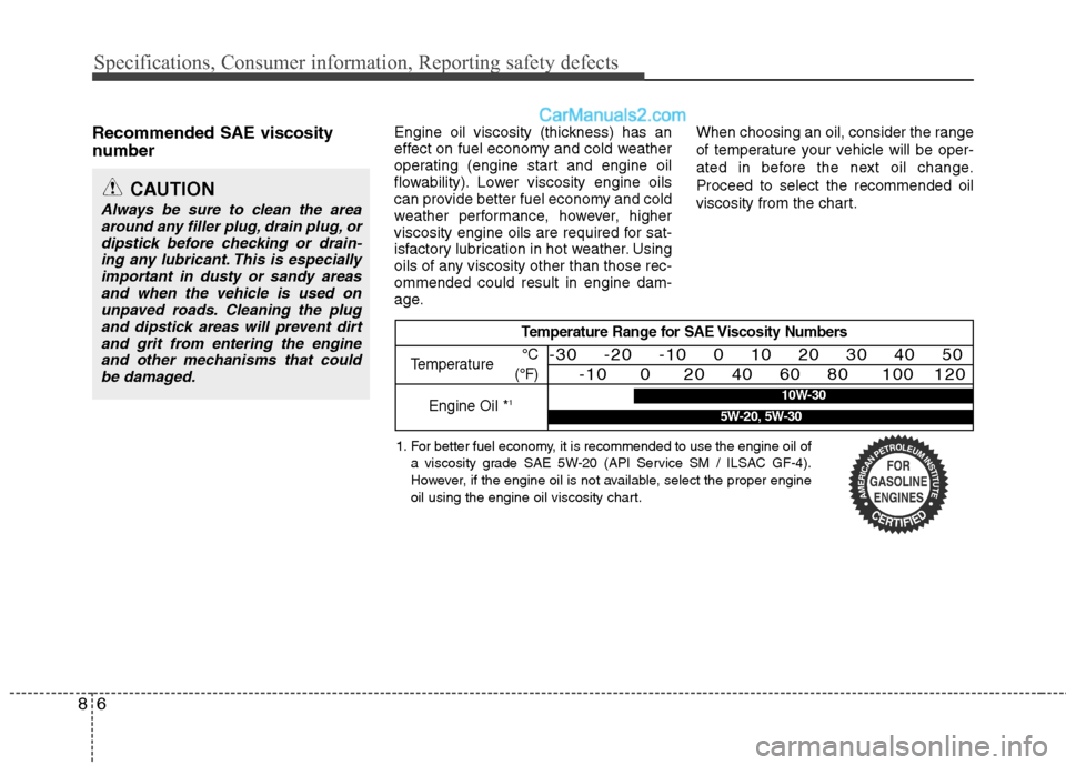
Recommended SAE viscosity
number Engine oil viscosity (thickness) has an
effect on fuel economy and cold weather
operating (engine start and engine oil
flowability). Lower viscosity engine oils
can provide better fuel economy and cold
weather performance, however, higher
viscosity engine oils are required for sat-
isfactory lubrication in hot weather. Using
oils of any viscosity other than those rec-
ommended could result in engine dam-
age.When choosing an oil, consider the range
of temperature your vehicle will be oper-
ated in before the next oil change.
Proceed to select the recommended oil
viscosity from the chart.
CAUTION
Always be sure to clean the area
around any filler plug, drain plug, or
dipstick before checking or drain-
ing any lubricant. This is especially
important in dusty or sandy areas
and when the vehicle is used on
unpaved roads. Cleaning the plug
and dipstick areas will prevent dirt
and grit from entering the engine
and other mechanisms that could
be damaged.
Temperature Range for SAE Viscosity Numbers
Temperature
Engine Oil *
1
°C
(°F)-30 -20 -10 0 10 20 30 40 50
-10 0 20 40 60 80 100 120
1. For better fuel economy, it is recommended to use the engine oil of
a viscosity grade SAE 5W-20 (API Service SM / ILSAC GF-4).
However, if the engine oil is not available, select the proper engine
oil using the engine oil viscosity chart.
10W-30
5W-20, 5W-30
Page 404 of 425
H2
The Hyundai Hybrid Electric Vehicle
(HEV) uses a gasoline engine and an
electric motor for power. The electric
motor is run from a 280V high voltage
HEV battery.
Depending on the driving conditions,
the HEV computer decides whether to
use the engine or use the electric
motor or even both at times.
Fuel is saved when the engine is not
running at idle or when the vehicle is
driven by the electric motor from the
HEV battery.
The HEV battery charge must be
maintained for the times when the
engine acts as a generator, such as
when stopped at idle. Charging also
occurs when decelerating or by
regenerative braking.Display of Hybrid system
Many displays provide information about
the hybrid system, such as, ECO level
and ECO score.
Through the ECO LEVEL, the driver can
understand the benefits of economical
driving.
If the driver is using economical driving
techniques, the ECO LEVEL rises. This
means the CO2 emissions are reduced.
In TOTAL ECO SCORE, when you reach
the maximum step of ECO LEVEL, the
ECO system calculates the score and
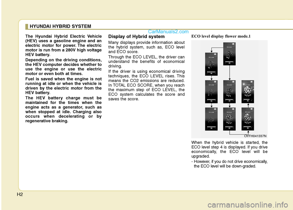
saves the score.ECO level display flower mode.1
When the hybrid vehicle is started, the
ECO level step 4 is displayed. If you drive
economically, the ECO level will be
upgraded.
- However, if you do not drive economically,
the ECO level will be down-graded.
HYUNDAI HYBRID SYSTEM
OYFH041337N
Page 416 of 425
H14
When the hybrid vehicle shuts off
When the high voltage battery is dis-
charged, or the 12-volt battery is dis-
charged, or the fuel tank is empty, the
hybrid system may not operate while
driving. If the Hybrid system cannot oper-
ate, do the following:
1. Reduce the vehicle speed gradually.
Pull your vehicle off the road in a safe
area.
2. Shift the transmission into "P" position.
3. Turn on the hazard warning flashers.
4. Set the start button at OFF, and try to
start the Hybrid system by applying the
brake pedal and pushing the Engine
Start/Stop button.
5. If the Hybrid system will not operate,
refer to "EMERGENCY STARTING" in
chapter 6.
If you try to jump start the vehicle, confirm
the fuel level and exact procedure of jump
start. For details, see the "EMERGENCY
STARTING" section in chapter 6. If the
fuel level is low, do not try to drive the
vehicle on battery power. The high volt-
age battery may be discharged and the
Hybrid system will turn off.
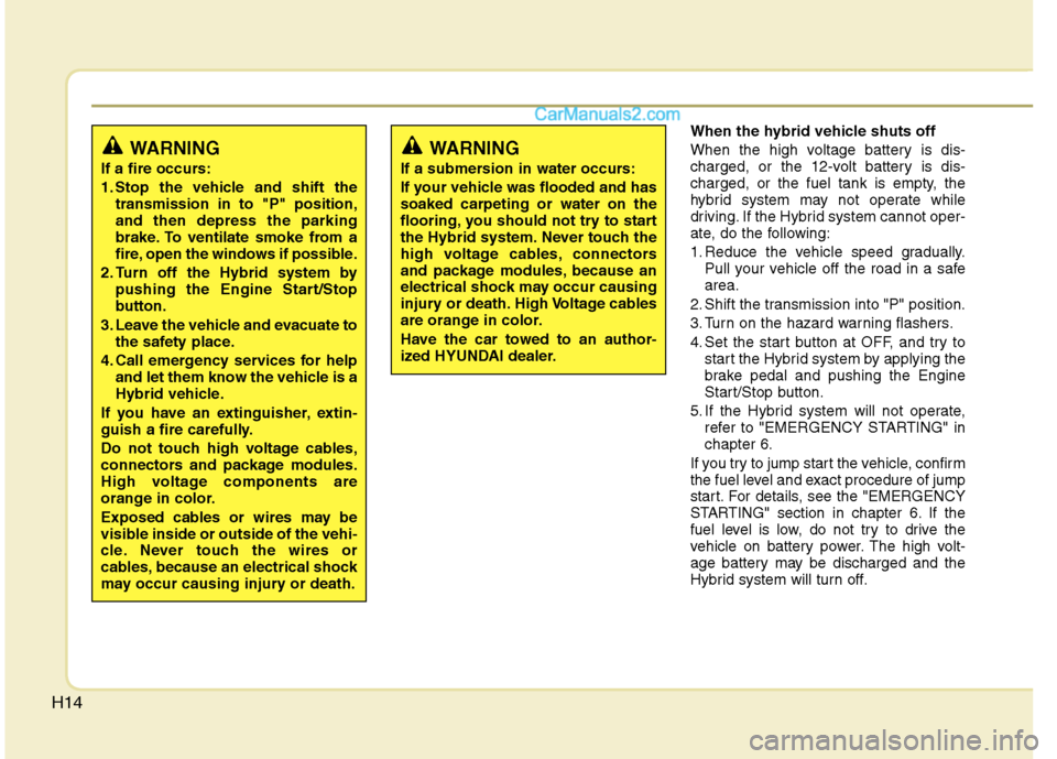
WARNING
If a fire occurs:
1. Stop the vehicle and shift the
transmission in to "P" position,
and then depress the parking
brake. To ventilate smoke from a
fire, open the windows if possible.
2. Turn off the Hybrid system by
pushing the Engine Start/Stop
button.
3. Leave the vehicle and evacuate to
the safety place.
4. Call emergency services for help
and let them know the vehicle is a
Hybrid vehicle.
If you have an extinguisher, extin-
guish a fire carefully.
Do not touch high voltage cables,
connectors and package modules.
High voltage components are
orange in color.
Exposed cables or wires may be
visible inside or outside of the vehi-
cle. Never touch the wires or
cables, because an electrical shock
may occur causing injury or death.
WARNING
If a submersion in water occurs:
If your vehicle was flooded and has
soaked carpeting or water on the
flooring, you should not try to start
the Hybrid system. Never touch the
high voltage cables, connectors
and package modules, because an
electrical shock may occur causing
injury or death. High Voltage cables
are orange in color.
Have the car towed to an author-
ized HYUNDAI dealer.
Page 420 of 425
Index
4I
ECO GUIDE gauge ·······················································4-43
Economical operation ····················································5-28
Electric chromic mirror (ECM) with HomeLink system··4-31
Electric power steering ··················································4-29
Electronic stability control (ESC) ·································5-19
Emergency starting ··························································6-6
Jump starting ·······························································6-6
Push starting ································································6-7
Emergency while driving·················································6-2
Emission control system ················································7-75
Crankcase emission control system ··························7-75
Evaporative emission control system························7-75
Exhaust emission control system ······························7-76
Engine ··············································································8-2
Engine compartment ················································2-4, 7-2
Engine compartment fuse ··············································7-52
Engine coolant ·······························································7-24
Engine number ·································································8-7
Engine oil ·······································································7-22
Engine overheats······························································6-8
Engine start/stop button ···················································5-5
Engine temperature gauge ·············································4-42
Engine will not start·························································6-5
Evaporative emission control system ····························7-75
Exhaust emission control system···································7-76
Explanation of scheduled maintenance items ···············7-19Exterior care···································································7-69
Flat tire (with spare tire) ················································6-14
Changing tires ···························································6-15
Compact spare tire ····················································6-20
Jack and tools ····························································6-14
Removing and storing the spare tire ·························6-15
Flat tire (with tire mobility kit) ·····································6-22
Components of the tire mobility kit ··························6-24
Technical data····························································6-27
Using the tire mobility kit ·········································6-25
Floor mat anchor(s) ······················································4-111
Fluid
Brakes fluid ·······························································7-27
Washer fluid ······························································7-28
Front passenger and rear seat 3-point system with
combination locking retractor ···································3-19
Front seat adjustment ·······················································3-4
Fuel filler lid ··································································4-22
Fuel gauge······································································4-43
Fuel requirements ····························································1-3
Fuse/relay panel description ··········································7-54
Fuses ··············································································7-50
Engine compartment fuse··········································7-52
Fuse/relay panel description······································7-54
Instrument panel fuse ················································7-51
Memory fuse ·····························································7-51
E
F