Page 231 of 563

The sensing system warns the driver of obstacles within a certain range
of the bumper area. The system turns on automatically whenever the
ignition is switched on.
When receiving a detection warning, the radio volume is reduced to a
predetermined level. After the warning goes away, the radio volume
returns to the previous level.
Using the Rear Sensing System
The rear sensors are only active when the transmission is inR.Asthe
vehicle moves closer to the obstacle, the rate of the audible warning
increases. When the obstacle is fewer than 12 inches (30 centimeters)
away, the warning sounds continuously. If a stationary or receding object
is detected farther than 12 inches (30 centimeters) from the side of the
vehicle, the tone sounds for only three seconds. Once the system detects
an object approaching, the warning sounds again.
A. Coverage area of up to 6 feet
(2 meters) from the rear bumper
(with a decreased coverage area at
the outer corners of the bumper).
The system detects certain objects while the transmission is inR:
•and moving toward a stationary object at a speed of 3 mph (5 km/h)
or less.
•but not moving, and a moving object is approaching the rear of the
vehicle at a speed of 3 mph (5 km/h) or less.
•and moving at a speed of less than 3 mph (5 km/h) and a moving
object is approaching the rear of the vehicle at a speed of less than
3 mph (5 km/h).
A
230Parking Aids
2013 F-250/350/450/550(f23)
Owners Guide gf, 1st Printing
USA(fus)
Page 233 of 563

2. Centerline: Helps align the center of the vehicle with an object (i.e. a
trailer).
Note:If the image comes on while the transmission is not in R
(Reverse), have the system inspected by your authorized dealer.
Note:When towing, the camera only sees what is being towed behind
the vehicle. This might not provide adequate coverage as it usually
provides in normal operation and some objects might not be seen. In
some vehicles, the guidelines may disappear once the trailer tow
connector is engaged.
Note:The default setting for the camera delay is off. Press the Settings
button found on the navigation screen (if equipped) to set the camera
delay feature to on or off.
Note:The camera may not operate correctly under the following
conditions:
•Nighttime or dark areas if one or both reverse lamps are not
operating.
•The camera’s view is obstructed by mud, water or debris. Clean the
lens with a soft, lint-free cloth and non-abrasive cleaner.
•The rear of the vehicle is hit or damaged, causing the camera to
become misaligned.
Guidelines and the Centerline
Note:Fixed guidelines are only available when the transmission is in R
(Reverse).
Note:The centerline is only available if fixed guidelines are on.
A. Rear bumper
B. Fixed guideline: Red zone
C. Fixed guideline: Yellow zone
D. Fixed guideline: Green zone
E. Centerline
The fixed guidelines fade in and out depending on the steering wheel
position.
A
E
D
C
B
232Parking Aids
2013 F-250/350/450/550(f23)
Owners Guide gf, 1st Printing
USA(fus)
Page 240 of 563

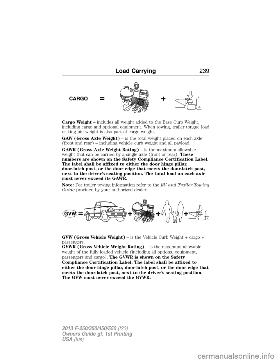
Cargo Weight– includes all weight added to the Base Curb Weight,
including cargo and optional equipment. When towing, trailer tongue load
or king pin weight is also part of cargo weight.
GAW (Gross Axle Weight)– is the total weight placed on each axle
(front and rear) – including vehicle curb weight and all payload.
GAWR (Gross Axle Weight Rating)– is the maximum allowable
weight that can be carried by a single axle (front or rear).These
numbers are shown on the Safety Compliance Certification Label.
The label shall be affixed to either the door hinge pillar,
door-latch post, or the door edge that meets the door-latch post,
next to the driver’s seating position. The total load on each axle
must never exceed its GAWR.
Note:For trailer towing information refer to theRV and Trailer Towing
Guideprovided by your authorized dealer.
GVW (Gross Vehicle Weight)– is the Vehicle Curb Weight + cargo +
passengers.
GVWR (Gross Vehicle Weight Rating)– is the maximum allowable
weight of the fully loaded vehicle (including all options, equipment,
passengers and cargo).The GVWR is shown on the Safety
Compliance Certification Label. The label shall be affixed to
either the door hinge pillar, door-latch post, or the door edge that
meets the door-latch post, next to the driver’s seating position.
The GVW must never exceed the GVWR.
Load Carrying239
2013 F-250/350/450/550(f23)
Owners Guide gf, 1st Printing
USA(fus)
Page 242 of 563

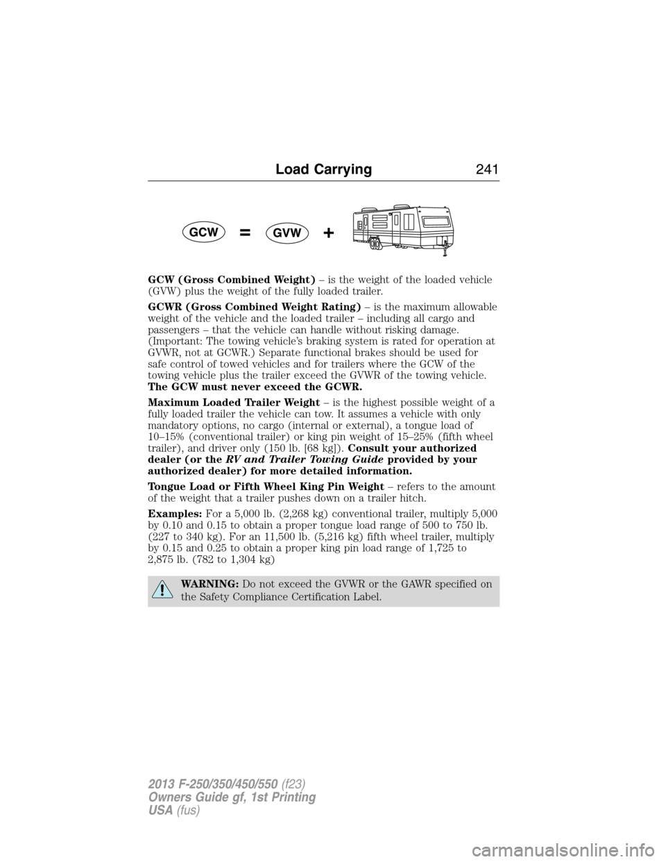
GCW (Gross Combined Weight)– is the weight of the loaded vehicle
(GVW) plus the weight of the fully loaded trailer.
GCWR (Gross Combined Weight Rating)– is the maximum allowable
weight of the vehicle and the loaded trailer – including all cargo and
passengers – that the vehicle can handle without risking damage.
(Important: The towing vehicle’s braking system is rated for operation at
GVWR, not at GCWR.) Separate functional brakes should be used for
safe control of towed vehicles and for trailers where the GCW of the
towing vehicle plus the trailer exceed the GVWR of the towing vehicle.
The GCW must never exceed the GCWR.
Maximum Loaded Trailer Weight– is the highest possible weight of a
fully loaded trailer the vehicle can tow. It assumes a vehicle with only
mandatory options, no cargo (internal or external), a tongue load of
10–15% (conventional trailer) or king pin weight of 15–25% (fifth wheel
trailer), and driver only (150 lb. [68 kg]).Consult your authorized
dealer (or theRV and Trailer Towing Guideprovided by your
authorized dealer) for more detailed information.
Tongue Load or Fifth Wheel King Pin Weight– refers to the amount
of the weight that a trailer pushes down on a trailer hitch.
Examples:For a 5,000 lb. (2,268 kg) conventional trailer, multiply 5,000
by 0.10 and 0.15 to obtain a proper tongue load range of 500 to 750 lb.
(227 to 340 kg). For an 11,500 lb. (5,216 kg) fifth wheel trailer, multiply
by 0.15 and 0.25 to obtain a proper king pin load range of 1,725 to
2,875 lb. (782 to 1,304 kg)
WARNING:Do not exceed the GVWR or the GAWR specified on
the Safety Compliance Certification Label.
Load Carrying241
2013 F-250/350/450/550(f23)
Owners Guide gf, 1st Printing
USA(fus)
Page 243 of 563

WARNING:Do not use replacement tires with lower load
carrying capacities than the original tires because they may lower
the vehicle’s GVWR and GAWR limitations. Replacement tires with a
higher limit than the original tires do not increase the GVWR and
GAWR limitations.
WARNING:Exceeding any vehicle weight rating limitation could
result in serious damage to the vehicle and/or personal injury.
Steps for determining the correct load limit:
1. Locate the statement “The combined weight of occupants and cargo
should never exceed XXX kg or XXX lb.” on your vehicle’s placard.
2. Determine the combined weight of the driver and passengers that will
be riding in your vehicle.
3. Subtract the combined weight of the driver and passengers from XXX
kg or XXX lb.
4. The resulting figure equals the available amount of cargo and luggage
load capacity. For example, if the “XXX” amount equals 1,400 lb. and
there will be five 150 lb. passengers in your vehicle, the amount of
available cargo and luggage load capacity is 650 lb. (1400-750 (5 x 150)
= 650 lb.). In metric units (635-340 (5 x 68) = 295 kg.)
5. Determine the combined weight of luggage and cargo being loaded on
the vehicle. That weight may not safely exceed the available cargo and
luggage load capacity calculated in Step 4.
6. If your vehicle will be towing a trailer, load from your trailer will be
transferred to your vehicle. Consult this manual to determine how this
reduces the available cargo and luggage load capacity of your vehicle.
The following gives you a few examples on how to calculate the available
amount of cargo and luggage load capacity:
•Suppose your vehicle has a 1400 lb. (635 kg) cargo and luggage
capacity. You decide to go golfing. Is there enough load capacity to
carry you, 4 of your friends and all the golf bags? You and four friends
average 220 lb. (99 kg) each and the golf bags weigh approximately
30 lb. (13.5 kg) each. The calculation would be: 1400 - (5 x 220) - (5
x 30) = 1400 - 1100 - 150 = 150 lb. Yes, you have enough load
capacity in your vehicle to transport four friends and your golf bags.
In metric units, the calculation would be: 635 kg - (5 x 99 kg) - (5 x
13.5 kg) = 635 - 495 - 67.5 = 72.5 kg.
242Load Carrying
2013 F-250/350/450/550(f23)
Owners Guide gf, 1st Printing
USA(fus)
Page 247 of 563

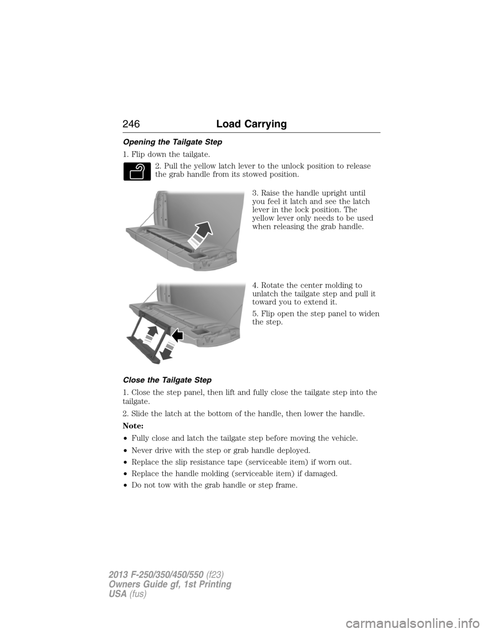
Opening the Tailgate Step
1. Flip down the tailgate.
2. Pull the yellow latch lever to the unlock position to release
the grab handle from its stowed position.
3. Raise the handle upright until
you feel it latch and see the latch
lever in the lock position. The
yellow lever only needs to be used
when releasing the grab handle.
4. Rotate the center molding to
unlatch the tailgate step and pull it
toward you to extend it.
5. Flip open the step panel to widen
the step.
Close the Tailgate Step
1. Close the step panel, then lift and fully close the tailgate step into the
tailgate.
2. Slide the latch at the bottom of the handle, then lower the handle.
Note:
•Fully close and latch the tailgate step before moving the vehicle.
•Never drive with the step or grab handle deployed.
•Replace the slip resistance tape (serviceable item) if worn out.
•Replace the handle molding (serviceable item) if damaged.
•Do not tow with the grab handle or step frame.
246Load Carrying
2013 F-250/350/450/550(f23)
Owners Guide gf, 1st Printing
USA(fus)
Page 248 of 563
BED EXTENDER (IF EQUIPPED)
Note:This feature is not intended for off-road usage.
Note:Make sure the locking pins and knobs are fully engaged when the
vehicle is in motion.
Note:Make sure all cargo is secured.
Note:The tailgate load must not exceed 150 pounds (68 kilograms)
when the vehicle is in motion.
Note:The bed extender should always be kept in the grocery mode or
stowed position with the tailgate closed when not being used for the
purpose of restraining cargo in the tailgate mode.
To open the bed extender into tailgate mode:
1. Pull the locking pin toward the
center of the vehicle.
2. Open the latches to release the
panels.
Load Carrying247
2013 F-250/350/450/550(f23)
Owners Guide gf, 1st Printing
USA(fus)
Page 249 of 563
3. Rotate the panels toward the
tailgate.
Repeat Steps 1–3 for the other side of the bed extender.
4. Connect the two panels, then
rotate both knobs a quarter-turn
clockwise to secure the panels.
5. Make sure the latch rod is
inserted into the tailgate hole and
the locking pins on both sides are
engaged into their holes in the
pick-up box.
6. Reverse steps for storage of the
bed extender.
To open the bed extender into
grocery mode, follow Steps 1–4 by
rotating the panels away from the
tailgate. Close the tailgate.
248Load Carrying
2013 F-250/350/450/550(f23)
Owners Guide gf, 1st Printing
USA(fus)