Page 3 of 157

Cruise Control 46
Usingcruisecontrol....................................46
Load Carrying 48
Vehicle loading........................................48
Towing 54
Trailertowing.........................................54
Wrecker towing.......................................59
Driving Hints 60
Economical driving.....................................60
Roadside Emergencies 62
Getting roadside assistance...............................62
Hazard flasher control..................................63
Jump-starting the vehicle................................64
Customer Assistance 67
Reporting safety defects (U.S. only)........................73
Reporting safety defects (Canada only)......................73
Fuses 74
Changing a fuse.......................................74
Fuse specification chart.................................75
Maintenance 83
General information....................................83
Under hood overview...................................84
Engine oil dipstick.....................................86
Engine oil check.......................................86
Engine coolant check...................................87
Automatic transmission fluid check.........................91
Fuel filter...........................................97
Battery .............................................98
Air filter(s).........................................100
2Table of Contents
2013 Motorhome(mot)
Owners Guide gf, 1st Printing
USA(fus)
Page 6 of 157
Symbol Description Symbol Description Symbol Description
Brake fluid –
non
petroleum
baseBrake systemCabin air
filter
Check fuel
capChild Safety
Door Lock
and UnlockChild seat
lower anchor
Child seat
tether anchorCruise
controlDo not open
when hot
Engine air
filterEngine
coolantEngine
coolant
temperature
Engine oilExplosive gasFan warning
Fasten safety
beltFront airbagFront fog
lamps
Fuel pump
resetFuse
compartmentHazard
warning
flasher
Heated rear
windowInterior
luggage
compartment
releaseJack
Lighting
controlLow tire
pressure
warningMaintain
correct fluid
level
Panic alarmParking aid
systemParking
brake system
Introduction5
2013 Motorhome(mot)
Owners Guide gf, 1st Printing
USA(fus)
Page 43 of 157

Brake-shift interlock
WARNING:To prevent vehicle movement when following this
procedure, park on a level surface, ensure parking brake is set,
and block the rear wheels.
WARNING:If your brake lamps are not working properly or if
you have disconnected the vehicle battery cables, the vehicle
brake lamps and hazard flashers may not properly warn traffic of a
vehicle breakdown or approaching danger, which can increase the risk
of serious injury or death. To minimize the risk of serious injury or
death, be aware of your surroundings, use other hazard signaling
devices if available, and move the vehicle to a safe location away from
traffic as soon as possible.
WARNING:Do not drive your vehicle until you verify that the
brake lamps are working.
WARNING:Always set the parking brake fully and make sure
the gearshift is latched in P (Park). Turn the ignition to the lock
position and remove the key whenever you leave your vehicle.
WARNING:If the parking brake is fully released, but the brake
warning lamp remains illuminated, the brakes may not be
working properly. See your authorized dealer.
The vehicle is equipped with a brake-shift interlock feature that prevents
the gearshift lever from being moved from P (Park) unless the brake
pedal is pressed.
If you cannot move the gearshift lever out of P (Park) position with the
ignition in the 4 (on) position and the brake pedal pressed, a
malfunction may have occurred. It is possible that a fuse has blown or
the vehicle’s brake lamps are not operating properly. Refer toFuses and
relaysin theRoadside Emergencieschapter. If the fuses and brake
lamps are working properly, and the vehicle still will not shift out of (P)
Park, see your authorized dealer for service.
42Transmission
2013 Motorhome(mot)
Owners Guide gf, 1st Printing
USA(fus)
Page 75 of 157
CHANGING A FUSE
Fuses
If electrical components in the vehicle
are not working, a fuse may have
blown. Blown fuses are identified by a
broken wire within the fuse. Check
the appropriate fuses before replacing
any electrical components.
Note:Always replace a fuse with one that has the specified amperage
rating. Using a fuse with a higher amperage rating can cause severe wire
damage and could start a fire.
Standard Fuse Amperage Rating and Color
COLOR
Fuse
ratingMini
fusesStandard
fusesMaxi
fusesCartridge
maxi
fusesFuse link
cartridge
2A Grey Grey — — —
3A Violet Violet — — —
4A Pink Pink — — —
5A Tan Tan — — —
7.5A Brown Brown — — —
10A Red Red — — —
15A Blue Blue — — —
20A Yellow Yellow Yellow Blue Blue
25A Natural Natural — Natural Natural
30A Green Green Green Pink Pink
40A — — Orange Green Green
50A — — Red Red Red
60A — — Blue Yellow Yellow
70A — — Tan — Brown
80A — — Natural Black Black
15
74Fuses
2013 Motorhome(mot)
Owners Guide gf, 1st Printing
USA(fus)
Page 76 of 157
FUSE SPECIFICATION CHART
Power Distribution Box
WARNING:Always disconnect the battery before servicing high
current fuses.
WARNING:To reduce risk of electrical shock, always replace the
cover to the power distribution box before reconnecting the
battery or refilling fluid reservoirs.
The power distribution box is located in the engine compartment. It has
high-current fuses that protect your vehicle’s main electrical systems
from overloads.
If the battery has been disconnected and reconnected, refer to
Changing the vehicle batteryin theMaintenancechapter.
19 29
18 28
17 27
16 26
15 25
14 24
13
11 12
910
78
56
34
1223
22
21
20
R6
R5
R4
R3
R2
R1DIODE2
DIODE1
Fuses75
2013 Motorhome(mot)
Owners Guide gf, 1st Printing
USA(fus)
Page 77 of 157

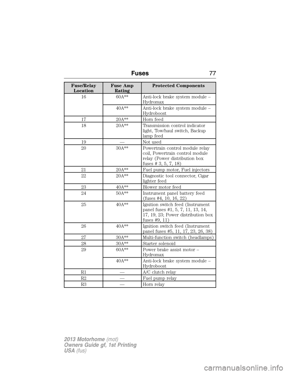
The high-current fuses are coded as follows:
Fuse/Relay
LocationFuse Amp
RatingProtected Components
1 5A* Power brake assist module –
Hydromax
2 10A* A/C compressor clutch
3 20A* A/C clutch relay coil, Mass air
flow sensor with intake air
temperature, Vapor management
valve, Engine heated exhaust gas
oxygen sensor #11 and #21,
Catalyst monitor sensor
4 5A* Powertrain control module
memory
5 20A* Powertrain control module power
6 20A* Park lamp feeds, Instrument panel
fuse #41, Warning chime module,
Trailer tow running lamp relay
coil, Instrument panel dimmer
module
7 20A* Ignition coils, Radio capacitors
8 30A* Hydromax – Anti-lock brake
system module
9 10A* Starter main relay coil, Starter
ground relay coil
10 20A* Daytime running lamps
11 20A* Fuel pump relay coil, Powertrain
control module power
12 25A* Trailer tow back-up lamps feed,
Instrument panel - backup lamp
feed
13 30A** Trailer tow electric brake
controller feed
14 60A** Instrument panel battery feed
(fuse #9, 15, 21)
15 20A** Trailer tow park lamps
76Fuses
2013 Motorhome(mot)
Owners Guide gf, 1st Printing
USA(fus)
Page 78 of 157

Fuse/Relay
LocationFuse Amp
RatingProtected Components
16 60A** Anti-lock brake system module –
Hydromax
40A** Anti-lock brake system module –
Hydroboost
17 20A** Horn feed
18 20A** Transmission control indicator
light, Tow/haul switch, Backup
lamp feed
19 — Not used
20 30A** Powertrain control module relay
coil, Powertrain control module
relay (Power distribution box
fuses#3,5,7,18)
21 20A** Fuel pump motor, Fuel injectors
22 20A** Diagnostic tool connector, Cigar
lighter feed
23 40A** Blower motor feed
24 50A** Instrument panel battery feed
(fuses #4, 10, 16, 22)
25 40A** Ignition switch feed (Instrument
panel fuses #1, 5, 7, 11, 13, 14,
17, 19, 23; Power distribution box
fuses #9, 11)
26 40A** Ignition switch feed (Instrument
panel fuses #5, 11, 17, 23, 26, 38)
27 30A** Multi-function switch (headlamps)
28 30A** Starter solenoid
29 60A** Power brake assist motor –
Hydromax
40A** Anti-lock brake system module –
Hydroboost
R1 — A/C clutch relay
R2 — Fuel pump relay
R3 — Horn relay
Fuses77
2013 Motorhome(mot)
Owners Guide gf, 1st Printing
USA(fus)
Page 79 of 157
Fuse/Relay
LocationFuse Amp
RatingProtected Components
R4 — Starter relay
R5 — Blower motor relay
R6 — Powertrain control module relay
Diode 1 — Fuel pump diode
Diode 2 — A/C clutch diode
* Mini Fuses ** Maxi Fuses
Diode and Relay Module
The module box is located by the power distribution box in front of the
radiator in the engine compartment.
The components are coded as follows:
Relay Location Description
1 One touch integrated start (ATO diode)
2 Not used
3 Not used
4 Daytime running lamps power relay
5 Hydromax – brake on/off signal isolating relay
6 Reverse lamps relay
7 Starter ground relay
8 Trailer tow parking lamps relay
1
4 5 7
6 8
2
3
78Fuses
2013 Motorhome(mot)
Owners Guide gf, 1st Printing
USA(fus)