2013 FORD EXPEDITION height
[x] Cancel search: heightPage 239 of 497

AIR SUSPENSION SYSTEM (IF EQUIPPED)
WARNING:On vehicles equipped with air suspension, turn the
air suspension and the ignition switch off prior to jacking,
hoisting or towing your vehicle.
The air suspension system is designed to improve ride, handling and
general vehicle performance during:
•Certain road conditions
•Steering maneuvers
•Braking
•Acceleration
This system keeps the rear of your vehicle at a constant level by
automatically adding air or releasing air from the springs. If you exceed
the load limit, the rear air suspension may not operate. The air
suspension system will stay active for 40 minutes after the ignition is
turned off to accommodate any load changes. (The air compressor may
run when the vehicle is off; this is normal.)
The air suspension system can be enabled or disabled through the
message center. Refer to theInformation Displayschapter.
If the system is off, the rear air suspension will not operate and will not
raise (pump) or lower (vent) while the vehicle is not moving. However, if
the system determines that the vehicle is low or high and needs to make
a height adjustment while driving at speeds above 15 mph (24 km/h), the
system will pump or vent as required. Normal vehicle operation does not
require any action by the driver.
Driving Aids239
2013 Expedition(exd)
Owners Guide gf, 1st Printing
USA(fus)
Page 254 of 497
The standard integrated hitch has two ratings depending on mode of
operation:
•Weight-carryingrequires a draw bar and hitch ball. The draw bar
supports all the vertical tongue load of the trailer.
•Weight-distributingrequires an aftermarket weight-distributing
system which includes draw bar, hitch ball, spring bars and snap-up
brackets. The vertical tongue load of the trailer is distributed between
the truck and the trailer by this system.
Mode Maximum Trailer
Weight - lb (kg)Maximum Tongue
Weight - lb (kg)
Weight-carrying 6000 (2721) 600 (272)
Weight-distributing 9200 (4173) 920 (417)
Note:These are hitch ratings only; actual vehicle ratings are dependent
on engine, transmission and axle combinations.
Weight-distributing Hitch – Vehicles without Air Suspension
WARNING:Do not adjust a weight-distributing hitch to any
position where the rear bumper of the vehicle is higher than it
was before attaching the trailer. Doing so will defeat the function of the
weight-distributing hitch, which may cause unpredictable handling, and
could result in serious personal injury.
When hooking-up a trailer using a weight-distributing hitch, always use
the following procedure:
1. Park the vehicle (without the trailer) on a level surface.
2. Measure the height of the top of the front wheel opening on the
fender, this is H1.
3. Attach the trailer to the vehicle without the weight distributing bars
connected.
4. Measure the height of the top of the front wheel opening on the
fender a second time, this is H2.
5. Install and adjust the tension in the weight distributing bars so that
the height of the front fender is approximately halfway between H1
and H2.
6. Check that the trailer is level. If not level, remove the trailer, adjust
the ball height accordingly, and repeat Steps 3–6.
254Towing
2013 Expedition(exd)
Owners Guide gf, 1st Printing
USA(fus)
Page 255 of 497
Weight-distributing Hitch – Vehicles with Air Suspension
WARNING:Do not adjust a weight-distributing hitch to any
position where the rear bumper of the vehicle is higher than it
was before attaching the trailer. Doing so will defeat the function of the
weight-distributing hitch, which may cause unpredictable handling, and
could result in serious personal injury.
When hooking-up a trailer using a weight-distributing hitch, always use
the following procedure:
1. Turn off easy entry / kneel feature if equipped.
2. Park the vehicle, without trailer and with the ignition on, on a level
surface with all doors closed for a few minutes to ensure that the air
suspension has settled.
3. Measure the height of the top of the front wheel opening on the
fender, this is H1.
4. Attach the trailer to the vehicle; do not install the weight distributing
bars at this time.
5. With the ignition on and all doors closed, let the vehicle with trailer
sit for a few minutes to let the air suspension re-settle.
6. With the trailer connected, but without weight distributing bars
connected, measure the height of the top of the front wheel opening
on the fender a second time, this is H2.
7. Install and adjust the tension in the weight distributing bars so that
the height of the front fender is approximately halfway between H1
and H2.
8. With the ignition on and all doors closed, let the vehicle, now with
trailer and weight distributing bars connected, sit for a few minutes
to let the air suspension re-settle.
9. Re-measure the height of the top of the front wheel opening,
repeating Steps 7-9 as necessary to obtain a fender height
approximately halfway between H1 and H2 after the air suspension
has settled.
10. Check that the trailer is level. If not level, remove the trailer, adjust
the ball height accordingly, and repeat Steps 4–10.
Safety Chains
Note:Do not attach safety chains to the bumper.
Always connect the trailer’s safety chains to the frame or hook retainers
of the vehicle hitch.
To connect the trailer’s safety chains, cross the chains under the trailer
tongue and allow enough slack for turning tight corners. Do not allow the
chains to drag on the ground.
Towing255
2013 Expedition(exd)
Owners Guide gf, 1st Printing
USA(fus)
Page 278 of 497
If your vehicle must be serviced while you are traveling or living in
Asia-Pacific Region, Sub-Saharan Africa, U.S. Virgin Islands, Central
America, the Caribbean, and Israel, contact the nearest authorized
dealer. If the authorized dealer cannot help you, contact:
FORD MOTOR COMPANY
FORD EXPORT OPERATIONS & GLOBAL INITIATIVES
1555 Fairlane Drive
Fairlane Business Park #3
Allen Park, Michigan 48101
U.S.A.
Telephone: (313) 594-4857
For customers in Guam, the Commonwealth of the Northern Mariana
Islands (CNMI), America Samoa, and the U.S. Virgin Islands, please feel
free to call our Toll-Free Number: (800) 841-FORD (3673).
FAX: (313) 390-0804
Email: [email protected]
If your vehicle must be serviced while you are traveling or living in
Puerto Rico, contact the nearest authorized dealer. If the authorized
dealer cannot help you, contact:
Ford International Business Development Inc.
Customer Relationship Center
P.O. Box 11957
Caparra Heights Station
San Juan, Puerto Rico 00922-1957
Telephone: (800) 841-FORD (3673)
FAX: (313) 390-0804
Email: [email protected]
www.ford.com.pr
If your vehicle must be serviced while you are traveling or living in the
Middle East, contact the nearest authorized dealer. If the authorized
dealer cannot help you, contact:
Ford Middle East
Customer Relationship Center
P.O. Box 21470
Dubai, United Arab Emirates
Telephone: +971 4 3326084
Toll-Free Number for the Kingdom of Saudi Arabia: 800 8971409
Local Telephone Number for Kuwait: 24810575
FAX: +971 4 3327299
Email: [email protected]
www.me.ford.com
278Customer Assistance
2013 Expedition(exd)
Owners Guide gf, 1st Printing
USA(fus)
Page 306 of 497
ADJUSTING THE HEADLAMPS
The headlamps on your vehicle are properly aimed at the assembly plant.
If your vehicle has been in an accident, the alignment of your headlamps
should be checked by your authorized dealer.
Vertical Aim Adjustment
Before aim adjustment, disable the air suspension system. Refer to
Message centerin theDriver Controlschapter.
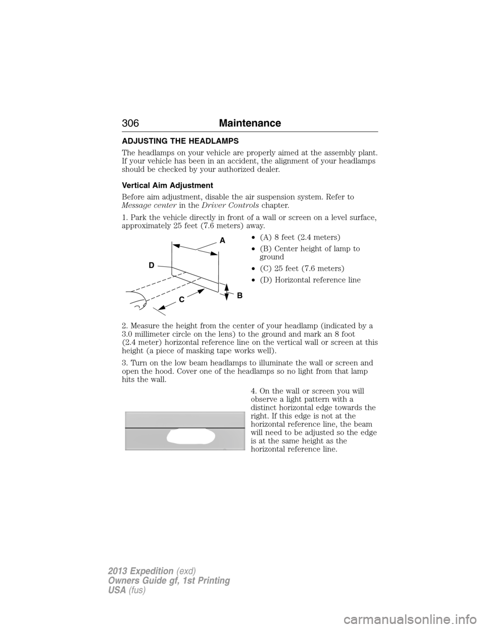
1. Park the vehicle directly in front of a wall or screen on a level surface,
approximately 25 feet (7.6 meters) away.
•(A) 8 feet (2.4 meters)
•(B) Center height of lamp to
ground
•(C) 25 feet (7.6 meters)
•(D) Horizontal reference line
2. Measure the height from the center of your headlamp (indicated by a
3.0 millimeter circle on the lens) to the ground and mark an 8 foot
(2.4 meter) horizontal reference line on the vertical wall or screen at this
height (a piece of masking tape works well).
3. Turn on the low beam headlamps to illuminate the wall or screen and
open the hood. Cover one of the headlamps so no light from that lamp
hits the wall.
4. On the wall or screen you will
observe a light pattern with a
distinct horizontal edge towards the
right. If this edge is not at the
horizontal reference line, the beam
will need to be adjusted so the edge
is at the same height as the
horizontal reference line.
C
A
B
D
306Maintenance
2013 Expedition(exd)
Owners Guide gf, 1st Printing
USA(fus)
Page 329 of 497
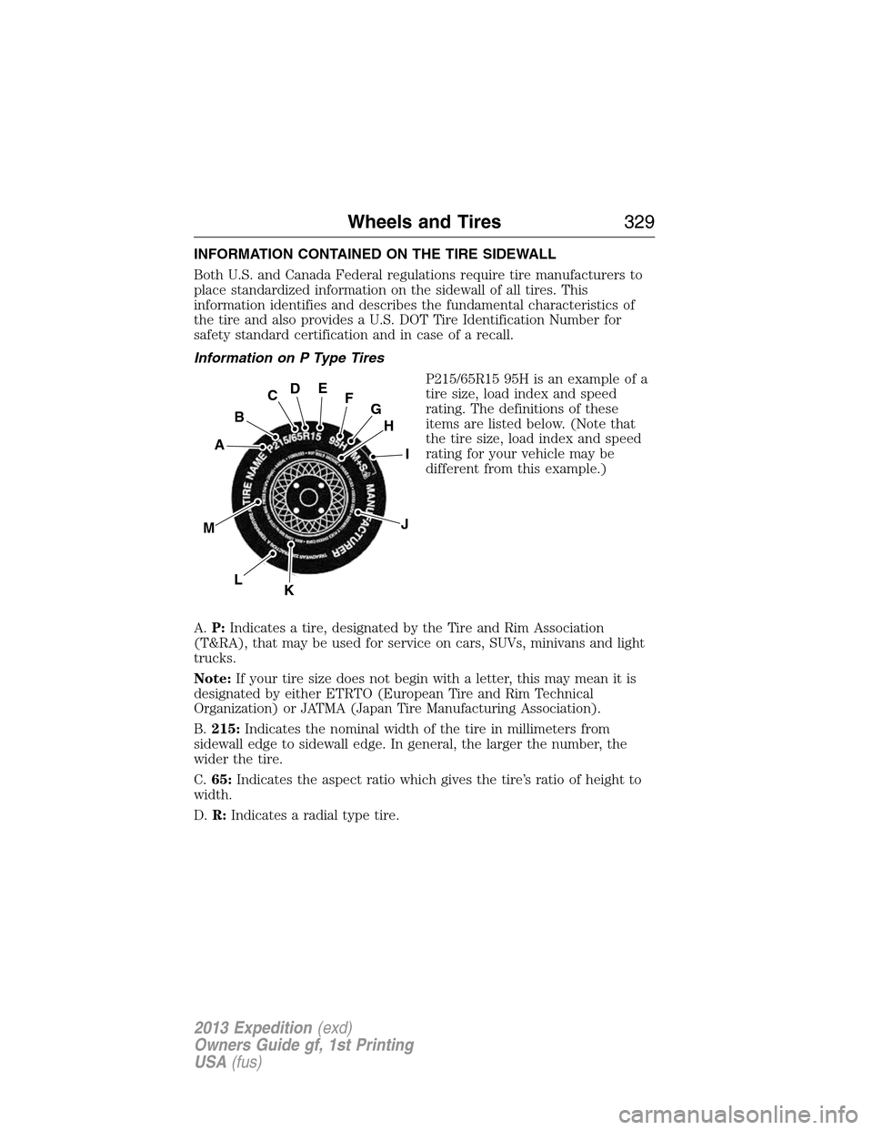
INFORMATION CONTAINED ON THE TIRE SIDEWALL
Both U.S. and Canada Federal regulations require tire manufacturers to
place standardized information on the sidewall of all tires. This
information identifies and describes the fundamental characteristics of
the tire and also provides a U.S. DOT Tire Identification Number for
safety standard certification and in case of a recall.
Information on P Type Tires
P215/65R15 95H is an example of a
tire size, load index and speed
rating. The definitions of these
items are listed below. (Note that
the tire size, load index and speed
rating for your vehicle may be
different from this example.)
A.P:Indicates a tire, designated by the Tire and Rim Association
(T&RA), that may be used for service on cars, SUVs, minivans and light
trucks.
Note:If your tire size does not begin with a letter, this may mean it is
designated by either ETRTO (European Tire and Rim Technical
Organization) or JATMA (Japan Tire Manufacturing Association).
B.215:Indicates the nominal width of the tire in millimeters from
sidewall edge to sidewall edge. In general, the larger the number, the
wider the tire.
C.65:Indicates the aspect ratio which gives the tire’s ratio of height to
width.
D.R:Indicates a radial type tire.
H
I
J
KL
M
A
B
CDEFG
Wheels and Tires329
2013 Expedition(exd)
Owners Guide gf, 1st Printing
USA(fus)
Page 333 of 497
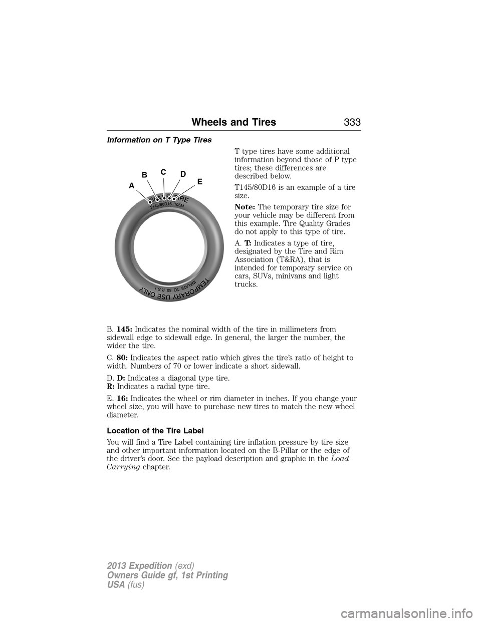
Information on T Type Tires
T type tires have some additional
information beyond those of P type
tires; these differences are
described below.
T145/80D16 is an example of a tire
size.
Note:The temporary tire size for
your vehicle may be different from
this example. Tire Quality Grades
do not apply to this type of tire.
A.T:Indicates a type of tire,
designated by the Tire and Rim
Association (T&RA), that is
intended for temporary service on
cars, SUVs, minivans and light
trucks.
B.145:Indicates the nominal width of the tire in millimeters from
sidewall edge to sidewall edge. In general, the larger the number, the
wider the tire.
C.80:Indicates the aspect ratio which gives the tire’s ratio of height to
width. Numbers of 70 or lower indicate a short sidewall.
D.D:Indicates a diagonal type tire.
R:Indicates a radial type tire.
E.16:Indicates the wheel or rim diameter in inches. If you change your
wheel size, you will have to purchase new tires to match the new wheel
diameter.
Location of the Tire Label
You will find a Tire Label containing tire inflation pressure by tire size
and other important information located on the B-Pillar or the edge of
the driver’s door. See the payload description and graphic in theLoad
Carryingchapter.
A
BCDE
Wheels and Tires333
2013 Expedition(exd)
Owners Guide gf, 1st Printing
USA(fus)
Page 336 of 497
Inspecting Your Tires and Wheel Valve Stems
Periodically inspect the tire treads for uneven or excessive wear and
remove objects such as stones, nails or glass that may be wedged in the
tread grooves. Check the tire and valve stems for holes, cracks, or cuts
that may permit air leakage and repair or replace the tire and replace
the valve stem. Inspect the tire sidewalls for cracking, cuts, bruises and
other signs of damage or excessive wear. If internal damage to the tire is
suspected, have the tire demounted and inspected in case it needs to be
repaired or replaced. For your safety, tires that are damaged or show
signs of excessive wear should not be used because they are more likely
to blow out or fail.
Improper or inadequate vehicle maintenance can cause tires to wear
abnormally. Inspect all your tires, including the spare, frequently, and
replace them if one or more of the following conditions exist:
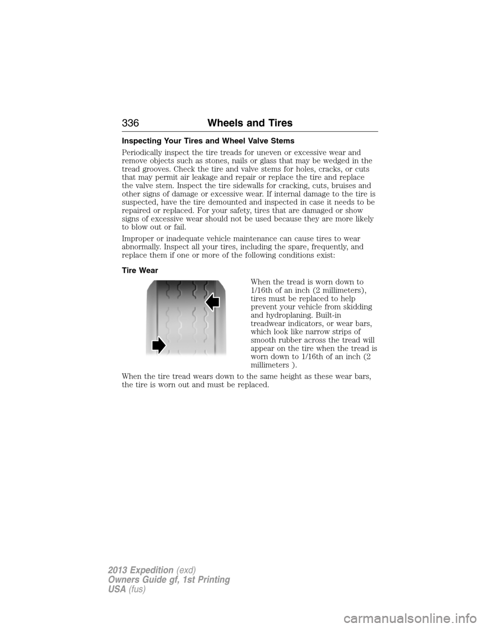
Tire Wear
When the tread is worn down to
1/16th of an inch (2 millimeters),
tires must be replaced to help
prevent your vehicle from skidding
and hydroplaning. Built-in
treadwear indicators, or wear bars,
which look like narrow strips of
smooth rubber across the tread will
appear on the tire when the tread is
worn down to 1/16th of an inch (2
millimeters ).
When the tire tread wears down to the same height as these wear bars,
the tire is worn out and must be replaced.
336Wheels and Tires
2013 Expedition(exd)
Owners Guide gf, 1st Printing
USA(fus)