2013 FORD B MAX instrument panel
[x] Cancel search: instrument panelPage 83 of 298

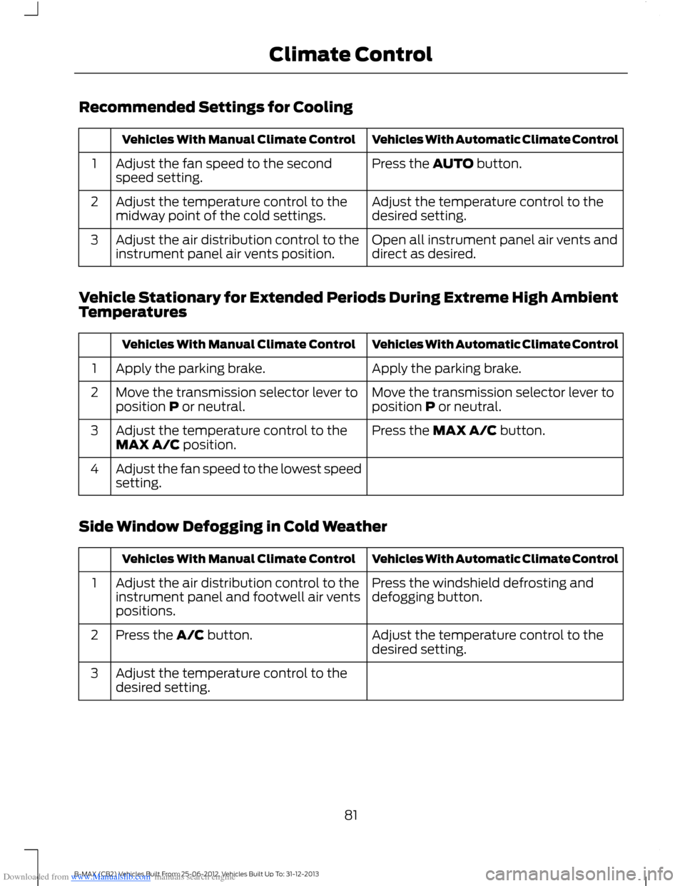
Downloaded from www.Manualslib.com manuals search engine Recommended Settings for Cooling
Vehicles With Automatic Climate ControlVehicles With Manual Climate Control
Press the AUTO button.Adjust the fan speed to the secondspeed setting.1
Adjust the temperature control to thedesired setting.Adjust the temperature control to themidway point of the cold settings.2
Open all instrument panel air vents anddirect as desired.Adjust the air distribution control to theinstrument panel air vents position.3
Vehicle Stationary for Extended Periods During Extreme High AmbientTemperatures
Vehicles With Automatic Climate ControlVehicles With Manual Climate Control
Apply the parking brake.Apply the parking brake.1
Move the transmission selector lever toposition P or neutral.Move the transmission selector lever toposition P or neutral.2
Press the MAX A/C button.Adjust the temperature control to theMAX A/C position.3
Adjust the fan speed to the lowest speedsetting.4
Side Window Defogging in Cold Weather
Vehicles With Automatic Climate ControlVehicles With Manual Climate Control
Press the windshield defrosting anddefogging button.Adjust the air distribution control to theinstrument panel and footwell air ventspositions.
1
Adjust the temperature control to thedesired setting.Press the A/C button.2
Adjust the temperature control to thedesired setting.3
81B-MAX (CB2) Vehicles Built From: 25-06-2012, Vehicles Built Up To: 31-12-2013Climate Control
Page 84 of 298

Downloaded from www.Manualslib.com manuals search engine Vehicles With Automatic Climate ControlVehicles With Manual Climate Control
Adjust the fan speed to the highestsetting.4
Direct the instrument panel side air ventstoward the side windows.5
Close the instrument panel vents.6
Maximum Cooling Performance inInstrument Panel or InstrumentPanel and Footwell Positions
1.Adjust the temperature control to thelowest setting.
2.Press the A/C and recirculated airbuttons.
3.Adjust the fan speed to the highestsetting initially and then adjust it to suitthe desired comfort level.
HEATED WINDOWS AND
MIRRORS
Heated Windows
Use the heated windows to defrost ordemist the windshield or rear window.
Note:The heated windows operate onlywhen the engine is running.
Heated Windshield
Heated Rear Window
Heated Exterior Mirrors
Electric exterior mirrors have a heatingelement that will defrost or demist themirror glass. They will switch onautomatically when you switch the heatedrear window on.
82B-MAX (CB2) Vehicles Built From: 25-06-2012, Vehicles Built Up To: 31-12-2013Climate Control
Page 93 of 298

Downloaded from www.Manualslib.com manuals search engine Note:A valid key must be located insideyour vehicle to switch the ignition on andstart the engine.
Ignition On
Press the button once. It is located on theinstrument panel near the steering wheel.All electrical circuits and accessories areoperational and the warning lamps andindicators will illuminate.
Starting With ManualTransmission
Note:Releasing the clutch pedal while theengine is starting will stop the enginecranking and return to ignition on.
1.Fully depress the clutch pedal.
2.Briefly press the button.
Starting With AutomaticTransmission
Note:Releasing the brake pedal while theengine is starting will stop the enginecranking and return to ignition on.
1.Move the transmission selector leverto position P or N.
2.Fully depress the brake pedal.
3.Briefly press the button.
Starting a Diesel Engine
Note:Engine cranking will not commenceuntil the engine glow plug indicator hasextinguished. This may take several secondsin extremely cold conditions.
Failure to Start
All Vehicles
The system will not function if:
•The key frequencies are jammed.
•The key battery has no charge.
If you are unable to start your vehicle, dothe following.
1.Hold the key next to the steeringcolumn exactly as shown.
2.With the key in this position you canuse the button to switch the ignition onand start your engine.
Manual Transmission
Note:Releasing the clutch pedal while theengine is starting will stop the enginecranking and return to ignition on. Amessage will be shown in the display.
If the engine does not crank when theclutch pedal has been fully depressed andthe button is pressed:
1.Fully depress both the clutch and brakepedals.
2.Press the button until the engine starts.
91B-MAX (CB2) Vehicles Built From: 25-06-2012, Vehicles Built Up To: 31-12-2013Starting and Stopping the Engine
Page 98 of 298

Downloaded from www.Manualslib.com manuals search engine AUTO-START-STOP
Note:For vehicles with start-stop thebattery requirement is different. It must bereplaced by one of exactly the samespecification as the original.
The system reduces fuel consumption andCO2 emissions by shutting down theengine when your vehicle is idling, forexample at traffic lights. The engine willautomatically restart when you press theclutch pedal or when required by a vehiclesystem, for example to recharge thebattery.
To obtain maximum benefit from thesystem, move the transmission selectorlever to neutral and release the clutchpedal during any stop of longer than threeseconds.
Using Start-Stop
WARNINGS
The engine may restartautomatically if required by thesystem.
Switch the ignition off beforeopening the hood or carrying out anymaintenance.
Always switch the ignition off beforeleaving your vehicle, as the systemmay have shut down the engine butthe ignition will still be live.
Note:The system only operates when theengine is warm and the outside temperatureis between 32°F (0°C) and 86°F (30°C).
Note:If you stall the engine, and thendepress the clutch pedal within a shortperiod of time, the system will automaticallyrestart the engine.
Note:The start-stop indicator willilluminate green when the engine shutsdown. See Warning Lamps and Indicators(page 58).
Note:When the start-stop indicator flashesamber, move the transmission selector leverto neutral or depress the clutch pedal.
Note:If the system detects a malfunction,it will switch off. Have your vehicle checkedby an authorized dealer.
Note:When you switch the system off, theswitch will illuminate.
Note:The system automatically turns onevery time you switch the ignition on. Toswitch the system off, press the switch inthe instrument panel. The system will onlybe switched off for the current ignition cycle.To turn it on, press the switch again. For itemlocation: See At a Glance (page 9).
To Stop the Engine
1.Stop your vehicle.
2.Move the transmission selector leverto neutral.
3.Release the clutch pedal.
4.Release the accelerator pedal.
The system may not shut down the engineunder certain conditions, for example:
•To maintain the interior climate.
•Low battery voltage.
•The outside temperature is too low ortoo high.
•The driver's door has been opened.
•Low engine operating temperature.
•Low brake system vacuum.
•If a road speed of 3 mph (5 km/h) hasnot been exceeded.
•The driver's safety belt has not beenfastened.
96B-MAX (CB2) Vehicles Built From: 25-06-2012, Vehicles Built Up To: 31-12-2013Unique Driving Characteristics
Page 117 of 298

Downloaded from www.Manualslib.com manuals search engine WARNINGS
Do not place objects in front of thecamera.
The camera is located on the liftgate nearthe handle.
Switching the Rear View CameraOn
WARNING
The camera may not detect objectsthat are close to your vehicle.
Switch the ignition and the audio unit on.
Press the parking aid switch in theinstrument panel or move the transmissionselector lever to position R (reverse).
The image is displayed on the screen.
The lamp in the switch illuminates whenthe system is switched on.
The camera may not operate correctly inthe following conditions:
•Dark areas.
•Intense light.
•If the ambient temperature increasesor decreases rapidly.
•If the camera is wet, for example in rainor high humidity.
•If the camera's view is obstructed, forexample by mud.
Using the Display
WARNINGS
Obstacles above the camera positionwill not be shown. Inspect the areabehind your vehicle if necessary.
Marks are for general guidance only,and are calculated for vehicles inmaximum load conditions on aneven road surface.
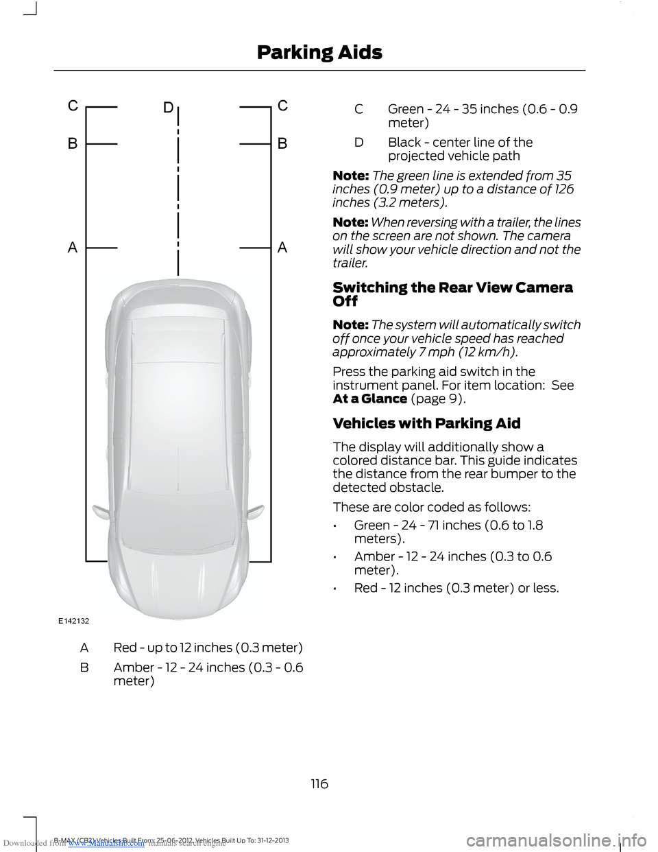
The lines show the distance from the outeredge of the front tire plus two inches (51millimeters) and the rear bumper.
115B-MAX (CB2) Vehicles Built From: 25-06-2012, Vehicles Built Up To: 31-12-2013Parking Aids
Page 118 of 298

Downloaded from www.Manualslib.com manuals search engine Red - up to 12 inches (0.3 meter)A
Amber - 12 - 24 inches (0.3 - 0.6meter)B
Green - 24 - 35 inches (0.6 - 0.9meter)C
Black - center line of theprojected vehicle pathD
Note:The green line is extended from 35inches (0.9 meter) up to a distance of 126inches (3.2 meters).
Note:When reversing with a trailer, the lineson the screen are not shown. The camerawill show your vehicle direction and not thetrailer.
Switching the Rear View CameraOff
Note:The system will automatically switchoff once your vehicle speed has reachedapproximately 7 mph (12 km/h).
Press the parking aid switch in theinstrument panel. For item location: SeeAt a Glance (page 9).
Vehicles with Parking Aid
The display will additionally show acolored distance bar. This guide indicatesthe distance from the rear bumper to thedetected obstacle.
These are color coded as follows:
•Green - 24 - 71 inches (0.6 to 1.8meters).
•Amber - 12 - 24 inches (0.3 to 0.6meter).
•Red - 12 inches (0.3 meter) or less.
116B-MAX (CB2) Vehicles Built From: 25-06-2012, Vehicles Built Up To: 31-12-2013Parking Aids
Page 134 of 298

Downloaded from www.Manualslib.com manuals search engine HAZARD WARNING FLASHERS
The hazard warning button is located onthe instrument panel. Use it when yourvehicle is creating a safety hazard for othermotorists.
Press the button to turn on the hazardwarning function, and the front and reardirection indicators will flash.
Press the button again to turn them off.
Note:If used when the engine is notrunning, the battery will lose charge. Theremay be insufficient power to restart yourengine.
Note:Depending on applicable laws andregulations in the country for which yourvehicle was originally built, the hazardwarning flashers may flash if you brakeheavily.
FIRST AID KIT
Space is provided in the luggagecompartment.
WARNING TRIANGLE
Space is provided in the luggagecompartment.
JUMP-STARTING THE VEHICLE
WARNINGS
Do not use fuel lines, engine rockercovers or the intake manifold asgrounding points.
Connect batteries with only the samenominal voltage.
WARNINGS
Always use booster cables withinsulated clamps and adequate sizecable.
Note:Do not disconnect the battery fromyour vehicle’s electrical system.
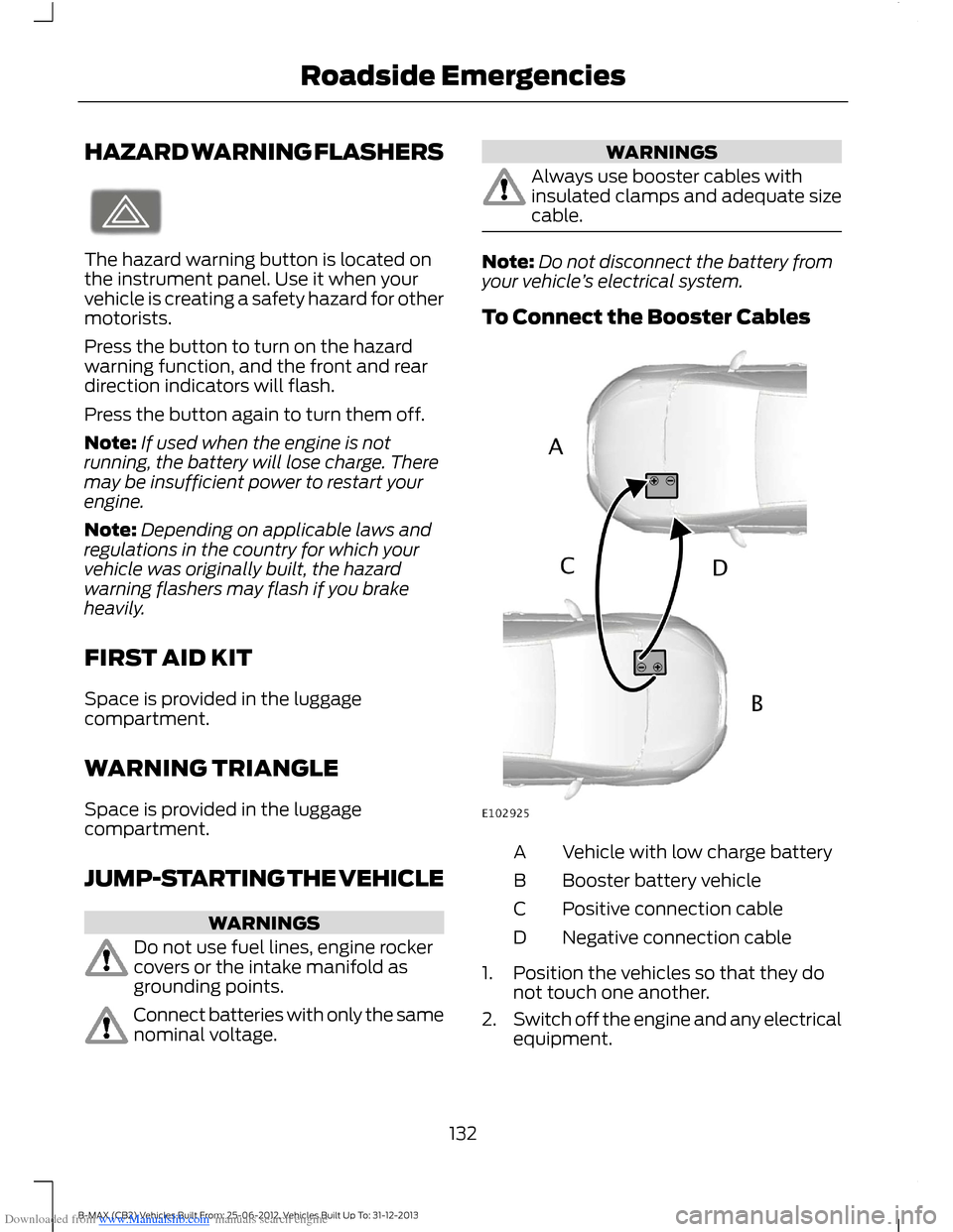
To Connect the Booster Cables
Vehicle with low charge batteryA
Booster battery vehicleB
Positive connection cableC
Negative connection cableD
1.Position the vehicles so that they donot touch one another.
2.Switch off the engine and any electricalequipment.
132B-MAX (CB2) Vehicles Built From: 25-06-2012, Vehicles Built Up To: 31-12-2013Roadside Emergencies
Page 141 of 298

Downloaded from www.Manualslib.com manuals search engine Circuits protectedFuse ratingFuse
Ignition, electric powerassisted steering, instrumentcluster, passive anti-theftsystem, anti-lock brakingsystem
10 A13
Powertrain control module,transmission selector lever,fuel pump7.5 A14
Audio system, instrumentcluster7.5 A15
Heated windshield7.5 A16
Not used-17
Not used-18
Data link connector15 A19
Multi function display, clock,internal scanner, heatingvents, air conditioning panel20 A20
Audio system, navigation,bluetooth15 A21
Instrument cluster7.5 A22
Trailer module7.5 A23
Sync module antenna7.5 A24
Not used-25
Front wiper, left-hand side30 A26
Front wiper, right-hand side30 A27
Circuits switchedRelay
IgnitionR1
139B-MAX (CB2) Vehicles Built From: 25-06-2012, Vehicles Built Up To: 31-12-2013Fuses