Page 121 of 298

Downloaded from www.Manualslib.com manuals search engine ACTIVE CITY STOP
General Information
WARNINGS
The system does not relieve you ofyour responsibility to drive with duecare and attention.
At all times you are responsible forcontrolling your vehicle, supervisingthe system and intervening ifrequired.
Never look directly into the sensorwith any type of object. There is a riskof eye injury.
If the sensor becomes blocked thesystem may not function.
To achieve full system performance,you must bed the braking system in.See Breaking-In (page 130).
The system performance may varydepending on your vehicle and roadconditions.
The system will not react to vehiclesdriving in a different direction.
The system will not react to bicycles,motorcycles, people or animals.
When the ignition is on the sensorwill constantly transmit a laserbeam.
The system will not operate duringharsh acceleration and steering.
In cold and severe weatherconditions the system may notfunction. Rain, snow, spray and icecan all influence the sensor.
Do not carry out windshield repairsin the immediate area surroundingthe sensor.
WARNINGS
If you install a windshield notapproved by us, the system may notfunction correctly.
If the engine stops after the systemhas been switched on, the hazardwarning flashers will turn on.
The system may not function whendriving around sharp curves.
Note:Keep the windshield free fromobstructions such as bird droppings, insects,snow or ice.
Note:Keep the hood free of ice and snow,otherwise the system may not functioncorrectly.
A sensor is mounted behind the interiorrear view mirror. It continuously monitorsconditions to decide when to intervene.
The system is designed to help you reducelow speed collisions into the rear ofanother vehicle. It will also help you reducethe impact damage or potentially avoidthe collision completely.
The system operates at speeds belowapproximately 19 mph (30 km/h) byapplying the brakes when the sensordetects that a collision is likely.
You must depress the brake pedal toobtain full braking force.
When the system is braking or hasautomatically applied the brakes, amessage will be shown in the informationdisplay.
Using Active City Stop
Switching the System Off and On
Note:The system automatically turns onevery time you switch the ignition on.
119B-MAX (CB2) Vehicles Built From: 25-06-2012, Vehicles Built Up To: 31-12-2013Driving Aids
Page 122 of 298

Downloaded from www.Manualslib.com manuals search engine In certain situations it is advisable todisable the system, for example:
•Driving off road when objects maycover the windshield.
•Driving through a car wash facility.
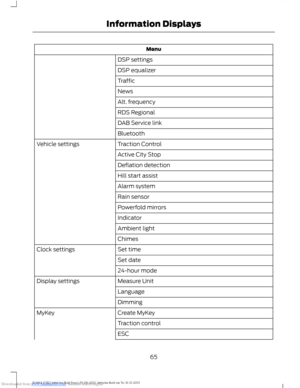
You can switch the system off and on usingthe information display. See GeneralInformation (page 63).
Active City Stop Relearning Procedure
Note:When you disconnect the battery, thesystem will go through a relearningprocedure. During this time the system willnot be available.
You must drive your vehicle above 31mph(50 km/h) in a straight line for theprocedure to complete. This proceduremay take several minutes.
Laser Sensor Information
WARNINGS
Invisible laser radiation. Do not viewdirectly with optical instruments(magnifiers). Class 1M laser product.
IEC 60825-1: 1993 + A2:2001.Complies with FDA performancestandards for laser products exceptfor deviation pursuant to Laser Notice No.50, dated July 26th, 2001.
SpecificationItem
45mWMax average power
33nsPulse duration
905nmWavelength
120B-MAX (CB2) Vehicles Built From: 25-06-2012, Vehicles Built Up To: 31-12-2013Driving Aids
Page 123 of 298

Downloaded from www.Manualslib.com manuals search engine GENERAL INFORMATION
WARNINGS
Use load securing straps to anapproved standard, e.g. DIN.
Make sure that you secure all looseitems properly.
Place luggage and other loads as lowand as far forward as possible withinthe luggage or loadspace.
Do not drive with the liftgate or reardoor open. Exhaust fumes may enteryour vehicle.
Do not exceed the maximum frontand rear axle loads for your vehicle.See Vehicle Identification Plate(page 186).
Do not allow items to contact therear windows.
Note:When loading long objects in to yourvehicle, for example pipes, timber orfurniture be careful not to damage theinterior trim.
LUGGAGE ANCHOR POINTS
REAR UNDER FLOOR
STORAGE
Adjustable Load Floor
Vehicles with the standard size spare tirecan adjust the load floor to two positions.The load floor can be placed on either thehigh or the low position on shelves locatedat the rear of the luggage compartmenttrim.
121B-MAX (CB2) Vehicles Built From: 25-06-2012, Vehicles Built Up To: 31-12-2013Load Carrying
Page 124 of 298
Downloaded from www.Manualslib.com manuals search engine CARGO NETS
Installing and Removing the Net
Installing the Net
1.Raise the rear outer head restraints.See Head Restraints (page 83).
2.Attach the top securing clips to thehead restraint guides.
3.Attach the bottom securing clips to thebottom anchor points.
Removing the Net
1.Raise the rear outer head restraints.See Head Restraints (page 83).
2.Remove the top and bottom securingclips.
LUGGAGE COVERS
WARNING
Do not place objects on the luggagecover.
Removing the Cover
DOG GUARD
WARNING
Keep a small distance between thedog guard and the rear seats.
1.Attach the dog guard to the upper andlower anchor points. Tighten thehandwheels.
122B-MAX (CB2) Vehicles Built From: 25-06-2012, Vehicles Built Up To: 31-12-2013Load Carrying
Page 125 of 298
Downloaded from www.Manualslib.com manuals search engine 123B-MAX (CB2) Vehicles Built From: 25-06-2012, Vehicles Built Up To: 31-12-2013Load Carrying
Page 126 of 298

Downloaded from www.Manualslib.com manuals search engine TOWING A TRAILER
WARNINGS
Do not exceed 62 mph (100 km/h).This could result in the loss of vehiclecontrol, serious personal injury ordeath.
The rear tire pressures must beincreased by 3 psi (0.2 bar) abovespecification. Do not exceed themaximum pressure stated on the tiresidewall. This could cause serious personalinjury. See Wheels and Tires (page 174).
Do not exceed the maximum grosstrain weight stated on your vehicleidentification plate. This could resultin the loss of vehicle control, seriouspersonal injury or death. See VehicleIdentification Plate (page 186).
Do not exceed the maximumpermissible trailer nose weight(vertical weight on the tow ball) asstated in the vehicle specification chart.This could result in the loss of vehiclecontrol, serious personal injury or death.See Capacities and Specifications(page 186).
The anti-lock braking system doesnot control the overrun brake on thetrailer. This could result in the loss ofvehicle control, serious personal injury ordeath.
When towing a trailer:
•Obey country specific regulations fortowing a trailer.
•Do not exceed 62 mph (100 km/h)even if a country allows higher speedsunder certain conditions.
•Place loads as low as possible andcentral to the axle of your trailer. If youare towing with an unladen vehicle, theload in your trailer should be placedtoward the nose, within the maximumnose load, as this gives the beststability. See Capacities andSpecifications (page 186).
•The trailer nose weight (vertical weighton the tow ball), is essential for thedriving stability of your vehicle andtrailer.
•The vertical weight on the tow ballshould be at least 4% of the trailerweight and not exceed the maximumpermissable weight. See Capacitiesand Specifications (page 186).
•Reduce speed immediately if the trailershows any sign of swaying.
•Use a low gear when descending asteep downhill gradient.
Note:The maximum permissible trailernose weight on the trailer identificationplate is the trailer manufacturer’s testingvalue. The vehicle maximum permissibletrailer nose weight may be lower.
The stability of your vehicle to trailercombination is very much dependent onthe quality of the trailer.
Towing a trailer changes the vehiclehandling characteristics and increasesstopping distances. Adapt your speed anddriving behavior to the load of the trailer.
The gross train weight stated on thevehicle identification plate applies for roadgradients up to 12% and altitudes up to3281 feet (1000 meters) when towing atrailer. In mountainous regions the engineperformance decreases due to lower airdensity with increasing altitude. In highaltitude regions above 3281feet (1000metres), the stipulated maximumpermitted gross train weight must bereduced by 10% for every extra 3281 feet(1000 metres).
124B-MAX (CB2) Vehicles Built From: 25-06-2012, Vehicles Built Up To: 31-12-2013Towing
Page 127 of 298

Downloaded from www.Manualslib.com manuals search engine Note:Not all vehicles are suitable orapproved to have tow bars fitted. See anauthorized dealer for further information.
Trailer Lighting
The electrical system on your vehicle is notsuitable for towing trailers with LED lamps.
TOW BALL
WARNINGS
When not in use, always transportthe tow ball arm securely fastenedin the luggage compartment.
Take special care when fitting thetow ball arm as the safety of yourvehicle and the trailer depends onthis.
Do not use any tools for mounting ordismounting the tow ball arm.
Do not modify the trailer coupling.
Do not disassemble or repair the towball arm.
A 13-pin trailer socket and the tow ball armseat are provided under the rear bumper.Turn the trailer socket down through 90degrees until it engages in the end position.
Unlocking the Tow Ball ArmMechanism
1.Remove the protecting cap.
2.Insert the key and turn it clockwise tounlock.
3.Hold the tow ball arm. Pull thehandwheel out and turn it clockwiseuntil it clicks.
Note:The red mark on the handwheel mustalign with the green mark on the tow ball.
4.Release the handwheel. The tow ballarm is unlocked.
Inserting the Tow Ball Arm
WARNING
The tow ball arm may only beinserted when completely unlocked.
125B-MAX (CB2) Vehicles Built From: 25-06-2012, Vehicles Built Up To: 31-12-2013Towing
Page 128 of 298
Downloaded from www.Manualslib.com manuals search engine Note:Pull out the plug.
1.Insert the tow ball arm vertically andpress it upwards until it engages.
Note:Do not hold your hand near thehandwheel.
Note:The green mark on the handwheelmust align with the green mark on the towball.
2.Turn the key counterclockwise andremove the key to lock the tow ball.
3.Pull the protecting cap from the keybow and press it onto the lock.
Driving With a Trailer
WARNING
If any of the below conditions cannotbe met, do not use the tow bar andhave it checked by an authorizeddealer.
Before starting your journey, make surethat the tow ball arm is correctly locked.Check that:
•the green marks are aligned
•the handwheel (A) is correctly fitted tothe tow ball arm
•you have removed the key (B)
•the tow ball arm is securely positioned.
Removing the Tow Ball Arm
126B-MAX (CB2) Vehicles Built From: 25-06-2012, Vehicles Built Up To: 31-12-2013Towing