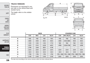
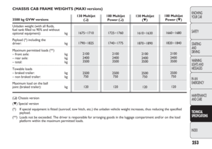
Page 81 of 287

77
KNOWING
YOUR CAR
SAFETY
STARTING
AND
DRIVING
WARNING
LIGHTS AND
MESSAGES
IN AN
EMERGENCY
MAINTENANCE
AND CARE
TECHNICAL
SPECIFICATIONS
INDEX
❒when opening one of the side doors for about
3 minutes;
❒when one of the doors is closed for a period of
about 10 seconds.
The timed delay period ends automatically when the
doors are locked.
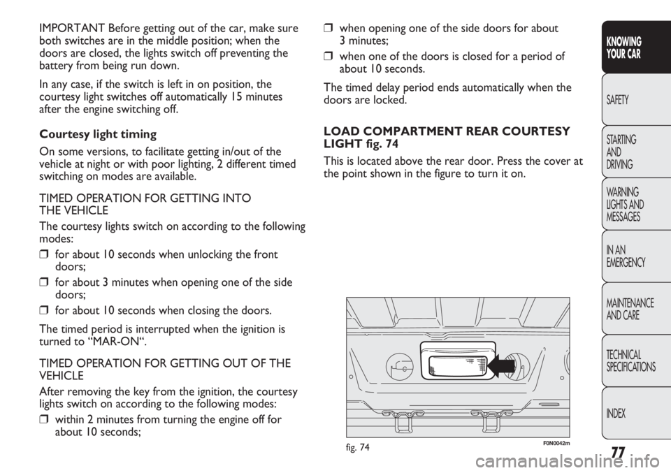
LOAD COMPARTMENT REAR COURTESY
LIGHT fig. 74
This is located above the rear door. Press the cover at
the point shown in the figure to turn it on. IMPORTANT Before getting out of the car, make sure
both switches are in the middle position; when the
doors are closed, the lights switch off preventing the
battery from being run down.
In any case, if the switch is left in on position, the
courtesy light switches off automatically 15 minutes
after the engine switching off.
Courtesy light timing
On some versions, to facilitate getting in/out of the
vehicle at night or with poor lighting, 2 different timed
switching on modes are available.
TIMED OPERATION FOR GETTING INTO
THE VEHICLE
The courtesy lights switch on according to the following
modes:
❒for about 10 seconds when unlocking the front
doors;
❒for about 3 minutes when opening one of the side
doors;
❒for about 10 seconds when closing the doors.
The timed period is interrupted when the ignition is
turned to “MAR-ON“.
TIMED OPERATION FOR GETTING OUT OF THE
VEHICLE
After removing the key from the ignition, the courtesy
lights switch on according to the following modes:
❒within 2 minutes from turning the engine off for
about 10 seconds;
F0N0042mfig. 74
Page 82 of 287
78
KNOWING
YOUR CAR
SAFETY
STARTING
AND
DRIVING
WARNING
LIGHTS AND
MESSAGES
IN AN
EMERGENCY
MAINTENANCE
AND CARE
TECHNICAL
SPECIFICATIONS
INDEX
F0N0220mfig. 76F0N0219mfig. 75
REMOVABLE COURTESY LIGHT fig. 76
(for versions/markets where provided)
It is used as both a fixed light and a portable electric
torch. When the removable light is secured to its fixed
support, the electric torch battery is automatically
recharged. The courtesy light is recharged with the
vehicle stationary and the ignition key either in the
STOP position (OFF) or extracted for a limit of
15 minutes. LOAD COMPARTMENT SIDE COURTESY
LIGHT fig. 75
(for versions/markets where provided)
Press the cover at the point shown in the figure to turn
it on.
Page 83 of 287

79
KNOWING
YOUR CAR
SAFETY
STARTING
AND
DRIVING
WARNING
LIGHTS AND
MESSAGES
IN AN
EMERGENCY
MAINTENANCE
AND CARE
TECHNICAL
SPECIFICATIONS
INDEX
F0N0044mfig. 77F0N0045mfig. 78
The function switches off automatically when emergency
braking ceases.
This function complies with the relevant legislations
currently in force.
FOG LIGHTS fig. 78
(for versions/markets where provided)
To turn the front fog lights on, press the button
5with
the side lights on.
The warning light 5in the instrument panel will come on.
Press the button again to turn the lights off.
The use of fog lights is governed by the highway code of
the country you are in. Comply with legal requirements.
CONTROLS
HAZARD WARNING LIGHTS fig. 77
They are turned on by pressing switch A, regardless of
the position of the ignition key.
With the device on, warning lights
Îand ¥light up in
the instrument panel.
Press the switch again to turn the lights off.
The use of hazard lights is governed by the Highway
Code of the country you are in. Comply with legal
requirements.
Emergency braking
During emergency braking, the hazard warning lights
come on automatically and warning lights
Îand ¥in
the panel come on at the same time.
Page 84 of 287

80
KNOWING
YOUR CAR
SAFETY
STARTING
AND
DRIVING
WARNING
LIGHTS AND
MESSAGES
IN AN
EMERGENCY
MAINTENANCE
AND CARE
TECHNICAL
SPECIFICATIONS
INDEX
F0N0046mfig. 79
F0N0043mfig. 80
PARKING LIGHTS
These lights can only be turned on with ignition key in
the STOP position or removed, by turning the control
on the left lever first to
Oand then to position 6or
2. The warning light 3on the instrument panel
comes on.
HEATED REAR WINDSCREEN fig. 80
(for versions/markets where provided)
Press button A to turn this function on. It will turn off
automatically after about 20 minutes.
BATTERY DISCONNECTION FUNCTION
(DISCONNECT SWITCH)
(for versions/markets where provided)
The battery disconnection function is enabled with the
ignition key in the BATT position, as illustrated on the
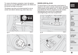
dedicated plate located in the area illustrated in fig. 81.
To turn the ignition key to the BATT position, press the
button A (red) fig. 82. The battery will be disconnected,
by interrupting the earth lead, about 45 seconds after
the key is turned to the BATT position.
This 45 second period is necessary to:
❒allow the driver to get out of the vehicle and lock
the doors using the remote control;
❒guarantee that all the vehicle electrical systems have
been deactivated.
With the battery disconnected, access to the vehicle will
only be possible by unlocking the driver’s door using the
mechanical lock. REAR FOG LAMPS fig. 79
These lights come on, with the dipped headlights on or
with the side lights and fog lights on (for versions/markets
where provided) by pressing the button 4. The warning
light 4in the instrument panel will come on. Press the
button again to turn the lights off, or turn off the dipped
beams and/or the front fog lights (where provided). The
use of rear fog lamps is governed by the Highway Code of
the country you are in. Comply with legal requirements.
Page 85 of 287
81
KNOWING
YOUR CAR
SAFETY
STARTING
AND
DRIVING
WARNING
LIGHTS AND
MESSAGES
IN AN
EMERGENCY
MAINTENANCE
AND CARE
TECHNICAL
SPECIFICATIONS
INDEX
F0N0811mfig. 81
F0N0810mfig. 82F0N0132mfig. 84
F0N0047mfig. 83
DOOR LOCK fig. 83-84
To lock all doors at the same time, press button A,
located on the centre console control panel, regardless
of the position of the ignition key. To unlock the doors,
press button B. There is a button D on the window
opening panel that controls the independent
unlocking/locking of the load compartment. To restore the battery connection, insert the ignition
key and turn it to the MAR-ON position, the vehicle can
be started normally at this point.
The battery may have to be disconnected to set up
certain new electric devices (e.g. clock, date, etc.).
Page 86 of 287

82
KNOWING
YOUR CAR
SAFETY
STARTING
AND
DRIVING
WARNING
LIGHTS AND
MESSAGES
IN AN
EMERGENCY
MAINTENANCE
AND CARE
TECHNICAL
SPECIFICATIONS
INDEX
F0N0048mfig. 85
ELECTRICAL POWER SUPPLY AND
FUEL CUT OFF SWITCH
The vehicle is fitted with a safety switch that, in the
event of a crash, comes into operation by cutting off the
fuel supply and turning off the engine as a consequence.
When the inertia switch cuts in, this cuts off the fuel
supply and also activates the hazard warning lights, side
lights and courtesy lights while releasing all the doors
and displaying a message; they are deactivated by
pressing button A. An additional safety switch is also
present that is activated in the event of impact to cut off
the electrical supply. In this way, fuel is prevented from
escaping if the pipes are broken as well as the formation
of sparks or electrical discharges following damage to
the vehicle electrical components.
IMPORTANT After an accident, remember to remove
the key from the ignition device to avoid draining the
battery.
If no fuel leaks or damage to vehicle electrical
devices (e.g. headlights) are detected after the impact and the
vehicle is able to set off again, reactivate the automatic fuel
cut off and electrical supply switches (
for versions/markets
where provided)
following the procedure described below.
If, after a crash, you smell fuel or see
leaks from the fuel system, do not reset
the switches to avoid the risk of fire.
WARNING
Reactivating the fuel cut-off switch fig. 85
Press the button A to reactivate the fuel cut off switch.
Page 87 of 287
83
KNOWING
YOUR CAR
SAFETY
STARTING
AND
DRIVING
WARNING
LIGHTS AND
MESSAGES
IN AN
EMERGENCY
MAINTENANCE
AND CARE
TECHNICAL
SPECIFICATIONS
INDEX
F0N0127mfig. 86
IMPORTANT On versions other than the School
bus/Minibus, button B is replaced by a dedicated fuse;
to replace it contact a Fiat Dealership.
Before reactivating the electricity supply
switch, carefully check for fuel leaks
or damage to the vehicle electrical devices
(e.g. headlights).
WARNING
Before reactivating the fuel cut off
switch, carefully check for fuel leaks
or damage to vehicle electrical devices
(e.g. headlights).
WARNING
Reactivating the electrical supply cut-off switch
(School bus/Minibus) fig. 86
The switch is located on the positive battery terminal.
To reactivate the electrical supply switch, proceed as
follows:
❒press the button A to reset the fuel cut off switch;
❒press button B to reset the electrical supply switch.
Page 88 of 287
84
KNOWING
YOUR CAR
SAFETY
STARTING
AND
DRIVING
WARNING
LIGHTS AND
MESSAGES
IN AN
EMERGENCY
MAINTENANCE
AND CARE
TECHNICAL
SPECIFICATIONS
INDEX
F0N0049mfig. 87
INTERIOR FITTINGS
UPPER GLOVE COMPARTMENT
– REFRIGERATED COMPARTMENT fig.87
(for versions/markets where provided)
To use, lift the flap as shown in the figure.
If air conditioned, the compartment, equipped with
a bottle holder, may be cooled/heated by means of an
outlet connected to the climate control system.GLOVE COMPARTMENT fig. 88
To open the glove compartment, operate the opening
handle A.
F0N0050mfig. 88