Page 101 of 599
Periodic Safety Checks You Should Make Outside
The Vehicle
Tires
Examine tires for excessive tread wear and uneven wear
patterns. Check for stones, nails, glass, or other objects
lodged in the tread or sidewall. Inspect the tread for cuts
and cracks. Inspect sidewalls for cuts, cracks and bulges.
Check the wheel nuts for tightness. Check the tires
(including spare) for proper cold inflation pressure.
Lights
Have someone observe the operation of brake lights and
exterior lights while you work the controls. Check turn
signal and high beam indicator lights on the instrument
panel.
Door Latches
Check for positive closing, latching, and locking.
Fluid Leaks
Check area under vehicle after overnight parking for fuel,
engine coolant, oil, or other fluid leaks. Also, if gasoline
fumes are detected or if fuel, power steering fluid, or
brake fluid leaks are suspected, the cause should be
located and corrected immediately.
2
THINGS TO KNOW BEFORE STARTING YOUR VEHICLE 99
Page 241 of 599

NOTE:
•The vehicle should be traveling at a steady speed and
on level ground before pressing the SET button.
• The Electronic Speed Control may not engage if a
different size tire is installed on one wheel, such as the
compact spare tire (if equipped).
To Deactivate
A soft tap on the brake pedal, pushing the CANCEL
button, or normal brake pressure while slowing the
vehicle will deactivate Electronic Speed Control without
erasing the set speed memory. Pressing the ON/OFF
button or turning the ignition switch OFF erases the set
speed memory.
To Resume Speed
To resume a previously set speed, push the RES (+)
button and release. Resume can be used at any speed
above 20 mph (32 km/h).
To Vary The Speed Setting
When the Electronic Speed Control is set, you can in-
crease speed by pushing the RES (+) button. If the button
is continually pressed, the set speed will continue to
increase until the button is released, then the new set
speed will be established.
Pressing the RES (+) button once will result ina1mph
(1.6 km/h) increase in set speed. Each subsequent tap of
the button results in an increase of 1 mph (1.6 km/h).
3
UNDERSTANDING THE FEATURES OF YOUR VEHICLE 239
Page 314 of 599

odometer needs to be repaired or serviced, the repair
technician should leave the odometer reading the same
as it was before the repair or service. If s/he cannot do so,
then the odometer must be set at zero, and a sticker must
be placed in the door jamb stating what the mileage was
before the repair or service. It is a good idea for you to
make a record of the odometer reading before the repair/
service, so that you can be sure that it is properly reset, or
that the door jamb sticker is accurate if the odometer
must be reset at zero.
Electronic Vehicle Information Center (EVIC) Display
The Electronic Vehicle Information Center (EVIC) fea-
tures a driver-interactive display that is located in the
instrument cluster. For further information, refer to
“Electronic Vehicle Information Center (EVIC)”.
The Shift Lever Indicator is self-contained within the
EVIC display. It displays the gear position of the auto-
matic transmission.NOTE:
•
You must apply the brakes before shifting from PARK.
•The highest available transmission gear is displayed
in the lower right corner of the Electronic Vehicle
Information Center (EVIC) whenever the Electronic
Range Select (ERS) feature is active. Use the +/-
selector on the shift lever to activate ERS. Refer to
“Automatic Transmission” in “Starting And Operat-
ing” for further information.
7. Tire Pressure Monitoring Telltale Light — If Equipped
Each tire, including the spare (if provided),
should be checked monthly when cold and in-
flated to the inflation pressure recommended by
the vehicle manufacturer on the vehicle placard
or tire inflation pressure label. (If your vehicle has tires of
312 UNDERSTANDING YOUR INSTRUMENT PANEL
Page 338 of 599

Press and release the UP or DOWN button until “Vehicle
Info” displays in the EVIC and press the SELECT button.
Press the UP and DOWN button to scroll t")
Vehicle Info (Customer Information Features)
Press and release the UP or DOWN button until “Vehicle
Info” displays in the EVIC and press the SELECT button.
Press the UP and DOWN button to scroll through the
available information displays, then press SELECT to
display any one of the following choices.
•Coolant Temp
Displays the actual coolant temperature.
• Oil Temperature
Displays the actual oil temperature.
• Oil Pressure
Displays the actual oil pressure.
• Trans Temperature
Displays the actual transmission temperature. •
Engine Hours
Displays the number of hours of engine operation.
• Tire Pressure
Shows the actual tire pressure for each tire (EXCLUDING
THE SPARE TIRE).
Messages #
Select from Main Menu using the UP or DOWN buttons.
This feature shows the number of stored warning mes-
sages (in the # place holder). Pressing the SELECT button
will allow you to see what the stored messages are.
Pressing the BACK button takes you back to the Main
Menu.
336 UNDERSTANDING YOUR INSTRUMENT PANEL
Page 391 of 599

▫Tire Inflation Pressures .................439
▫ Tire Pressures For High Speed Operation . . . .440
▫ Radial Ply Tires ..................... .441
▫ Tire Types .......................... .442
▫ Run Flat Tires ....................... .443
▫ Spare Tires ......................... .443
▫ Tire Spinning ....................... .446
▫ Tread Wear Indicators ..................446
▫ Life Of Tire ........................ .447
▫ Replacement Tires .....................447
� TIRE CHAINS ........................ .449
� TIRE ROTATION RECOMMENDATIONS .....450
▫ Tire Rotation ........................ .451�TIRE PRESSURE MONITOR SYSTEM (TPMS) . . .451
▫
Premium System ..................... .454
▫ General Information ...................457
� FUEL REQUIREMENTS ..................458
▫ 6.4L Engine ......................... .458
▫ Reformulated Gasoline .................458
▫ Gasoline/Oxygenate Blends ..............459
▫ E-85 Usage In Non-Flex Fuel Vehicles .......459
▫ MMT In Gasoline .....................460
▫ Materials Added To Fuel ................460
▫ Fuel System Cautions ...................461
▫ Carbon Monoxide Warnings .............462
5
STARTING AND OPERATING 389
Page 430 of 599
 - Metric tire sizing is based on U.S.
design standards. P-Metric tires have the letter “P”
molded into the sidewall preceding the size designa-
tion. Example: P215/65R15 95H")
NOTE:
•P (Passenger) - Metric tire sizing is based on U.S.
design standards. P-Metric tires have the letter “P”
molded into the sidewall preceding the size designa-
tion. Example: P215/65R15 95H.
• European-Metric tire sizing is based on European
design standards. Tires designed to this standard have
the tire size molded into the sidewall beginning with
the section width. The letter �P�is absent from this tire
size designation. Example: 215/65R15 96H. •
LT (Light Truck) - Metric tire sizing is based on U.S.
design standards. The size designation for LT-Metric
tires is the same as for P-Metric tires except for the
letters “LT” that are molded into the sidewall preced-
ing the size designation. Example: LT235/85R16.
• Temporary spare tires are spares designed for tempo-
rary emergency use only. Temporary high pressure
compact spare tires have the letter “T” or “S” molded
into the sidewall preceding the size designation. Ex-
ample: T145/80D18 103M.
• High flotation tire sizing is based on U.S. design
standards and it begins with the tire diameter molded
into the sidewall. Example: 31x10.5 R15 LT.
428 STARTING AND OPERATING
Page 431 of 599
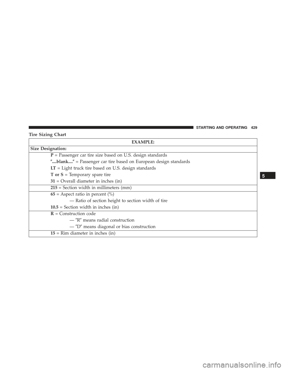
Tire Sizing Chart
EXAMPLE:
Size Designation: P= Passenger car tire size based on U.S. design standards
�....blank....� = Passenger car tire based on European design standards
LT = Light truck tire based on U.S. design standards
TorS= Temporary spare tire
31 = Overall diameter in inches (in)
215 = Section width in millimeters (mm)
65 = Aspect ratio in percent (%)
— Ratio of section height to section width of tire
10.5 = Section width in inches (in)
R = Construction code
—�R� means radial construction
— �D� means diagonal or bias construction
15 = Rim diameter in inches (in)
5
STARTING AND OPERATING 429
Page 437 of 599
 tire size designed for your vehicle
4) cold tire inflation pressures for the front, rear, and
spare tires.
Loading
The vehicle maximum load on the tire must not exceed
the load carrying capacity of")
3) tire size designed for your vehicle
4) cold tire inflation pressures for the front, rear, and
spare tires.
Loading
The vehicle maximum load on the tire must not exceed
the load carrying capacity of the tire on your vehicle. You
will not exceed the tire’s load carrying capacity if you
adhere to the loading conditions, tire size, and cold tire
inflation pressures specified on the Tire and Loading
Information placard and in the “Vehicle Loading” section
of this manual.
NOTE:Under a maximum loaded vehicle condition,
gross axle weight ratings (GAWRs) for the front and rear
axles must not be exceeded. For further information on
GAWRs, vehicle loading, and trailer towing, refer to
“Vehicle Loading” in this section. To determine the maximum loading conditions of your
vehicle, locate the statement “The combined weight of
occupants and cargo should never exceed XXX lbs or
XXX kg” on the Tire and Loading Information placard.
The combined weight of occupants, cargo/luggage and
trailer tongue weight (if applicable) should never exceed
the weight referenced here.
Steps For Determining Correct Load Limit
1. Locate the statement “The combined weight of occu-
pants and cargo should never exceed XXX lbs or
XXX kg” on your vehicle’s placard.
2. Determine the combined weight of the driver and passengers that will be riding in your vehicle.
3. Subtract the combined weight of the driver and pas- sengers from XXX lbs or XXX kg.
5
STARTING AND OPERATING 435