2013 BMW X6M brake
[x] Cancel search: brakePage 67 of 327

Automatic Hold is deactivated.
If the vehicle is being held by Automatic Hold,
then press on the brake pedal to deactivate it.
When the parking brake is set manually, refer
to page 61, Automatic Hold is deactivated au‐
tomatically.
Driving Automatic Hold is activated: the vehicle is au‐
tomatically secured against rolling when it
stops.
The indicator lamp lights up in green.
Indicator lamp in Canadian models.
Step on the accelerator pedal to drive off.
The brake is released automatically.
The indicator lamp goes out.
Before driving into a car wash
Deactivate Automatic Hold; otherwise,
the parking brake will be set when the vehicle
is stationary and the vehicle will no longer be
able to roll.◀
Parking
The parking brake is automatically set if the
engine is switched off while the vehicle is be‐
ing held by Automatic Hold.
The indicator lamp changes from green
to red.
Indicator lamp in Canadian models.
The parking brake is not set if the engine is
switched off while the vehicle is coasting to a
halt. Automatic Hold is deactivated.Take the remote control with you
Take the remote control with you when
leaving the vehicle so that children, for exam‐
ple, cannot release the parking brake.◀
Malfunction
In the event of a failure or malfunction of the
parking brake, secure the vehicle against roll‐
ing using a wheel chock, for example, when
leaving it.
Releasing the parking brake manually In the event of an electrical power loss or elec‐
trical malfunction, you can release the parking
brake manually.
Secure the vehicle against rolling
Before releasing the parking brake man‐
ually, and whenever you park the vehicle with
the parking brake released, ensure that posi‐
tion P of the automatic transmission is en‐
gaged. Note the display in the instrument clus‐
ter.
In addition, secure the vehicle against rolling,
e.g. with a wheel chock. Otherwise there is a
danger that the vehicle could roll if parked on a
steep slope.◀
Jump-starting and towing, refer to page 289.
Unlocking1.Open the left-hand side panel in the cargo
area.2.Remove the first aid kit and the warning tri‐
angle. Close the bracket of the warning tri‐
angle.3.Insert the screwdriver, which is contained
in the onboard vehicle tool kit under theSeite 63DrivingControls63
Online Edition for Part no. 01 40 2 910 876 - VII/13
Page 68 of 327

cargo floor panel, refer to page 276, into
the loop of the release point, see arrow.4.Forcefully pull the screwdriver up against
the mechanical resistance until there is a
marked increase in resistance and the
parking brake can be heard to unlock.5.Stow the screwdriver, warning triangle, and
first aid kit and close the left side panel in
the cargo area.
Have the malfunction corrected
Have the malfunction corrected at the
nearest service center or at a workshop that
works according to BMW repair procedures
with correspondingly trained personnel. If the
parking brake has been released manually in
response to a malfunction, only technicians
can return it to operation.◀
Following manual release, the actual status of
the parking brake may deviate from that dis‐
played by the indicator lamp.
Putting into operation after a power failure
Putting the parking brake into operation
The parking brake should only be put
into operation again if it was manually released
due to an interruption in the supply of electrical
power. Otherwise the operation of the parking
brake is not ensured and there is a danger of
the vehicle rolling despite the parking brake
being set.◀
Procedure1.Switch on the ignition.2.Press the button with the brake depressed.
The indicator lamp in the instrument
cluster goes out as soon as the parking
brake is ready for operation.
Indicator lamp in Canadian models.
Any noises which occur are normal. Startup
may take several seconds.
Turn signal, high beams,
headlamp flasher
At a glance
1High beams2Headlamp flasher3Turn signal
Turn signal
Press the lever beyond the resistance point.
To switch off manually, press the lever to the
resistance point.
Unusually rapid flashing of the indicator lamp
indicates that a turn signal bulb has failed.
Signaling a turn briefly
Press the lever to the resistance point and hold
it there for as long as you want the turn signal
to flash.
Seite 64ControlsDriving64
Online Edition for Part no. 01 40 2 910 876 - VII/13
Page 71 of 327

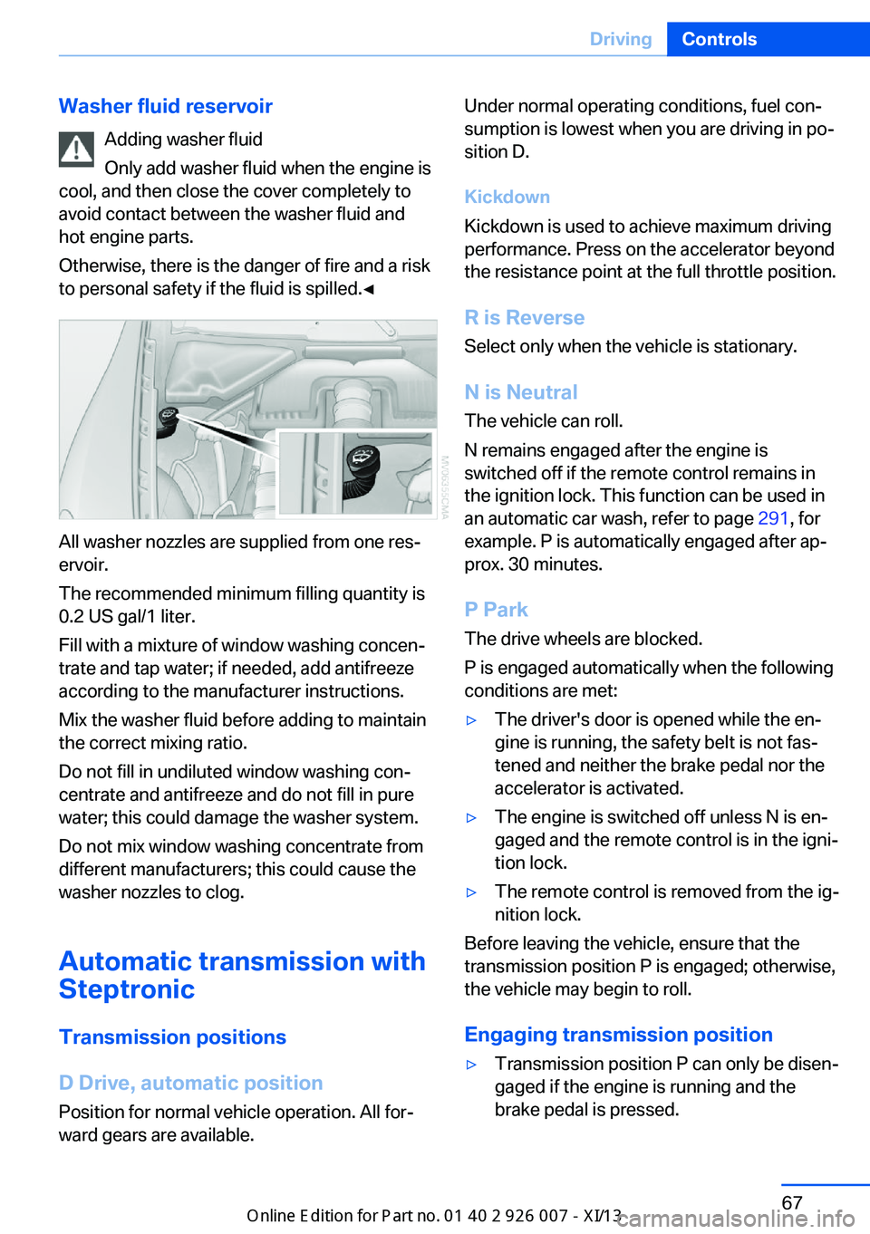
Washer fluid reservoirAdding washer fluid
Only add washer fluid when the engine is
cool, and then close the cover completely to
avoid contact between the washer fluid and
hot engine parts.
Otherwise, there is the danger of fire and a risk
to personal safety if the fluid is spilled.◀
All washer nozzles are supplied from one res‐
ervoir.
The recommended minimum filling quantity is
0.2 US gal/1 liter.
Fill with a mixture of window washing concen‐
trate and tap water; if needed, add antifreeze
according to the manufacturer instructions.
Mix the washer fluid before adding to maintain
the correct mixing ratio.
Do not fill in undiluted window washing con‐
centrate and antifreeze and do not fill in pure
water; this could damage the washer system.
Do not mix window washing concentrate from
different manufacturers; this could cause the
washer nozzles to clog.
Automatic transmission with
Steptronic
Transmission positions
D Drive, automatic position Position for normal vehicle operation. All for‐
ward gears are available.
Under normal operating conditions, fuel con‐
sumption is lowest when you are driving in po‐
sition D.
Kickdown
Kickdown is used to achieve maximum driving
performance. Press on the accelerator beyond
the resistance point at the full throttle position.
R is Reverse Select only when the vehicle is stationary.
N is Neutral The vehicle can roll.
N remains engaged after the engine is
switched off if the remote control remains in
the ignition lock. This function can be used in
an automatic car wash, refer to page 291, for
example. P is automatically engaged after ap‐
prox. 30 minutes.
P ParkThe drive wheels are blocked.
P is engaged automatically when the following
conditions are met:▷The driver's door is opened while the en‐
gine is running, the safety belt is not fas‐
tened and neither the brake pedal nor the
accelerator is activated.▷The engine is switched off unless N is en‐
gaged and the remote control is in the igni‐
tion lock.▷The remote control is removed from the ig‐
nition lock.
Before leaving the vehicle, ensure that the
transmission position P is engaged; otherwise,
the vehicle may begin to roll.
Engaging transmission position
▷Transmission position P can only be disen‐
gaged if the engine is running and the
brake pedal is pressed.Seite 67DrivingControls67
Online Edition for Part no. 01 40 2 910 876 - VII/13
Page 72 of 327

▷With the vehicle stationary, press on the
brake pedal before shifting out of P or N;
otherwise, the shift command will not be
executed: shift lock.
Press on the brake pedal until you start
driving
To prevent the vehicle from creeping after you
select a driving position, maintain pressure on
the brake pedal until you are ready to start.◀
Engaging transmission positions D, R,
N
Briefly push the selector lever in the desired di‐
rection, beyond a resistance point if necessary.
When shifting out of P or into R, simultane‐
ously push the unlock button 1.
The engaged transmission position is dis‐
played on the selector lever.
After releasing the selector lever, it returns to
its center position.
Engaging transmission position P Select only when the vehicle is stationary.
Press button P.
Sport program and manual mode M/S
Activating the Sport program
Push the selector lever to the left out of trans‐
mission position D.
The Sport program is activated and DS or the
engaged gear is displayed in the instrument
cluster, for example S4.
This position is recommended for a perform‐
ance-oriented driving style.
Activating manual mode
Push the selector lever to the left out of trans‐
mission position D.
Push the selector lever forward or backward.
Manual mode becomes active and the gear is
changed.
The engaged gear is displayed in the instru‐
ment cluster, e.g., M1.
▷To shift down: press the selector lever for‐
ward.▷To shift up: press the selector lever back‐
ward.
The transmission only shifts up or down if the
rpm and vehicle speed are appropriate. If the
engine speed is too high, the transmission
does not shift down.
The selected gear is briefly displayed in the in‐
strument panel, followed by the current gear.
Ending the Sport program/manual
mode
Push the selector lever to the right.
Seite 68ControlsDriving68
Online Edition for Part no. 01 40 2 910 876 - VII/13
Page 78 of 327

Resetting the trip computerResetting all values:1."Vehicle Info"2."Trip computer"3."Reset"
Service requirements
The remaining driving distance and the date of
the next scheduled service are displayed
briefly immediately after you start the engine
or switch on the ignition.
The current service requirements can be read
out from the remote control by the service
specialist.
For certain maintenance operations, you can
view the distance remaining or the due date for
that operation in the instrument cluster.
1.With the ignition switched on, press the
knob in the instrument cluster, refer to
page 70, for approx. 5 seconds until the
service requirements are displayed.2.Press the knob repeatedly to display the
individual service requirement items.DisplaysSymbolFunctionService requirementsEngine oilRoadworthiness testFront brake padsRear brake padsBrake fluid
The sequence of displayed service items may
vary. First the data for the next maintenance
are displayed.
Seite 74ControlsDisplays74
Online Edition for Part no. 01 40 2 910 876 - VII/13
Page 98 of 327

Switching on/off
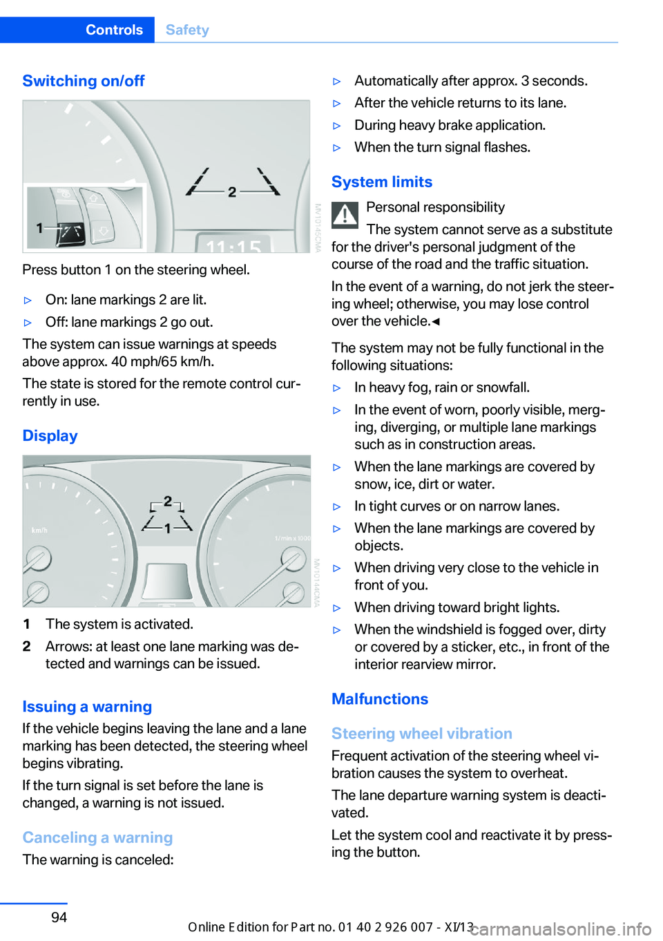
Press button 1 on the steering wheel.
▷On: lane markings 2 are lit.▷Off: lane markings 2 go out.
The system can issue warnings at speeds
above approx. 40 mph/65 km/h.
The state is stored for the remote control cur‐
rently in use.
Display
1The system is activated.2Arrows: at least one lane marking was de‐
tected and warnings can be issued.
Issuing a warning
If the vehicle begins leaving the lane and a lane
marking has been detected, the steering wheel
begins vibrating.
If the turn signal is set before the lane is
changed, a warning is not issued.
Canceling a warning The warning is canceled:
▷Automatically after approx. 3 seconds.▷After the vehicle returns to its lane.▷During heavy brake application.▷When the turn signal flashes.
System limits
Personal responsibility
The system cannot serve as a substitute
for the driver's personal judgment of the
course of the road and the traffic situation.
In the event of a warning, do not jerk the steer‐
ing wheel; otherwise, you may lose control
over the vehicle.◀
The system may not be fully functional in the
following situations:
▷In heavy fog, rain or snowfall.▷In the event of worn, poorly visible, merg‐
ing, diverging, or multiple lane markings
such as in construction areas.▷When the lane markings are covered by
snow, ice, dirt or water.▷In tight curves or on narrow lanes.▷When the lane markings are covered by
objects.▷When driving very close to the vehicle in
front of you.▷When driving toward bright lights.▷When the windshield is fogged over, dirty
or covered by a sticker, etc., in front of the
interior rearview mirror.
Malfunctions
Steering wheel vibration
Frequent activation of the steering wheel vi‐
bration causes the system to overheat.
The lane departure warning system is deacti‐
vated.
Let the system cool and reactivate it by press‐
ing the button.
Seite 94ControlsSafety94
Online Edition for Part no. 01 40 2 910 876 - VII/13
Page 99 of 327

Camera
The camera is located on the front of the inte‐
rior Rear View mirror.
Keep the area in front of the interior rearview
mirror clear.
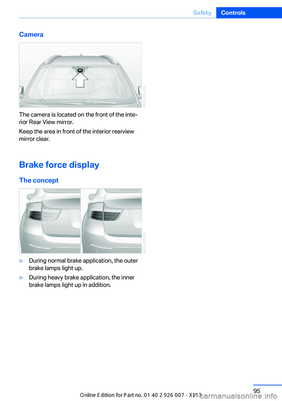
Brake force display The concept
▷During normal brake application, the outer
brake lamps light up.▷During heavy brake application, the inner
brake lamps light up in addition.Seite 95SafetyControls95
Online Edition for Part no. 01 40 2 910 876 - VII/13
Page 100 of 327

Driving stability control systemsVehicle equipmentThis chapter describes all series equipment as
well as country-specific and special equipment
offered for this model series.Therefore, it also
describes equipment that may not be found in
your vehicle, for instance due to the selected
special equipment or the country version. This
also applies to safety-related functions and
systems.
Antilock Brake System ABS
ABS prevents locking of the wheels during
braking.
The vehicle remains steerable even during full
brake applications, thus increasing active
safety.
ABS is operational every time you start the en‐
gine.
CBC Cornering Brake
Control
When braking during curves or when braking
during a lane change, driving stability and
steering response are improved further.
Electronic brake-force
distribution
The system controls the brake pressure in the
rear wheels to ensure stable braking behavior.
Brake assistantWhen you apply the brakes rapidly, this system
automatically produces the maximum braking
force boost. It thus helps to achieve the short‐
est possible braking distance during full brak‐ing. This system utilizes all of the benefits pro‐
vided by ABS.
Do not reduce the pressure on the brake pedal
for the duration of the full braking.
Dynamic Stability Control DSC
The concept
DSC prevents traction loss in the driving
wheels when driving away and accelerating.
DSC also recognizes unstable vehicle condi‐
tions, such as fishtailing or nose-diving. Sub‐
ject to physical limits, DSC helps to keep the
vehicle on a steady course by reducing engine
speed and by applying brakes to the individual
wheels.
Adjust your driving style to the situation
An appropriate driving style is always the
responsibility of the driver.
The laws of physics cannot be repealed, even
with DSC.
Do not reduce the additional safety margin
with a risky driving style, as otherwise there is
a risk of an accident.◀
Deactivating DSC: DSC OFF
When DSC is deactivated, driving stability is
reduced during acceleration and when driving
in bends.
To increase vehicle stability, activate DSC
again as soon as possible.Seite 96ControlsDriving stability control systems96
Online Edition for Part no. 01 40 2 910 876 - VII/13