2013 BMW X5M warning
[x] Cancel search: warningPage 42 of 345

start the engine: the engine cannot be started.
The remote control is not in the vehicle or has
a malfunction. Take the remote control with
you inside the vehicle or have it checked. If
necessary, insert another remote control into
the ignition switch.
The warning lamp in the instrumentcluster lights up while the engine is
running: the remote control is no lon‐
ger inside the vehicle.
After switching off the engine, the engine can
only be started again within approx. 10 sec‐
onds if no door has been opened.
The indicator lamp in the instrument
cluster comes on and a message ap‐
pears on the Control Display: replace
the remote control battery.
Replacing the battery
The remote control for Comfort Access con‐
tains a battery that will need to be replaced
from time to time.1.Take the integrated key out of the remote
control, refer to page 30.2.Remove the cover.3.Insert a new battery of the same type with
the positive side facing upwards.4.Press the cover closed.
Return used battery to a recycling collec‐
tion point or to your service center.
Alarm system
The conceptThe vehicle alarm system responds to:▷Opening of a door, the hood or the tailgate.▷Movements in the vehicle: interior motion
sensor, refer to page 43.▷Changes in the vehicle tilt, e.g., during at‐
tempts to steal a wheel or tow the car.▷Interruptions in battery voltage.
The alarm system briefly indicates tampering:
▷By sounding an acoustic alarm.▷By switching on the hazard warning sys‐
tem.▷By flashing the high beams.
Arming and disarming the alarm
system
General information
When you lock or unlock the vehicle, either
with the remote control or at the door lock, the
alarm system is armed or disarmed at the
same time.
Door lock and armed alarm systemUnlocking via the door lock will trigger the
alarm on some market-specific versions.
To stop this alarm, unlock the vehicle with the
remote control or switch on the ignition.
Tailgate and armed alarm system
The tailgate can be opened using the remote
control, even if the alarm system is armed.
Press the button on the remote control.
After the tailgate is closed, it is locked and
monitored again by the alarm system. The haz‐
ard warning system flashes once.
In some market-specific versions, the tailgate
can only be opened using the remote control if
the vehicle was unlocked first.
Seite 42ControlsOpening and closing42
Online Edition for Part no. 01 40 2 918 440 - III/13
Page 51 of 345
▷Increase or decrease curvature:
Press front or rear section of switch.▷Shift curvature up or down:
Press upper or lower section of switch.
BMW X5: rear seats
2nd row seats If the row of seats is divided, each side can be
adjusted separately.
Do not adjust the seat while driving
Never adjust the 2nd row seats while the
vehicle is moving, as otherwise the passengers
on the 3rd row seats could be injured.
Make sure that the locking devices of the 2nd
row seats engage properly. Otherwise the re‐
straining effect of the safety belts during an ac‐
cident could be reduced.◀
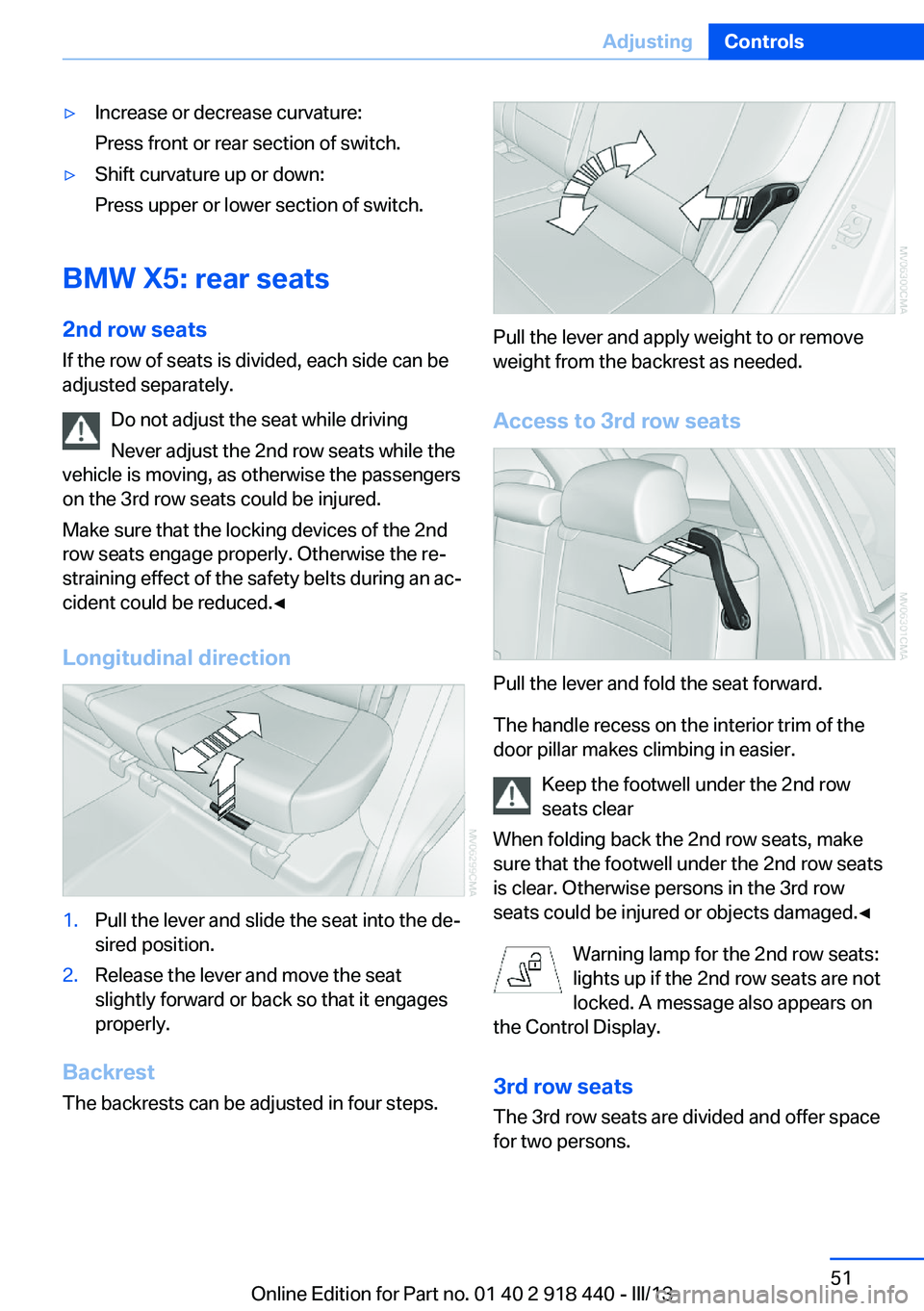
Longitudinal direction
1.Pull the lever and slide the seat into the de‐
sired position.2.Release the lever and move the seat
slightly forward or back so that it engages
properly.
Backrest
The backrests can be adjusted in four steps.
Pull the lever and apply weight to or remove
weight from the backrest as needed.
Access to 3rd row seats
Pull the lever and fold the seat forward.
The handle recess on the interior trim of the
door pillar makes climbing in easier.
Keep the footwell under the 2nd row
seats clear
When folding back the 2nd row seats, make
sure that the footwell under the 2nd row seats
is clear. Otherwise persons in the 3rd row
seats could be injured or objects damaged.◀
Warning lamp for the 2nd row seats:
lights up if the 2nd row seats are not
locked. A message also appears on
the Control Display.
3rd row seats
The 3rd row seats are divided and offer space
for two persons.
Seite 51AdjustingControls51
Online Edition for Part no. 01 40 2 918 440 - III/13
Page 55 of 345
Unbuckling the belt1.Hold the belt firmly.2.Press the red button in the belt buckle.3.Guide the belt back into its reel.
The shoulder strap's anchorage point will be
correct for adult seat occupants of every build
if the seat is correctly adjusted, refer to
page 49.
The two rear safety belt buckles integrated
into the rear seat are for passengers sitting on
the left and right. The belt buckle embossed
with the word CENTER is intended exclusively
for use by passengers riding in the center posi‐
tion.
Safety belt reminder for the driver's
and front passenger seat
The indicator lamp lights up and a
signal sounds. In addition, a message
appears on the Control Display.
Check whether the safety belt has been fas‐
tened correctly.
The safety belt reminder is active at speeds
above approx. 5 mph/8 km/h. It can also be ac‐
tivated if objects are placed on the front pas‐
senger seat.
Damage to safety belts In the case of strain caused by accidents or
damage:
Have the safety belts, including the safety belt
tensioners, replaced and have the belt anchors
checked.
Checking and replacing safety belts
Have the work performed only by your
service center; otherwise, it cannot be ensured
that this safety feature will function properly.◀
Belt-force limiter
The effect of the belt-force limiter on the driv‐
er's seat is dependent on the position of the
driver's seat.
To maintain the long-term accuracy of this
function, the driver's seat must be calibrated if
a corresponding message is displayed on the
Control Display.
Calibrating driver's seat The warning lamp lights up. A mes‐
sage also appears on the Control Dis‐
play. Please calibrate the driver's
seat.1.Move the driver's seat forward until it
stops.2.Move the driver's seat forward again. It
briefly moves toward the front in the proc‐
ess.3.Set the desired seating position again.
The calibration is completed when the mes‐
sage on the Control Display disappears.
Should this message continue to be displayed,
repeat the calibration. If the message does not
disappear even after repeated calibration, have
the system checked as soon as possible.
Do not carry out calibration while the ve‐
hicle is moving
Never carry out calibration while the vehicle is
moving, as this can cause accidents.
Make sure that no persons or objects become
wedged during the calibration process, as this
can cause injuries or damage.◀
Head restraints Correctly adjusted head restraints
A correctly adjusted head restraint reduces the
risk of spinal injury in the event of an accident.
Adjusting the head restraint
Correctly adjust the head restraints of all
occupied seats; otherwise, there is an in‐
creased risk of injury in an accident.◀
Seite 55AdjustingControls55
Online Edition for Part no. 01 40 2 918 440 - III/13
Page 68 of 345
Ignition onAll electrical consumers can operate. The od‐
ometer and trip odometer are displayed in the
instrument cluster.
To save battery power when the engine is off,
switch off the ignition and any unnecessary
electronic systems/power consumers.
Radio ready state and ignition off
All indicator and warning lamps as well as dis‐
plays in the instrument cluster go out.
Transmission position P with the ignition
off
When the ignition is switched off, position P is
engaged automatically. When in an automatic
car wash, for example, ensure that the ignition
is not switched off accidentally.◀
For example, the ignition is not switched off in
the following situations:▷The brake is applied.▷The low beams are switched on
Starting the engine
General information Enclosed areas
Do not let the engine run in enclosed
areas; otherwise, breathing of exhaust fumes
may lead to loss of consciousness and death.
The exhaust gases contain carbon monoxide,
an odorless and colorless but highly toxic
gas.◀
Unattended vehicle
Do not leave the car unattended with the
engine running; otherwise, it presents a poten‐
tial source of danger.
Before leaving the vehicle with the engine run‐
ning, set the parking brake and engage trans‐
mission position P; otherwise, the vehicle may
begin to roll.◀
Frequent starting in quick succession
Avoid repeated futile attempts at starting
the car and avoid starting the car frequently in
quick succession. Otherwise, the fuel is not
burned or is inadequately burned, and there is
the danger of overheating and damaging the
catalytic converter.◀
Do not wait for the engine to warm up while the
vehicle remains stationary. Start driving right
away, but at moderate engine speeds.
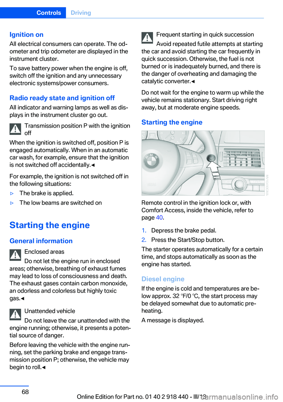
Starting the engine
Remote control in the ignition lock or, with
Comfort Access, inside the vehicle, refer to
page 40.
1.Depress the brake pedal.2.Press the Start/Stop button.
The starter operates automatically for a certain
time, and stops automatically as soon as the
engine has started.
Diesel engine
If the engine is cold and temperatures are be‐
low approx. 32 ℉/0 ℃, the start process may
be delayed somewhat due to automatic pre‐
heating.
A message is displayed.
Seite 68ControlsDriving68
Online Edition for Part no. 01 40 2 918 440 - III/13
Page 71 of 345
Automatic Hold is deactivated.
If the vehicle is being held by Automatic Hold,
then press on the brake pedal to deactivate it.
When the parking brake is set manually, refer
to page 69, Automatic Hold is deactivated au‐
tomatically.
Driving Automatic Hold is activated: the vehicle is au‐
tomatically secured against rolling when it
stops.
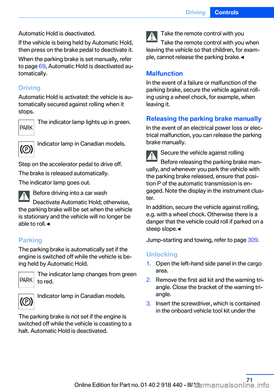
The indicator lamp lights up in green.
Indicator lamp in Canadian models.
Step on the accelerator pedal to drive off.
The brake is released automatically.
The indicator lamp goes out.
Before driving into a car wash
Deactivate Automatic Hold; otherwise,
the parking brake will be set when the vehicle
is stationary and the vehicle will no longer be
able to roll.◀
Parking
The parking brake is automatically set if the
engine is switched off while the vehicle is be‐
ing held by Automatic Hold.
The indicator lamp changes from green
to red.
Indicator lamp in Canadian models.
The parking brake is not set if the engine is
switched off while the vehicle is coasting to a
halt. Automatic Hold is deactivated.Take the remote control with you
Take the remote control with you when
leaving the vehicle so that children, for exam‐
ple, cannot release the parking brake.◀
Malfunction
In the event of a failure or malfunction of the
parking brake, secure the vehicle against roll‐
ing using a wheel chock, for example, when
leaving it.
Releasing the parking brake manually In the event of an electrical power loss or elec‐
trical malfunction, you can release the parking
brake manually.
Secure the vehicle against rolling
Before releasing the parking brake man‐
ually, and whenever you park the vehicle with
the parking brake released, ensure that posi‐
tion P of the automatic transmission is en‐
gaged. Note the display in the instrument clus‐
ter.
In addition, secure the vehicle against rolling,
e.g. with a wheel chock. Otherwise there is a
danger that the vehicle could roll if parked on a
steep slope.◀
Jump-starting and towing, refer to page 309.
Unlocking1.Open the left-hand side panel in the cargo
area.2.Remove the first aid kit and the warning tri‐
angle. Close the bracket of the warning tri‐
angle.3.Insert the screwdriver, which is contained
in the onboard vehicle tool kit under theSeite 71DrivingControls71
Online Edition for Part no. 01 40 2 918 440 - III/13
Page 72 of 345
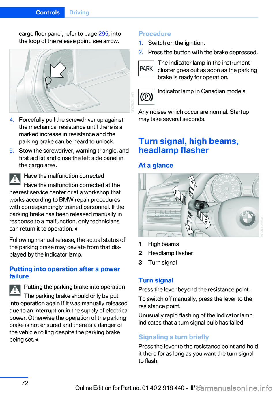
cargo floor panel, refer to page 295, into
the loop of the release point, see arrow.4.Forcefully pull the screwdriver up against
the mechanical resistance until there is a
marked increase in resistance and the
parking brake can be heard to unlock.5.Stow the screwdriver, warning triangle, and
first aid kit and close the left side panel in
the cargo area.
Have the malfunction corrected
Have the malfunction corrected at the
nearest service center or at a workshop that
works according to BMW repair procedures
with correspondingly trained personnel. If the
parking brake has been released manually in
response to a malfunction, only technicians
can return it to operation.◀
Following manual release, the actual status of
the parking brake may deviate from that dis‐
played by the indicator lamp.
Putting into operation after a power failure
Putting the parking brake into operation
The parking brake should only be put
into operation again if it was manually released
due to an interruption in the supply of electrical
power. Otherwise the operation of the parking
brake is not ensured and there is a danger of
the vehicle rolling despite the parking brake
being set.◀
Procedure1.Switch on the ignition.2.Press the button with the brake depressed.
The indicator lamp in the instrument
cluster goes out as soon as the parking
brake is ready for operation.
Indicator lamp in Canadian models.
Any noises which occur are normal. Startup
may take several seconds.
Turn signal, high beams,
headlamp flasher
At a glance
1High beams2Headlamp flasher3Turn signal
Turn signal
Press the lever beyond the resistance point.
To switch off manually, press the lever to the
resistance point.
Unusually rapid flashing of the indicator lamp
indicates that a turn signal bulb has failed.
Signaling a turn briefly
Press the lever to the resistance point and hold
it there for as long as you want the turn signal
to flash.
Seite 72ControlsDriving72
Online Edition for Part no. 01 40 2 918 440 - III/13
Page 79 of 345
DisplaysVehicle equipmentThis chapter describes all series equipment as
well as country-specific and special equipment
offered for this model series.Therefore, it also
describes equipment that may not be found in
your vehicle, for instance due to the selected
special equipment or the country version. This
also applies to safety-related functions and
systems.
Odometer, external
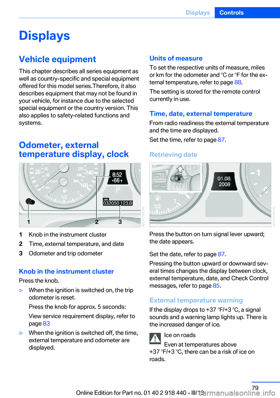
temperature display, clock1Knob in the instrument cluster2Time, external temperature, and date3Odometer and trip odometer
Knob in the instrument cluster
Press the knob.
▷When the ignition is switched on, the trip
odometer is reset.
Press the knob for approx. 5 seconds:
View service requirement display, refer to
page 83▷When the ignition is switched off, the time,
external temperature and odometer are
displayed.Units of measure
To set the respective units of measure, miles
or km for the odometer and ℃ or ℉ for the ex‐
ternal temperature, refer to page 88.
The setting is stored for the remote control
currently in use.
Time, date, external temperature From radio readiness the external temperature
and the time are displayed.
Set the time, refer to page 87.
Retrieving date
Press the button on turn signal lever upward;
the date appears.
Set the date, refer to page 87.
Pressing the button upward or downward sev‐
eral times changes the display between clock,
external temperature, date, and Check Control
messages, refer to page 85.
External temperature warning If the display drops to +37 ℉/+3 ℃, a signal
sounds and a warning lamp lights up. There is
the increased danger of ice.
Ice on roads
Even at temperatures above
+37 ℉/+3 ℃, there can be a risk of ice on
roads.
Seite 79DisplaysControls79
Online Edition for Part no. 01 40 2 918 440 - III/13
Page 80 of 345

Therefore, drive carefully on bridges and shady
roads, for example, to avoid the increased dan‐
ger of an accident.◀
Odometer and trip odometer
Resetting trip odometer:
With the ignition switched on, press button 1 in
the instrument cluster.
When the vehicle is parked If you still want to view the time, external tem‐
perature and odometer reading briefly after the
remote control has been taken out of the igni‐
tion lock:
Press button 1 in the instrument cluster.
Tachometer
Never force the engine speed up into the red
warning field, see arrow. In this range, the fuel
supply is interrupted to protect the engine.
Coolant temperature
A warning lamp will come on if the coolant, and
therefore the engine, becomes too hot. In addi‐
tion, a message will appear on the Control Dis‐
play.
Check the coolant level, refer to page 292.
Current fuel consumption
Displays the current fuel consumption. You
can check whether you are currently driving in
an efficient and environmentally-friendly man‐
ner.
Engine oil temperature
▷Cold engine: the pointer is at the low tem‐
perature end. Drive at moderate engine
and vehicle speeds.▷Normal operating temperature: the pointer
is in the middle or in the right half of the
temperature display.Seite 80ControlsDisplays80
Online Edition for Part no. 01 40 2 918 440 - III/13