2013 BMW X3 XDRIVE 28I turn signal
[x] Cancel search: turn signalPage 82 of 211
When the arrow view in the Head-up Display
is inactive.
Adjusting the info display
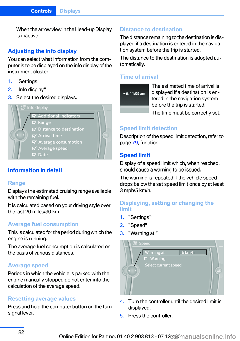
You can select what information from the com‐
puter is to be displayed on the info display of the
instrument cluster.
1."Settings"2."Info display"3.Select the desired displays.
Information in detail
Range
Displays the estimated cruising range available
with the remaining fuel.
It is calculated based on your driving style over
the last 20 miles/30 km.
Average fuel consumption
This is calculated for the period during which the
engine is running.
The average fuel consumption is calculated on
the basis of various distances.
Average speed
Periods in which the vehicle is parked with the
engine manually stopped do not enter into the
calculation of the average speed.
Resetting average values
Press and hold the computer button on the turn
signal lever.
Distance to destination
The distance remaining to the destination is dis‐
played if a destination is entered in the naviga‐
tion system before the trip is started.
The distance to the destination is adopted au‐
tomatically.
Time of arrival The estimated time of arrival is
displayed if a destination is en‐
tered in the navigation system
before the trip is started.
The time must be correctly set.
Speed limit detection
Description of the speed limit detection, refer to
page 79, function.
Speed limit
Display of a speed limit which, when reached,
should cause a warning to be issued.
The warning is repeated if the vehicle speed
drops below the set speed limit once by at least
3 mph/5 km/h.
Displaying, setting or changing the
limit1."Settings"2."Speed"3."Warning at:"4.Turn the controller until the desired limit is
displayed.5.Press the controller.Seite 82ControlsDisplays82
Online Edition for Part no. 01 40 2 903 813 - 07 12 490
Page 88 of 211

Adaptive light control
The concept
Adaptive light control is a variable headlamp
control system that enables dynamic illumina‐
tion of the road surface.
Depending on the steering angle and other pa‐
rameters, the light from the headlamp follows
the course of the road.
Activating
Switch position
with the ignition switched
on.
The turning lamps are automatically switched
on depending on the steering angle or the use
of turn signals.
To avoid blinding oncoming traffic, the Adaptive
Light Control does not swivel to the driver's side
when the vehicle is at a standstill.
When driving in reverse, only the turning lamp is
active.
Self-leveling headlights
The self-leveling headlights feature adapts the
light distribution to the contours of the road.
The light distribution is lowered on hilltops to
avoid blinding oncoming traffic and tilted in de‐
pressions to increase visibility.
Malfunction
A Check Control message is displayed.
Adaptive light control is malfunctioning or has
failed. Have the system checked as soon as pos‐
sible.
Headlamp range control
With halogen headlamps, the headlamp range of
the low beams can be manually adjusted for the
vehicle load to avoid blinding oncoming traffic.
The values following the slash apply to trailer
operation.
0 / 1 = 1 to 2 people without luggage.
1 / 1 = 5 people without luggage.
1 / 2 = 5 people with luggage.
2 / 2 = 1 person, full cargo area.
High-beam Assistant
The concept
If while in switch position
or the low
beams are automatically switched on, this sys‐
tem automatically switches the high beams on
and then off. The procedure is controlled by a
sensor on the front of the interior rearview mir‐
ror. The assistant ensures that the high beams
are switched on whenever the traffic situation
allows. The driver can intervene at any time and
switch the high beams on and off as usual.
Activating
1.Turn the light switch to or .2.Press the button on the turn signal lever, ar‐
row.
The indicator lamp in the instrument
cluster lights up.
When the lights are switched on, the
high beams are switched on and off automati‐
cally.
The system responds to light from oncoming
traffic and traffic driving ahead of you, and to ad‐
equate illumination, e.g., in towns and cities.
Seite 88ControlsLamps88
Online Edition for Part no. 01 40 2 903 813 - 07 12 490
Page 89 of 211
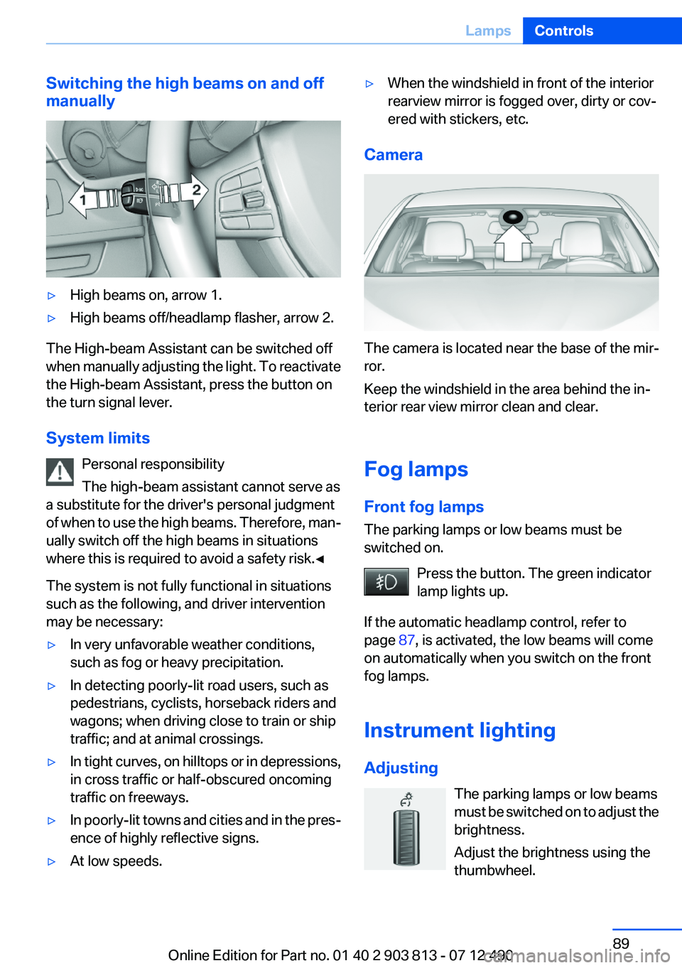
Switching the high beams on and off
manually▷High beams on, arrow 1.▷High beams off/headlamp flasher, arrow 2.
The High-beam Assistant can be switched off
when manually adjusting the light. To reactivate
the High-beam Assistant, press the button on
the turn signal lever.
System limits Personal responsibility
The high-beam assistant cannot serve as
a substitute for the driver's personal judgment
of when to use the high beams. Therefore, man‐
ually switch off the high beams in situations
where this is required to avoid a safety risk.◀
The system is not fully functional in situations
such as the following, and driver intervention
may be necessary:
▷In very unfavorable weather conditions,
such as fog or heavy precipitation.▷In detecting poorly-lit road users, such as
pedestrians, cyclists, horseback riders and
wagons; when driving close to train or ship
traffic; and at animal crossings.▷In tight curves, on hilltops or in depressions,
in cross traffic or half-obscured oncoming
traffic on freeways.▷In poorly-lit towns and cities and in the pres‐
ence of highly reflective signs.▷At low speeds.▷When the windshield in front of the interior
rearview mirror is fogged over, dirty or cov‐
ered with stickers, etc.
Camera
The camera is located near the base of the mir‐
ror.
Keep the windshield in the area behind the in‐
terior rear view mirror clean and clear.
Fog lamps
Front fog lamps
The parking lamps or low beams must be
switched on.
Press the button. The green indicator
lamp lights up.
If the automatic headlamp control, refer to
page 87, is activated, the low beams will come
on automatically when you switch on the front
fog lamps.
Instrument lighting
Adjusting The parking lamps or low beams
must be switched on to adjust the
brightness.
Adjust the brightness using the
thumbwheel.
Seite 89LampsControls89
Online Edition for Part no. 01 40 2 903 813 - 07 12 490
Page 99 of 211
Do this by checking the air pressure in all
four tires.
If the tire inflation pressure in all four tires is
correct, the Flat Tire Monitor may not have
been initialized. In this case, initialize the
system.
If an identification is not possible, please
contact the service center.2.Rectify the flat tire on the damaged wheel.
Run-flat tires
Maximum speed
You can continue driving with a damaged tire at
speeds up to 50 mph/80 km/h.
Continued driving with a flat tire
If continuing to drive with a damaged tire:
1.Avoid sudden braking and steering maneu‐
vers.2.Do not exceed a speed of 50 mph/80 km/h.3.Check the air pressure in all four tires at the
next opportunity.
If the tire inflation pressure in all four tires is
correct, the Flat Tire Monitor may not have
been initialized. In this case, initialize the
system.
Possible driving distance with complete loss of
tire inflation pressure:
The possible driving distance after a loss of tire
inflation pressure depends on the cargo load
and the driving style and conditions.
For a vehicle containing an average load, the
possible driving distance is approx.
50 miles/80 km.
When the vehicle is driven with a damaged tire,
its handling characteristics change, e.g., re‐
duced lane stability during braking, a longer
braking distance, and altered self-steering
properties. Adjust your driving style accord‐
ingly. Avoid abrupt steering maneuvers or driv‐
ing over obstacles, e.g., curbs, potholes, etc.
Because the possible driving distance depends
on how the vehicle is used during the trip, the
actual distance may be smaller or greater de‐
pending on the driving speed, road conditions,
external temperature, cargo load, etc.
Continued driving with a flat tire
Drive moderately and do not exceed a
speed of 50 mph/80 km/h.
A loss of tire inflation pressure results in a
change in the handling characteristics, e.g., re‐
duced lane stability during braking, a longer
braking distance and altered self-steering prop‐
erties.◀
Final tire failure
Vibrations or loud noises while driving can
indicate the final failure of the tire. Reduce speed
and stop; otherwise, pieces of the tire could
come loose and cause an accident. Do not con‐
tinue driving, and contact your service center. ◀
Lane departure warning
The concept
Starting at a specific speed, this system alerts
you when the vehicle on streets with lane mark‐
ings is about to leave the lane. Depending on the
country-specific version of the vehicle, the
speed is between 35 mph/55 km/h and
45 mph/70 km/h. When switching on the system
below this speed, a message appears in the in‐
strument cluster.
The steering wheel begins vibrating gently in the
event of warnings. The time of the warning may
vary depending on the current driving situation.
The system does not provide a warning if the
turn signal is set before leaving the lane.Seite 99SafetyControls99
Online Edition for Part no. 01 40 2 903 813 - 07 12 490
Page 100 of 211
NotesPersonal responsibility
The system cannot serve as a substitute
for the driver's personal judgment of the course
of the road and the traffic situation.
In the event of a warning, do not jerk the steering
wheel, as you may lose control of the vehicle.◀
At a glance
Button in the vehicle
Lane departure warning
Camera
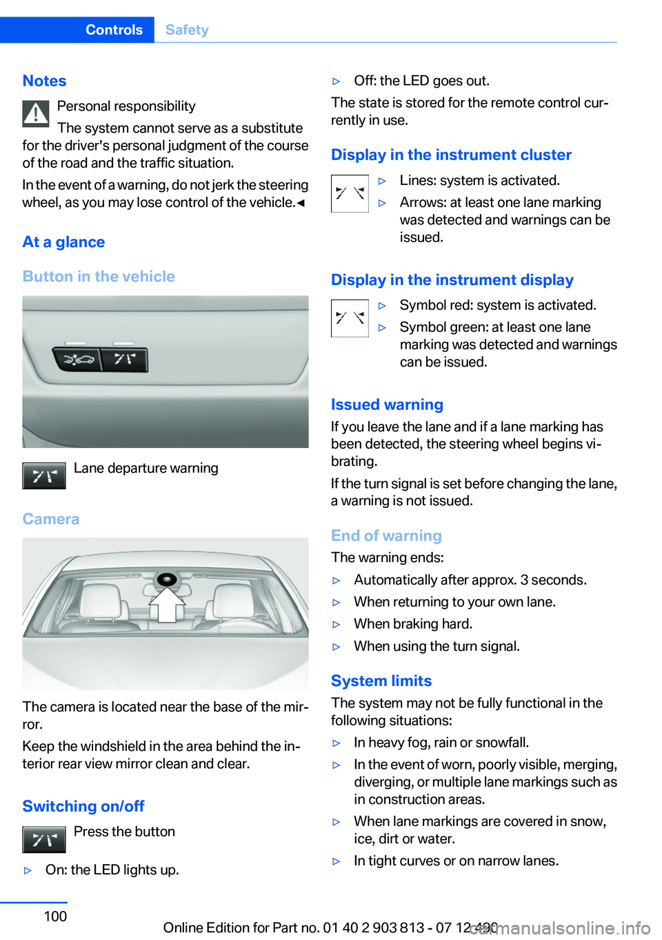
The camera is located near the base of the mir‐
ror.
Keep the windshield in the area behind the in‐
terior rear view mirror clean and clear.
Switching on/off Press the button
▷On: the LED lights up.▷Off: the LED goes out.
The state is stored for the remote control cur‐
rently in use.
Display in the instrument cluster
▷Lines: system is activated.▷Arrows: at least one lane marking
was detected and warnings can be
issued.
Display in the instrument display
▷Symbol red: system is activated.▷Symbol green: at least one lane
marking was detected and warnings
can be issued.
Issued warning
If you leave the lane and if a lane marking has
been detected, the steering wheel begins vi‐
brating.
If the turn signal is set before changing the lane,
a warning is not issued.
End of warning
The warning ends:
▷Automatically after approx. 3 seconds.▷When returning to your own lane.▷When braking hard.▷When using the turn signal.
System limits
The system may not be fully functional in the
following situations:
▷In heavy fog, rain or snowfall.▷In the event of worn, poorly visible, merging,
diverging, or multiple lane markings such as
in construction areas.▷When lane markings are covered in snow,
ice, dirt or water.▷In tight curves or on narrow lanes.Seite 100ControlsSafety100
Online Edition for Part no. 01 40 2 903 813 - 07 12 490
Page 172 of 211
Lamp and bulb replacement
Notes
Lamps and bulbs
Lamps and bulbs make an essential contribution
to vehicle safety.
The manufacturer of the vehicle recommends
that you entrust corresponding procedures to
the service center if you are unfamiliar with them
or they are not described here.
You can obtain a selection of replacement bulbs
at the service center.
Danger of burns
Only change bulbs when they are cool;
otherwise, there is the danger of getting
burned.◀
Working on the lighting system
When working on the lighting system, you
should always switch off the lights affected to
prevent short circuits.
To avoid possible injury or equipment damage
when replacing bulbs, observe any instructions
provided by the bulb manufacturer.◀
Do not perform work/bulb replacement on
xenon headlamps
Have any work on the xenon lighting system, in‐
cluding bulb replacement, performed only by a
service center. Due to the high voltage present
in the system, there is the danger of fatal injuries
if work is carried out improperly.◀
Do not touch the bulbs
Do not touch the glass of new bulbs with
your bare hands, as even minute amounts of
contamination will burn into the bulb's surface
and reduce its service life.
Use a clean tissue, cloth or something similar, or
hold the bulb by its base.◀Light-emitting diodes (LEDs)
Light-emitting diodes installed behind a cover
serve as the light source for controls, display el‐
ements and other equipment.
These light-emitting diodes, which are related
to conventional lasers, are officially designated
as Class 1 light-emitting diodes.
Do not remove the covers
Do not remove the covers, and never stare
into the unfiltered light for several hours; other‐
wise, irritation of the retina could result.◀
Headlamp glass
Condensation can form on the inside of the ex‐
ternal lamps in cool or humid weather. When
driving with the light switched on, the conden‐
sation evaporates after a short time. The head‐
lamp glasses do not need to be changed.
If the headlamps do not dim despite driving with
the light switched on, increasing humidity forms,
e. g. water droplets in the light, have the service
center check this.
Front lamps, bulb replacement
At a glance
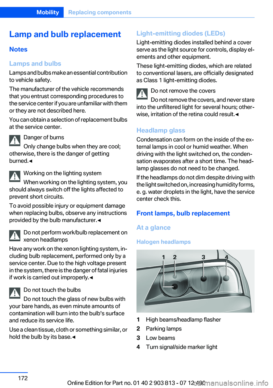
Halogen headlamps1High beams/headlamp flasher2Parking lamps3Low beams4Turn signal/side marker lightSeite 172MobilityReplacing components172
Online Edition for Part no. 01 40 2 903 813 - 07 12 490
Page 173 of 211
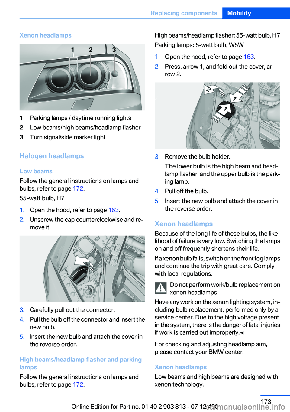
Xenon headlamps1Parking lamps / daytime running lights2Low beams/high beams/headlamp flasher3Turn signal/side marker light
Halogen headlamps
Low beams
Follow the general instructions on lamps and
bulbs, refer to page 172.
55-watt bulb, H7
1.Open the hood, refer to page 163.2.Unscrew the cap counterclockwise and re‐
move it.3.Carefully pull out the connector.4.Pull the bulb off the connector and insert the
new bulb.5.Insert the new bulb and attach the cover in
the reverse order.
High beams/headlamp flasher and parking
lamps
Follow the general instructions on lamps and
bulbs, refer to page 172.
High beams/headlamp flasher: 55-watt bulb, H7
Parking lamps: 5-watt bulb, W5W1.Open the hood, refer to page 163.2.Press, arrow 1, and fold out the cover, ar‐
row 2.3.Remove the bulb holder.
The lower bulb is the high beam and head‐
lamp flasher, and the upper bulb is the park‐
ing lamp.4.Pull off the bulb.5.Insert the new bulb and attach the cover in
the reverse order.
Xenon headlamps
Because of the long life of these bulbs, the like‐
lihood of failure is very low. Switching the lamps
on and off frequently shortens their life.
If a xenon bulb fails, switch on the front fog lamps
and continue the trip with great care. Comply
with local regulations.
Do not perform work/bulb replacement on
xenon headlamps
Have any work on the xenon lighting system, in‐
cluding bulb replacement, performed only by a
service center. Due to the high voltage present
in the system, there is the danger of fatal injuries
if work is carried out improperly.◀
For checking and adjusting headlamp aim,
please contact your BMW center.
Xenon headlamps
Low beams and high beams are designed with
xenon technology.
Seite 173Replacing componentsMobility173
Online Edition for Part no. 01 40 2 903 813 - 07 12 490
Page 174 of 211
The parking lamps and daylight running lights
are made using LED technology.
Contact your service center in the event of a
malfunction.
Front fog lamps
Follow the general instructions on lamps and
bulbs, refer to page 172.
Front fog lamps in vehicles equipped with Adap‐
tive Light Control: 55-watt bulb, H11
Front fog lamps without Adaptive Light Control:
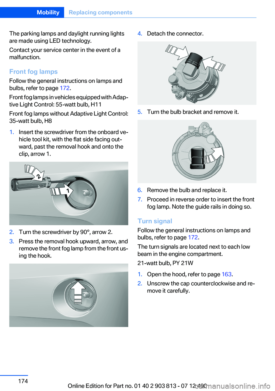
35-watt bulb, H81.Insert the screwdriver from the onboard ve‐
hicle tool kit, with the flat side facing out‐
ward, past the removal hook and onto the
clip, arrow 1.2.Turn the screwdriver by 90°, arrow 2.3.Press the removal hook upward, arrow, and
remove the front fog lamp from the front us‐
ing the hook.4.Detach the connector.5.Turn the bulb bracket and remove it.6.Remove the bulb and replace it.7.Proceed in reverse order to insert the front
fog lamp. Note the guide rails in doing so.
Turn signal
Follow the general instructions on lamps and
bulbs, refer to page 172.
The turn signals are located next to each low
beam in the engine compartment.
21-watt bulb, PY 21W
1.Open the hood, refer to page 163.2.Unscrew the cap counterclockwise and re‐
move it carefully.Seite 174MobilityReplacing components174
Online Edition for Part no. 01 40 2 903 813 - 07 12 490