2013 BMW X1 XDRIVE 35I tow
[x] Cancel search: towPage 24 of 291

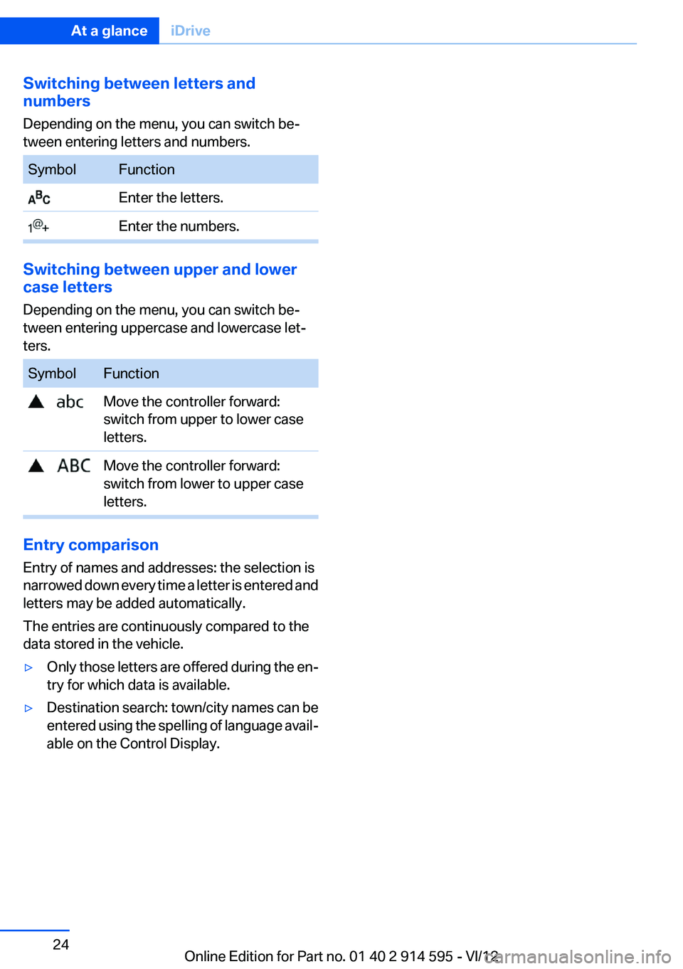
Switching between letters and
numbers
Depending on the menu, you can switch be‐
tween entering letters and numbers.SymbolFunction Enter the letters. Enter the numbers.
Switching between upper and lower
case letters
Depending on the menu, you can switch be‐
tween entering uppercase and lowercase let‐
ters.
SymbolFunction Move the controller forward:
switch from upper to lower case
letters. Move the controller forward:
switch from lower to upper case
letters.
Entry comparison
Entry of names and addresses: the selection is
narrowed down every time a letter is entered and
letters may be added automatically.
The entries are continuously compared to the
data stored in the vehicle.
▷Only those letters are offered during the en‐
try for which data is available.▷Destination search: town/city names can be
entered using the spelling of language avail‐
able on the Control Display.Seite 24At a glanceiDrive24
Online Edition for Part no. 01 40 2 914 595 - VI/12
Page 38 of 291

To switch the engine off with transmission po‐
sition N engaged, insert the remote control in
the ignition lock.
Malfunction
The Comfort Access functions can be disturbed
by local radio waves, such as by a mobile phone
in the immediate vicinity of the remote control or
when a mobile phone is being charged in the
vehicle.
If this occurs, open or close the vehicle using the
buttons on the remote control or use the
integrated key in the door lock.
To start the engine afterward, insert the remote
control into the ignition switch.
Warning lamps The warning lamp in the instrument
cluster lights up when you attempt to
start the engine: the engine cannot be
started.
The remote control is not in the vehicle or has a
malfunction. Take the remote control with you
inside the vehicle or have it checked. If neces‐
sary, insert another remote control into the ig‐
nition switch.
The warning lamp in the instrument
cluster lights up while the engine is
running: the remote control is no lon‐
ger inside the vehicle.
After switching off the engine, the engine can
only be started again within approx. 10 seconds
if no door has been opened.
The indicator lamp in the instrument
cluster comes on and a message ap‐
pears on the Control Display: replace
the remote control battery.Replacing the battery
The remote control for Comfort Access con‐
tains a battery that will need to be replaced from
time to time.1.Take the integrated key out of the remote
control, refer to page 30.2.Remove the cover.3.Insert a new battery of the same type with
the positive side facing upwards.4.Press the cover closed.
Return used battery to a recycling collec‐
tion point or to your service center.
Alarm system
The concept
The vehicle alarm system responds to:
▷Opening of a door, the hood or the tailgate.▷Movements in the vehicle: interior motion
sensor, refer to page 39.▷Changes in the vehicle tilt, e.g., during at‐
tempts to steal a wheel or tow the car.▷Interruptions in battery voltage.
The alarm system briefly indicates tampering:
▷By sounding an acoustic alarm.▷By switching on the hazard warning system.▷By flashing the high beams.Seite 38ControlsOpening and closing38
Online Edition for Part no. 01 40 2 914 595 - VI/12
Page 39 of 291

Arming and disarming the alarm
system
General information
When you lock or unlock the vehicle, either with
the remote control or at the door lock, the alarm
system is armed or disarmed at the same time.
Door lock and armed alarm system
Unlocking via the door lock will trigger the alarm
on some market-specific versions.
To stop this alarm, unlock the vehicle with the
remote control or switch on the ignition.
Tailgate and armed alarm system
The tailgate can be opened using the remote
control, even if the alarm system is armed.
Press the button on the remote control.
After the tailgate is closed, it is locked and moni‐
tored again by the alarm system. The hazard
warning system flashes once.
In some market-specific versions, the tailgate
can only be opened using the remote control if
the vehicle was unlocked first.
Switching off the alarm
▷Unlock the vehicle using the remote control,
refer to page 32.▷Insert the remote control all the way into the
ignition lock.
Indicator lamp on the interior rearview
mirror
▷The indicator lamp flashes briefly every
2 seconds:
The system is armed.▷The indicator lamp flashes after locking:
The doors, hood or tailgate is not closed
properly, but the rest of the vehicle is se‐
cured.
The indicator lamp flashes continuously af‐
ter approx. 10 seconds. The interior motion
sensor is not active.▷The indicator lamp goes out after unlocking:
The vehicle has not been tampered with.▷If the indicator lamp flashes after unlocking
until the remote control is inserted in the ig‐
nition, but for no longer than approx. 5 mi‐
nutes:
An alarm has been triggered.
Panic mode
In dangerous situations, trigger the alarm sys‐
tem:
Press the button on the remote control for at
least 3 seconds.
To switch off the alarm: press any button.
Tilt alarm sensor
The tilt of the vehicle is monitored.
The alarm system responds in situations such
as attempts to steal a wheel or tow the car.
Interior motion sensor
For the sensor to function properly, the windows
and panoramic glass sunroof must be closed.
Avoiding unintentional alarms
The tilt alarm sensor and interior motion sensor
can be switched off together, such as in the fol‐
lowing situations:
▷In duplex garages.▷During transport on car-carrying trains, at
sea or on a trailer.Seite 39Opening and closingControls39
Online Edition for Part no. 01 40 2 914 595 - VI/12
Page 63 of 291

A lock prevents you from inadvertently engaging
selector lever positions R and P. To cancel the
lock, press the button on the front of the selector
lever, see arrow.
P Park
Select only when the vehicle is stationary. The
rear wheels are locked.
R is Reverse
Select only when the vehicle is stationary.
N is Neutral
Use in automatic car washes, for example. The
vehicle can roll.
D Drive, automatic position
Position for normal vehicle operation. All for‐
ward gears are selected automatically.
Under normal operating conditions, fuel con‐
sumption is lowest when you are driving in po‐
sition D.
Kickdown
Kickdown is used to achieve maximum driving
performance. Press on the accelerator beyond
the resistance point at the full throttle position.
Sport program and manual mode M/S
Activating the Sport program
Move the selector lever from position D toward
the left.
DS is displayed in the instrument cluster.
This position is recommended for a perform‐
ance-oriented driving style.
To deactivate the Sport program or manual
mode M/S, move the selector lever to the right
into position D.
Activating the M/S manual mode
Move the selector lever from position D toward
the left.
Push the selector lever forward or backward.
Manual mode becomes active and the gear is
changed.
The engaged gear is displayed in the instrument
cluster, e.g., M1.
▷To shift down: press the selector lever for‐
ward.▷To shift up: press the selector lever back‐
ward.
The vehicle only shifts up or down at appropriate
engine and road speeds, e.g., it does not shift
down if the engine speed is too high. The se‐
lected gear is briefly displayed in the instrument
panel, followed by the current gear.
Seite 63DrivingControls63
Online Edition for Part no. 01 40 2 914 595 - VI/12
Page 82 of 291

The turning lamps are automatically switched
on depending on the steering angle or the use
of turn signals.
To avoid blinding oncoming traffic, the Adaptive
Light Control does not swivel to the driver's side
when the vehicle is at a standstill.
When driving in reverse, both turning lamps are
active.
Malfunction The warning lamp lights up.A mes‐
sage appears on the Control Display.
Adaptive light control is malfunction‐
ing or has failed. Have the system checked as
soon as possible.
High beams/roadside parking
lamps1High beams2Headlamp flasher3Roadside parking lamps
Left and right roadside parking lamps
The vehicle can be illuminated on one side.
Switching on
After parking the vehicle, press the lever up or
down beyond the resistance point for ap‐
prox. 2 seconds, arrow 3.
The roadside parking lamps drain the battery.
Therefore, do not leave them on for unduly long
periods of time; otherwise, the battery might not
have enough power to start the engine.
Switching off
Briefly press the lever in the opposite direction
to the pressure point, arrow 3.
High-beam Assistant
The concept
When the lights are switched on, this system
automatically switches the high beams on and
off. The procedure is controlled by a sensor on
the front of the interior rearview mirror. The as‐
sistant ensures that the high beams are
switched on whenever the traffic situation al‐
lows. The driver can intervene at any time and
switch the high beams on and off as usual.
Activating the High-beam Assistant1.Turn the light switch to .2.With the low beams switched on, briefly
push the turn indicator lever in the direction
of the high beam.
The indicator lamp in the instrument
cluster lights up. The high beams are
switched on and off automatically.
The system responds to light from oncoming
traffic and traffic driving ahead of you, and to ad‐
equate illumination, e.g., in towns and cities.
Switching the high beams on and off
manually
▷High beams on, arrow 1.Seite 82ControlsLamps82
Online Edition for Part no. 01 40 2 914 595 - VI/12
Page 83 of 291

▷High beams off/headlamp flasher, arrow 2.
To reactivate the High-beam Assistant, briefly
push the turn indicator lever toward the high
beams.
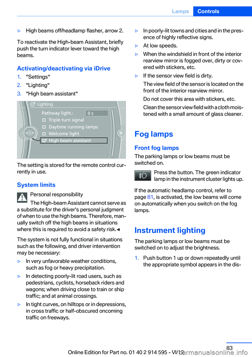
Activating/deactivating via iDrive
1."Settings"2."Lighting"3."High beam assistant"
The setting is stored for the remote control cur‐
rently in use.
System limits Personal responsibility
The High-beam Assistant cannot serve as
a substitute for the driver's personal judgment
of when to use the high beams. Therefore, man‐
ually switch off the high beams in situations
where this is required to avoid a safety risk.◀
The system is not fully functional in situations
such as the following, and driver intervention
may be necessary:
▷In very unfavorable weather conditions,
such as fog or heavy precipitation.▷In detecting poorly-lit road users, such as
pedestrians, cyclists, horseback riders and
wagons; when driving close to train or ship
traffic; and at animal crossings.▷In tight curves, on hilltops or in depressions,
in cross traffic or half-obscured oncoming
traffic on freeways.▷In poorly-lit towns and cities and in the pres‐
ence of highly reflective signs.▷At low speeds.▷When the windshield in front of the interior
rearview mirror is fogged over, dirty or cov‐
ered with stickers, etc.▷If the sensor view field is dirty.
The view field of the sensor is located on the
front of the interior rearview mirror.
Do not cover this area with stickers, etc.
Clean the sensor view field with a cloth mois‐
tened with a small amount of glass cleaner.
Fog lamps
Front fog lamps
The parking lamps or low beams must be
switched on.
Press the button. The green indicator
lamp in the instrument cluster lights up.
If the automatic headlamp control, refer to
page 81, is activated, the low beams will come
on automatically when you switch on the fog
lamps.
Instrument lighting
The parking lamps or low beams must be
switched on to adjust the brightness.
1.Push button 1 up or down repeatedly until
the appropriate symbol appears in the dis‐Seite 83LampsControls83
Online Edition for Part no. 01 40 2 914 595 - VI/12
Page 100 of 291

Park Distance Control PDC
The concept
In addition to the PDC Park Distance Control, the
backup camera, refer to page 102, can be
switched on.
PDC supports you when parking. A slow ap‐
proach to an object in front of or behind your ve‐
hicle is announced by:▷Signal tones.▷Visual display.
Measurement
Measurements are made by ultrasound sensors
in the bumpers.
The range is approx. 6 ft/2 m.
An acoustic warning is first given:
▷By the front sensors and two rear corner
sensors at approx. 24 in/60 cm.▷By the rear middle sensors at approx.
5 ft/1.50 m.
System limits
Check the traffic situation as well
PDC cannot serve as a substitute for the
driver's personal judgment of the traffic situa‐
tion. Check the traffic situation around the vehi‐
cle with your own eyes. Otherwise, an accident
could result from road users or objects located
outside of the PDC detection range.
Loud noises from outside and inside the vehicle
may prevent you from hearing the PDC's signal
tone.◀
Avoid driving quickly with PDC
Avoid approaching an object quickly.
Avoid driving away quickly while PDC is not yet
active.
For technical reasons, the system may other‐
wise be too late in issuing a warning.◀
Limits of ultrasonic measurement
The detection of objects can reach the physical
limits of ultrasonic measurement, for instance:▷With tow bars and trailer hitches.▷With thin or wedge-shaped objects.▷With low objects.▷With objects with corners and sharp edges.
Low objects already displayed, e.g., curbs, can
move into the blind area of the sensors before or
after a continuous tone sounds.
High, protruding objects such as ledges may not
be detected.
False warnings
PDC may issue a warning under the following
conditions even though there is no obstacle
within the detection range:
▷In heavy rain.▷When sensors are very dirty or covered in
ice.▷When sensors are covered in snow.▷On rough road surfaces.▷In large buildings with right angles and
smooth walls, e.g., in underground garages.▷In heavy exhaust.▷Due to other ultrasound sources, e.g.,
sweeping machines, high pressure steam
cleaners or neon lights.
Switching on automatically
With the engine running or the ignition switched
on, shift the selector lever into position R.
Switching off automatically when
driving forward
The system switches off when a certain distance
or speed is exceeded.
Switch on the system again if necessary.
Seite 100ControlsDriving comfort100
Online Edition for Part no. 01 40 2 914 595 - VI/12
Page 116 of 291

Observe the instructions concerning the
safety belt
Observe the instructions concerning the safety
belt, refer to page 45. Otherwise, personal pro‐
tection may be compromised.◀
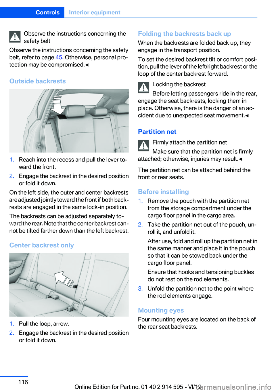
Outside backrests1.Reach into the recess and pull the lever to‐
ward the front.2.Engage the backrest in the desired position
or fold it down.
On the left side, the outer and center backrests
are adjusted jointly toward the front if both back‐
rests are engaged in the same lock-in position.
The backrests can be adjusted separately to‐
ward the rear. Note that the center backrest can‐
not be tilted farther down than the left backrest.
Center backrest only
1.Pull the loop, arrow.2.Engage the backrest in the desired position
or fold it down.Folding the backrests back up
When the backrests are folded back up, they
engage in the transport position.
To set the desired backrest tilt or comfort posi‐
tion, pull the lever of the left/right backrest or the
loop of the center backrest forward.
Locking the backrest
Before letting passengers ride in the rear,
engage the seat backrests, locking them in
place. Otherwise, there is the danger of an ac‐
cident due to unexpected seat movement.◀
Partition net Firmly attach the partition net
Make sure that the partition net is firmly
attached; otherwise, injuries may result.◀
The partition net can be attached behind the
front or rear seats.
Before installing1.Remove the pouch with the partition net
from the storage compartment under the
cargo floor panel in the cargo area.2.Take the partition net out of the pouch, un‐
roll it, and unfold it.
After use, fold and roll up the partition net in
the same manner and place it in the pouch
so that it can be stowed back under the
cargo floor panel.
Ensure that hooks and tensioning buckles
do not rest on the rod elements.3.Unfold the partition net to the point where
the rod elements engage.
Mounting eyes
Four mounting eyes are located on the back of
the rear seat backrests.
Seite 116ControlsInterior equipment116
Online Edition for Part no. 01 40 2 914 595 - VI/12