2013 BMW X1 XDRIVE 35I instrument cluster
[x] Cancel search: instrument clusterPage 77 of 291

To exit from the menu:
Move the controller to the left.
Automatic Service Request
Data regarding the maintenance status or legally
mandated inspections of the vehicle are auto‐
matically transmitted to your service center be‐
fore a service due date.
You can check when your service center was
notified.1."Vehicle Info"2."Vehicle status"3.Open "Options".4."Last Service Request"
Check Control
The concept
The Check Control monitors vehicle functions
and alerts you to any malfunctions in the sys‐
tems monitored.
A Check Control message consists of indicator
and warning lamps in the instrument cluster and,
in some circumstances, an acoustic signal and
text messages at the top of the Control Display.
Indicator/warning lamps
The indicator and warning lamps can light up in
a variety of combinations and colors.
Several of the lamps are checked for proper
functioning and light up temporarily when the
engine is started or the ignition is switched on.
The symbol indicates that Check Control
messages have been stored. The Check Control
messages can be displayed later.
Text messages
Text messages at the upper edge of the Control
Display in combination with a symbol in the in‐
strument cluster explain a Check Control mes‐
sage and the meaning of the indicator and warn‐
ing lamps.
Supplementary text messages
Addition information, such as on the cause of a
fault or the required action, can be called up via
Check Control.
In urgent cases, this information will be shown
as soon as the corresponding lamp comes on.
Symbols
The following functions can be selected within
the supplementary text message, depending on
the Check Control message.
▷ "Service request"
Contact the service partner.▷ "Roadside Assistance"
Contact Roadside Assistance.Seite 77DisplaysControls77
Online Edition for Part no. 01 40 2 914 595 - VI/12
Page 82 of 291

The turning lamps are automatically switched
on depending on the steering angle or the use
of turn signals.
To avoid blinding oncoming traffic, the Adaptive
Light Control does not swivel to the driver's side
when the vehicle is at a standstill.
When driving in reverse, both turning lamps are
active.
Malfunction The warning lamp lights up.A mes‐
sage appears on the Control Display.
Adaptive light control is malfunction‐
ing or has failed. Have the system checked as
soon as possible.
High beams/roadside parking
lamps1High beams2Headlamp flasher3Roadside parking lamps
Left and right roadside parking lamps
The vehicle can be illuminated on one side.
Switching on
After parking the vehicle, press the lever up or
down beyond the resistance point for ap‐
prox. 2 seconds, arrow 3.
The roadside parking lamps drain the battery.
Therefore, do not leave them on for unduly long
periods of time; otherwise, the battery might not
have enough power to start the engine.
Switching off
Briefly press the lever in the opposite direction
to the pressure point, arrow 3.
High-beam Assistant
The concept
When the lights are switched on, this system
automatically switches the high beams on and
off. The procedure is controlled by a sensor on
the front of the interior rearview mirror. The as‐
sistant ensures that the high beams are
switched on whenever the traffic situation al‐
lows. The driver can intervene at any time and
switch the high beams on and off as usual.
Activating the High-beam Assistant1.Turn the light switch to .2.With the low beams switched on, briefly
push the turn indicator lever in the direction
of the high beam.
The indicator lamp in the instrument
cluster lights up. The high beams are
switched on and off automatically.
The system responds to light from oncoming
traffic and traffic driving ahead of you, and to ad‐
equate illumination, e.g., in towns and cities.
Switching the high beams on and off
manually
▷High beams on, arrow 1.Seite 82ControlsLamps82
Online Edition for Part no. 01 40 2 914 595 - VI/12
Page 83 of 291
▷High beams off/headlamp flasher, arrow 2.
To reactivate the High-beam Assistant, briefly
push the turn indicator lever toward the high
beams.
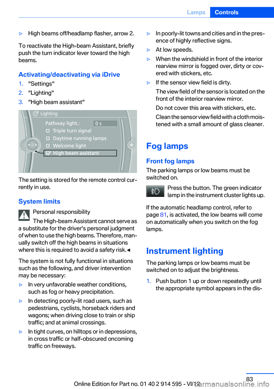
Activating/deactivating via iDrive
1."Settings"2."Lighting"3."High beam assistant"
The setting is stored for the remote control cur‐
rently in use.
System limits Personal responsibility
The High-beam Assistant cannot serve as
a substitute for the driver's personal judgment
of when to use the high beams. Therefore, man‐
ually switch off the high beams in situations
where this is required to avoid a safety risk.◀
The system is not fully functional in situations
such as the following, and driver intervention
may be necessary:
▷In very unfavorable weather conditions,
such as fog or heavy precipitation.▷In detecting poorly-lit road users, such as
pedestrians, cyclists, horseback riders and
wagons; when driving close to train or ship
traffic; and at animal crossings.▷In tight curves, on hilltops or in depressions,
in cross traffic or half-obscured oncoming
traffic on freeways.▷In poorly-lit towns and cities and in the pres‐
ence of highly reflective signs.▷At low speeds.▷When the windshield in front of the interior
rearview mirror is fogged over, dirty or cov‐
ered with stickers, etc.▷If the sensor view field is dirty.
The view field of the sensor is located on the
front of the interior rearview mirror.
Do not cover this area with stickers, etc.
Clean the sensor view field with a cloth mois‐
tened with a small amount of glass cleaner.
Fog lamps
Front fog lamps
The parking lamps or low beams must be
switched on.
Press the button. The green indicator
lamp in the instrument cluster lights up.
If the automatic headlamp control, refer to
page 81, is activated, the low beams will come
on automatically when you switch on the fog
lamps.
Instrument lighting
The parking lamps or low beams must be
switched on to adjust the brightness.
1.Push button 1 up or down repeatedly until
the appropriate symbol appears in the dis‐Seite 83LampsControls83
Online Edition for Part no. 01 40 2 914 595 - VI/12
Page 95 of 291
indicator lamp for DSC lights up in the instru‐
ment cluster and DSC OFF is displayed. DTC
Dynamic Traction Control and DSC are deacti‐
vated together.
In the interest of better forward momentum,
brake intervention is performed in the manner of
a differential lock when the drive wheels spin
quickly even if DSC is deactivated.
Activating DSC Press the button.
DSC OFF and the indicator lamp in the
instrument cluster go out.
For better control The indicator lamp flashes: DSC con‐
trols the drive forces and brake forces.
The indicator lamp lights up: DSC and
DTC has failed.
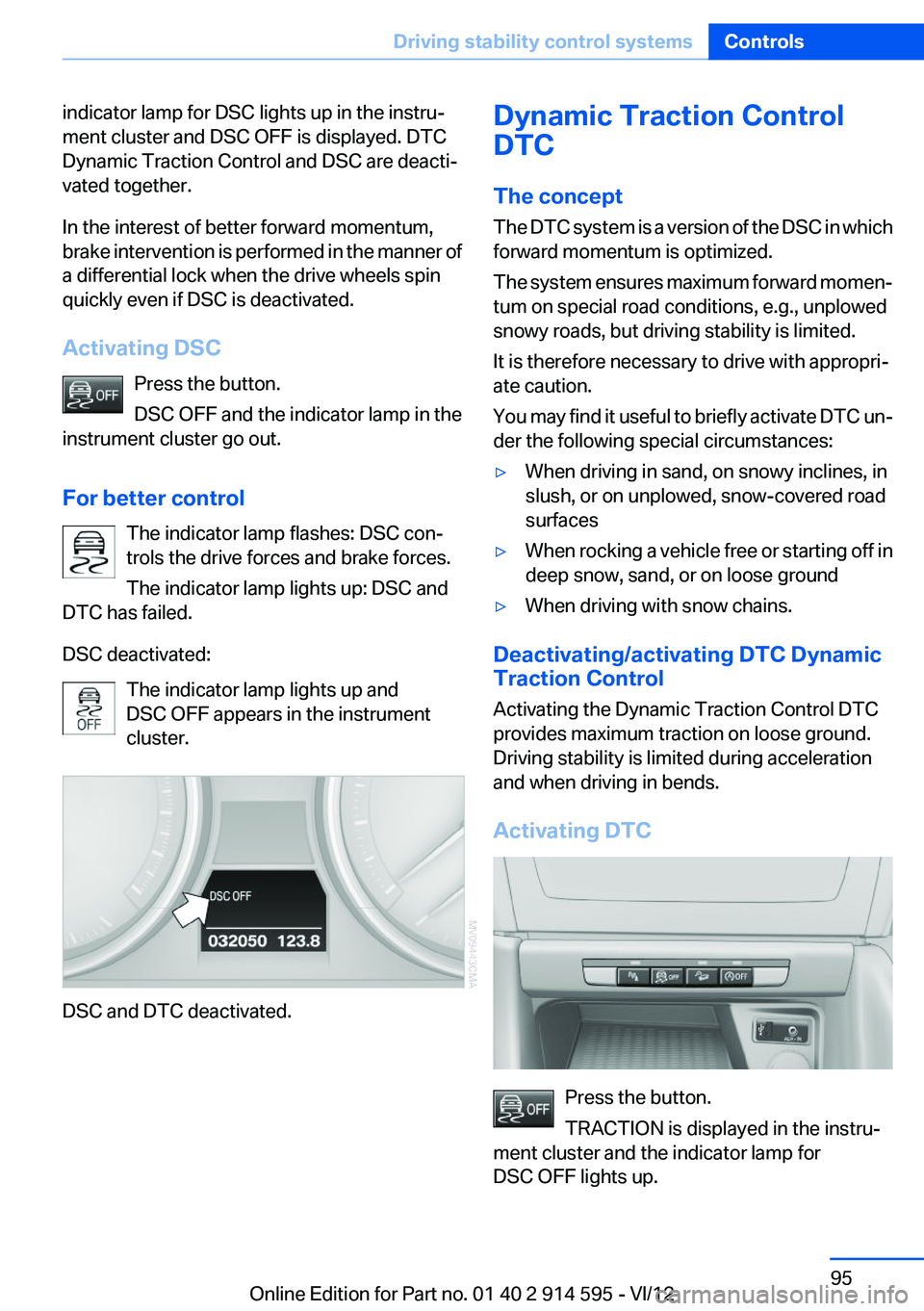
DSC deactivated: The indicator lamp lights up and
DSC OFF appears in the instrument
cluster.
DSC and DTC deactivated.
Dynamic Traction Control
DTC
The concept
The DTC system is a version of the DSC in which
forward momentum is optimized.
The system ensures maximum forward momen‐
tum on special road conditions, e.g., unplowed
snowy roads, but driving stability is limited.
It is therefore necessary to drive with appropri‐
ate caution.
You may find it useful to briefly activate DTC un‐
der the following special circumstances:▷When driving in sand, on snowy inclines, in
slush, or on unplowed, snow-covered road
surfaces▷When rocking a vehicle free or starting off in
deep snow, sand, or on loose ground▷When driving with snow chains.
Deactivating/activating DTC Dynamic
Traction Control
Activating the Dynamic Traction Control DTC
provides maximum traction on loose ground.
Driving stability is limited during acceleration
and when driving in bends.
Activating DTC
Press the button.
TRACTION is displayed in the instru‐
ment cluster and the indicator lamp for
DSC OFF lights up.
Seite 95Driving stability control systemsControls95
Online Edition for Part no. 01 40 2 914 595 - VI/12
Page 96 of 291
Deactivating DTCPress the button again.
TRACTION and the indicator lamp in
the instrument cluster go out.
For better control The indicator lamp flashes: DTC con‐
trols the drive forces and brake forces.
The indicator lamp lights up: DSC and
DTC has failed.
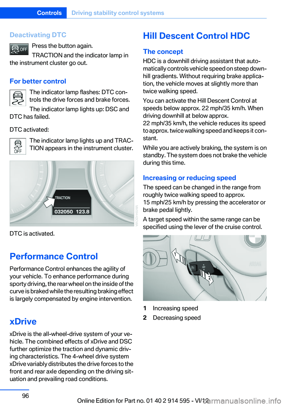
DTC activated: The indicator lamp lights up and TRAC‐
TION appears in the instrument cluster.
DTC is activated.
Performance Control
Performance Control enhances the agility of
your vehicle. To enhance performance during
sporty driving, the rear wheel on the inside of the
curve is braked while the resulting braking effect
is largely compensated by engine intervention.
xDrive
xDrive is the all-wheel-drive system of your ve‐
hicle. The combined effects of xDrive and DSC
further optimize the traction and dynamic driv‐
ing characteristics. The 4-wheel drive system
xDrive variably distributes the drive forces to the
front and rear axle depending on the driving sit‐
uation and prevailing road conditions.
Hill Descent Control HDC
The concept
HDC is a downhill driving assistant that auto‐
matically controls vehicle speed on steep down‐
hill gradients. Without requiring brake applica‐
tion, the vehicle moves at slightly more than
twice walking speed.
You can activate the Hill Descent Control at
speeds below approx. 22 mph/35 km/h. When
driving downhill at below approx.
22 mph/35 km/h, the vehicle reduces its speed
to approx. twice walking speed and keeps it con‐
stant.
While you are actively braking, the system is on
standby. The system does not brake the vehicle
during this time.
Increasing or reducing speed
The speed can be changed in the range from
roughly twice walking speed to approx.
15 mph/25 km/h by pressing the accelerator or
brake pedal lightly.
A target speed within the same range can be
specified using the lever of the cruise control.1Increasing speed2Decreasing speedSeite 96ControlsDriving stability control systems96
Online Edition for Part no. 01 40 2 914 595 - VI/12
Page 97 of 291
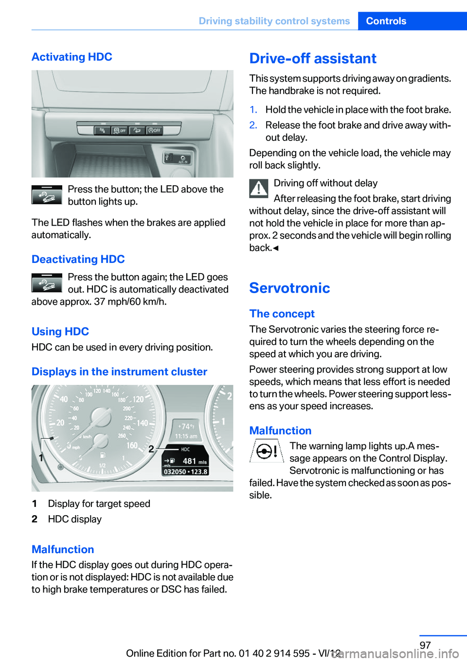
Activating HDC
Press the button; the LED above the
button lights up.
The LED flashes when the brakes are applied
automatically.
Deactivating HDC Press the button again; the LED goes
out. HDC is automatically deactivated
above approx. 37 mph/60 km/h.
Using HDC
HDC can be used in every driving position.
Displays in the instrument cluster
1Display for target speed2HDC display
Malfunction
If the HDC display goes out during HDC opera‐
tion or is not displayed: HDC is not available due
to high brake temperatures or DSC has failed.
Drive-off assistant
This system supports driving away on gradients.
The handbrake is not required.1.Hold the vehicle in place with the foot brake.2.Release the foot brake and drive away with‐
out delay.
Depending on the vehicle load, the vehicle may
roll back slightly.
Driving off without delay
After releasing the foot brake, start driving
without delay, since the drive-off assistant will
not hold the vehicle in place for more than ap‐
prox. 2 seconds and the vehicle will begin rolling
back.◀
Servotronic
The concept
The Servotronic varies the steering force re‐
quired to turn the wheels depending on the
speed at which you are driving.
Power steering provides strong support at low
speeds, which means that less effort is needed
to turn the wheels. Power steering support less‐
ens as your speed increases.
Malfunction The warning lamp lights up.A mes‐
sage appears on the Control Display.
Servotronic is malfunctioning or has
failed. Have the system checked as soon as pos‐
sible.
Seite 97Driving stability control systemsControls97
Online Edition for Part no. 01 40 2 914 595 - VI/12
Page 98 of 291
Driving comfortVehicle equipment
This chapter describes all series equipment as
well as country-specific and special equipment
offered for this model series.Therefore, it also
describes equipment that may not be found in
your vehicle, for instance due to the selected
special equipment or the country version. This
also applies to safety-related functions and sys‐
tems.
Cruise control
The concept
The system is functional at speeds beginning at
approx. 20 mph/30 km/h.
The speed specified using the lever on the
steering column is maintained.
The system brakes on downhill gradients if en‐
gine braking action is insufficient.
Do not use cruise control
Do not use the system if unfavorable con‐
ditions make it impossible to drive at a constant
speed, for instance:▷On curvy roads.▷In heavy traffic.▷On slippery roads, in fog, snow or rain, or on
a loose road surface.
Otherwise, you could lose control of the vehicle
and cause an accident.◀
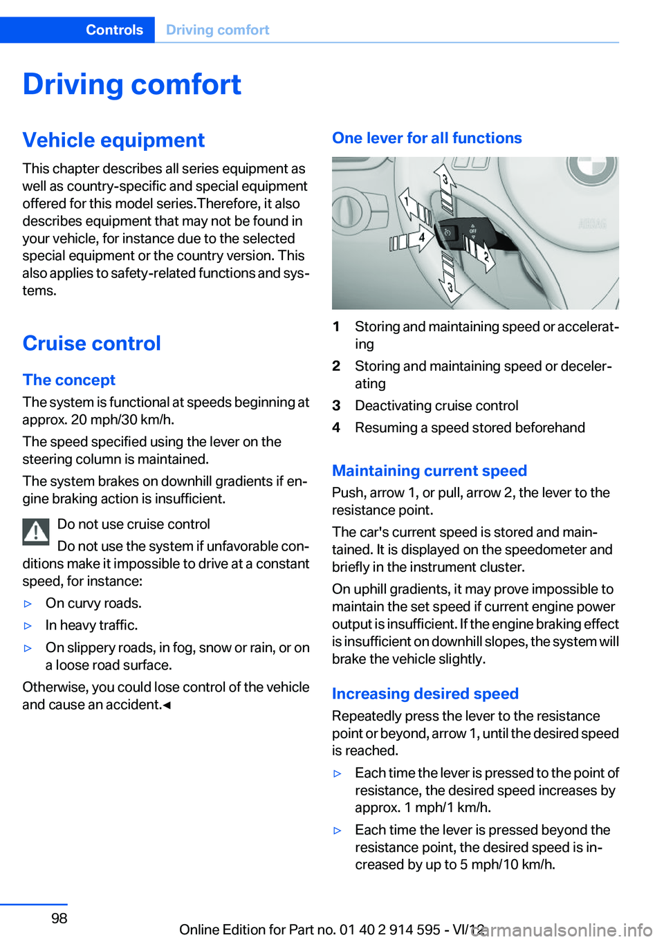
One lever for all functions1Storing and maintaining speed or accelerat‐
ing2Storing and maintaining speed or deceler‐
ating3Deactivating cruise control4Resuming a speed stored beforehand
Maintaining current speed
Push, arrow 1, or pull, arrow 2, the lever to the
resistance point.
The car's current speed is stored and main‐
tained. It is displayed on the speedometer and
briefly in the instrument cluster.
On uphill gradients, it may prove impossible to
maintain the set speed if current engine power
output is insufficient. If the engine braking effect
is insufficient on downhill slopes, the system will
brake the vehicle slightly.
Increasing desired speed
Repeatedly press the lever to the resistance
point or beyond, arrow 1, until the desired speed
is reached.
▷Each time the lever is pressed to the point of
resistance, the desired speed increases by
approx. 1 mph/1 km/h.▷Each time the lever is pressed beyond the
resistance point, the desired speed is in‐
creased by up to 5 mph/10 km/h.Seite 98ControlsDriving comfort98
Online Edition for Part no. 01 40 2 914 595 - VI/12
Page 99 of 291
The system stores and maintains the speed.
Accelerating using the lever
Accelerating slightly:
Press the lever to the resistance point, arrow 1,
until the desired speed is reached.
Accelerating significantly:
Press the lever beyond the resistance point, ar‐
row 1, until the desired speed is reached.
The vehicle accelerates without pressure on the
accelerator pedal. The system stores and main‐
tains the speed.
Decreasing speed
Repeatedly pull the lever to the resistance point
or beyond, arrow 2, until the desired speed is
displayed.▷Each time the lever is pulled to the resist‐
ance point, the desired speed is decreased
by approx. 1 mph/1 km/h.▷Each time the lever is pulled beyond the re‐
sistance point, the desired speed is reduced
by up to 5 mph/10 km/h until the minimum
speed of 20 mph/30 km/h is achieved.
The system stores and maintains the speed.
Deactivating cruise control
Push the lever upwards or downwards, arrow 3.
The displays in the speedometer go out.
In addition, the system is automatically deacti‐
vated when:
▷The brakes are applied.▷Selector lever position N is engaged or
transmission position D is disengaged.▷When DTC is activated or DSC is deacti‐
vated.▷When DSC or ABS is intervening.
Cruise control is not deactivated by depressing
the accelerator pedal. Once the accelerator
pedal is released, the stored speed is achieved
again and maintained.
Warning lamp
The warning lamp comes on when
cruise control has been deactivated as
a result of DSC intervention, for exam‐
ple. A message appears on the Control Display.
Resuming a speed stored beforehand
Press the button, arrow 4. The last stored speed
is resumed and maintained.
In the following cases, the stored speed value is
deleted and cannot be called up again:▷When driving stability control systems inter‐
vene.▷When selector lever position N is engaged
or transmission position D is disengaged.▷When the ignition is switched off.
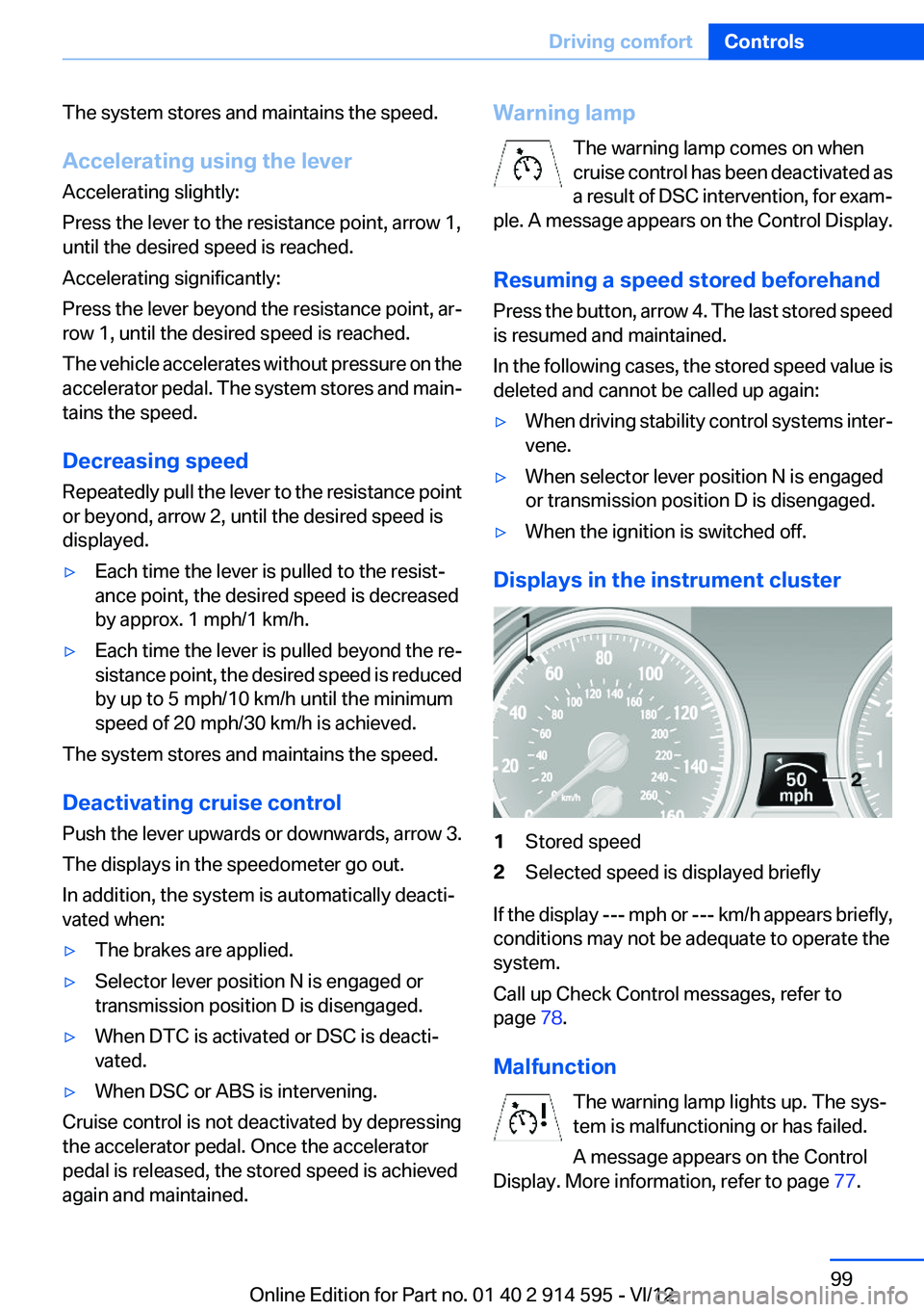
Displays in the instrument cluster
1Stored speed2Selected speed is displayed briefly
If the display --- mph or --- km/h appears briefly,
conditions may not be adequate to operate the
system.
Call up Check Control messages, refer to
page 78.
Malfunction The warning lamp lights up. The sys‐
tem is malfunctioning or has failed.
A message appears on the Control
Display. More information, refer to page 77.
Seite 99Driving comfortControls99
Online Edition for Part no. 01 40 2 914 595 - VI/12