2013 BMW X1 XDRIVE 35I brake
[x] Cancel search: brakePage 58 of 291

Activating/deactivating the system
manually
Press the button.
▷LED lights up: the Auto Start/Stop function
is deactivated.
The engine is started during an automatic
engine stop.
The engine can only be stopped or started
via the Start/Stop button.▷LED goes out: the Auto Start/Stop function
is activated.
Automatic deactivation
In certain situations, the Auto Start/Stop func‐
tion is deactivated automatically in the interest
of safety, for example if the driver's absence is
detected.
Malfunction The indicator lamp lights up. The au‐
tomatic engine start/stop function no
longer switches of the engine auto‐
matically.A message appears on the Control
Display. It is possible to continue driving. Have
the system checked.
Handbrake
The concept
The handbrake is primarily intended to prevent
the vehicle from rolling while parked; it brakes
the rear wheels.
Indicator lamp
The indicator lamp lights up and an
acoustic signal sounds when driving
away. The handbrake is still set.
Setting
The lever engages automatically.
Releasing
Pull up slightly, press the button, and lower the
lever.
Notes Using the handbrake while driving
If it should become necessary to use the
handbrake while driving, do not pull the hand‐
brake too forcefully. Keep the button on the
handbrake lever pressed at all times.
Excessive application of the handbrake can
block the rear wheels and lead to fishtailing of
the vehicle.◀
To prevent corrosion and uneven brake action,
lightly apply the handbrake from time to time
when coasting, traffic conditions permitting.
The brake lamps do not light up when the hand‐
brake is pulled.
Seite 58ControlsDriving58
Online Edition for Part no. 01 40 2 914 595 - VI/12
Page 62 of 291
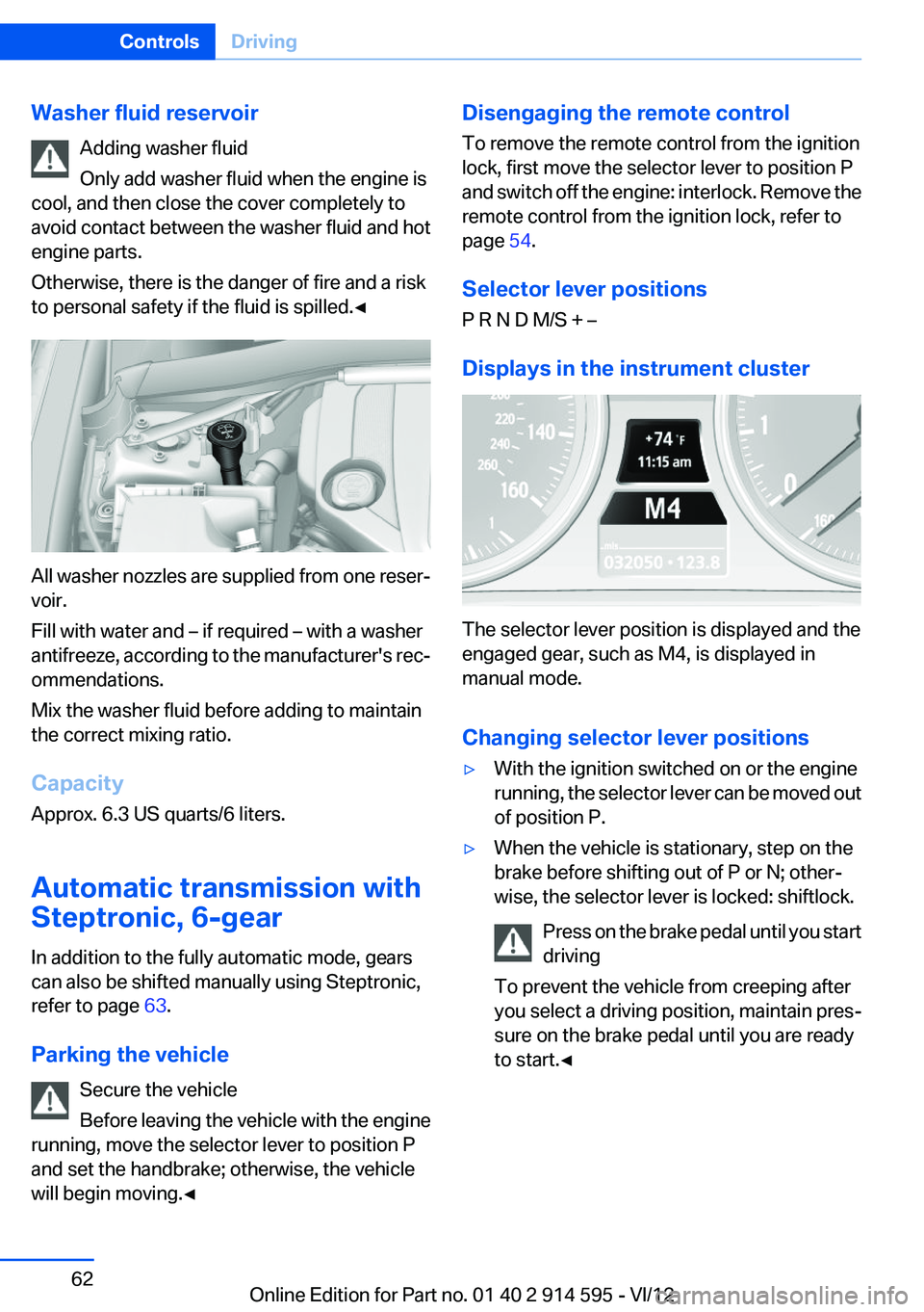
Washer fluid reservoirAdding washer fluid
Only add washer fluid when the engine is
cool, and then close the cover completely to
avoid contact between the washer fluid and hot
engine parts.
Otherwise, there is the danger of fire and a risk
to personal safety if the fluid is spilled.◀
All washer nozzles are supplied from one reser‐
voir.
Fill with water and – if required – with a washer
antifreeze, according to the manufacturer's rec‐
ommendations.
Mix the washer fluid before adding to maintain
the correct mixing ratio.
Capacity
Approx. 6.3 US quarts/6 liters.
Automatic transmission with
Steptronic, 6-gear
In addition to the fully automatic mode, gears
can also be shifted manually using Steptronic,
refer to page 63.
Parking the vehicle Secure the vehicle
Before leaving the vehicle with the engine
running, move the selector lever to position P
and set the handbrake; otherwise, the vehicle
will begin moving.◀
Disengaging the remote control
To remove the remote control from the ignition
lock, first move the selector lever to position P
and switch off the engine: interlock. Remove the
remote control from the ignition lock, refer to
page 54.
Selector lever positions
P R N D M/S + –
Displays in the instrument cluster
The selector lever position is displayed and the
engaged gear, such as M4, is displayed in
manual mode.
Changing selector lever positions
▷With the ignition switched on or the engine
running, the selector lever can be moved out
of position P.▷When the vehicle is stationary, step on the
brake before shifting out of P or N; other‐
wise, the selector lever is locked: shiftlock.
Press on the brake pedal until you start
driving
To prevent the vehicle from creeping after
you select a driving position, maintain pres‐
sure on the brake pedal until you are ready
to start.◀Seite 62ControlsDriving62
Online Edition for Part no. 01 40 2 914 595 - VI/12
Page 64 of 291
Shifting gears using the shift paddles
on the steering wheel
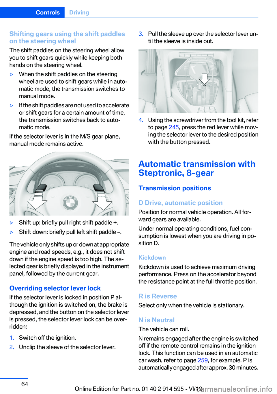
The shift paddles on the steering wheel allow
you to shift gears quickly while keeping both
hands on the steering wheel.▷When the shift paddles on the steering
wheel are used to shift gears while in auto‐
matic mode, the transmission switches to
manual mode.▷If the shift paddles are not used to accelerate
or shift gears for a certain amount of time,
the transmission switches back to auto‐
matic mode.
If the selector lever is in the M/S gear plane,
manual mode remains active.
▷Shift up: briefly pull right shift paddle +.▷Shift down: briefly pull left shift paddle –.
The vehicle only shifts up or down at appropriate
engine and road speeds, e.g., it does not shift
down if the engine speed is too high. The se‐
lected gear is briefly displayed in the instrument
panel, followed by the current gear.
Overriding selector lever lock
If the selector lever is locked in position P al‐
though the ignition is switched on, the brake is
depressed, and the button on the selector lever
is pressed, the selector lever lock can be over‐
ridden:
1.Switch off the ignition.2.Unclip the sleeve of the selector lever.3.Pull the sleeve up over the selector lever un‐
til the sleeve is inside out.4.Using the screwdriver from the tool kit, refer
to page 245, press the red lever while mov‐
ing the selector lever to the desired position
with the button pressed.
Automatic transmission with
Steptronic, 8-gear
Transmission positions
D Drive, automatic position
Position for normal vehicle operation. All for‐
ward gears are available.
Under normal operating conditions, fuel con‐
sumption is lowest when you are driving in po‐
sition D.
Kickdown
Kickdown is used to achieve maximum driving
performance. Press on the accelerator beyond
the resistance point at the full throttle position.
R is Reverse
Select only when the vehicle is stationary.
N is Neutral
The vehicle can roll.
N remains engaged after the engine is switched
off if the remote control remains in the ignition
lock. This function can be used in an automatic
car wash, refer to page 259, for example. P is
automatically engaged after approx. 30 minutes.
Seite 64ControlsDriving64
Online Edition for Part no. 01 40 2 914 595 - VI/12
Page 65 of 291
P Park
The drive wheels are blocked.
P is engaged automatically when the following
conditions are met:▷The driver's door is opened while the engine
is running, the safety belt is not fastened and
neither the brake pedal nor the accelerator
is activated.▷The engine is switched off unless N is en‐
gaged and the remote control is in the igni‐
tion lock.▷The remote control is removed from the ig‐
nition lock.
Before leaving the vehicle, ensure that the trans‐
mission position P is engaged; otherwise, the
vehicle may begin to roll.
Engaging transmission position
▷Transmission position P can only be disen‐
gaged if the engine is running and the brake
pedal is pressed.▷With the vehicle stationary, press on the
brake pedal before shifting out of P or N;
otherwise, the shift command will not be
executed: shift lock.
Press on the brake pedal until you start
driving
To prevent the vehicle from creeping after you
select a driving position, maintain pressure on
the brake pedal until you are ready to start.◀
Engaging transmission positions D, R,
N
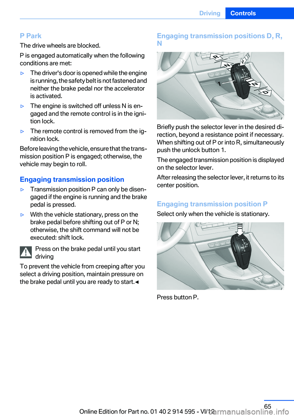
Briefly push the selector lever in the desired di‐
rection, beyond a resistance point if necessary.
When shifting out of P or into R, simultaneously
push the unlock button 1.
The engaged transmission position is displayed
on the selector lever.
After releasing the selector lever, it returns to its
center position.
Engaging transmission position P
Select only when the vehicle is stationary.
Press button P.
Seite 65DrivingControls65
Online Edition for Part no. 01 40 2 914 595 - VI/12
Page 76 of 291
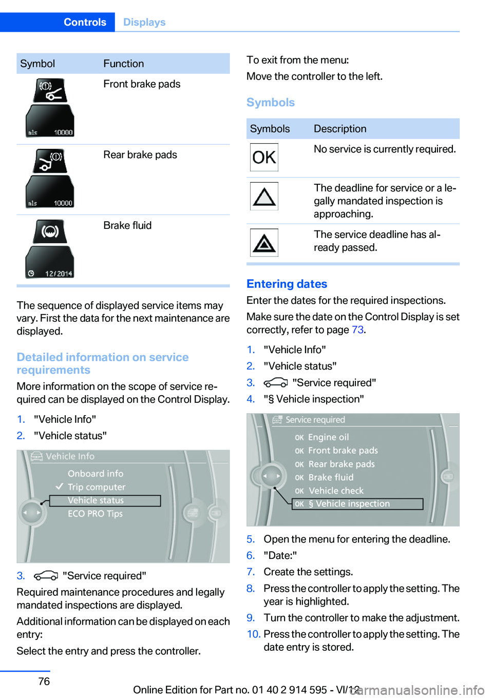
SymbolFunctionFront brake padsRear brake padsBrake fluid
The sequence of displayed service items may
vary. First the data for the next maintenance are
displayed.
Detailed information on service
requirements
More information on the scope of service re‐
quired can be displayed on the Control Display.
1."Vehicle Info"2."Vehicle status"3. "Service required"
Required maintenance procedures and legally
mandated inspections are displayed.
Additional information can be displayed on each
entry:
Select the entry and press the controller.
To exit from the menu:
Move the controller to the left.
SymbolsSymbolsDescriptionNo service is currently required.The deadline for service or a le‐
gally mandated inspection is
approaching.The service deadline has al‐
ready passed.
Entering dates
Enter the dates for the required inspections.
Make sure the date on the Control Display is set
correctly, refer to page 73.
1."Vehicle Info"2."Vehicle status"3. "Service required"4."§ Vehicle inspection"5.Open the menu for entering the deadline.6."Date:"7.Create the settings.8.Press the controller to apply the setting. The
year is highlighted.9.Turn the controller to make the adjustment.10.Press the controller to apply the setting. The
date entry is stored.Seite 76ControlsDisplays76
Online Edition for Part no. 01 40 2 914 595 - VI/12
Page 93 of 291

Please note that the TPMS is not a substitute for
proper tire maintenance, and it is the driver's re‐
sponsibility to maintain correct tire pressure,
even if under-inflation has not reached the level
to trigger illumination of the TPMS low tire pres‐
sure telltale.
Your vehicle has also been equipped with a
TPMS malfunction indicator to indicate when
the system is not operating properly. The TPMS
malfunction indicator is combined with the low
tire pressure telltale. When the system detects
a malfunction, the telltale will flash for approxi‐
mately one minute and then remain continu‐
ously illuminated. This sequence will continue
upon subsequent vehicle startups as long as the
malfunction exists. When the malfunction indi‐
cator is illuminated, the system may not be able
to detect or signal low tire pressure as intended.
TPMS malfunctions may occur for a variety of
reasons, including the installation of replace‐
ment or alternate tires or wheels on the vehicle
that prevent the TPMS from functioning prop‐
erly. Always check the TPMS malfunction tell‐
tale after replacing one or more tires or wheels
on your vehicle to ensure that the replacement
or alternate tires and wheels allow the TPMS to
continue to function properly.
Brake force display
The concept▷During normal brake application, the outer
brake lamps light up.▷During heavy brake application, the inner
brake lamps light up in addition.Seite 93SafetyControls93
Online Edition for Part no. 01 40 2 914 595 - VI/12
Page 94 of 291
Driving stability control systemsVehicle equipment
This chapter describes all series equipment as
well as country-specific and special equipment
offered for this model series.Therefore, it also
describes equipment that may not be found in
your vehicle, for instance due to the selected
special equipment or the country version. This
also applies to safety-related functions and sys‐
tems.
Antilock Brake System ABS
ABS prevents locking of the wheels during brak‐
ing.
The vehicle remains steerable even during full
brake applications, thus increasing active
safety.
ABS is operational every time you start the en‐
gine.
Electronic brake-force
distribution
The system controls the brake pressure in the
rear wheels to ensure stable braking behavior.
Brake assistant
When you apply the brakes rapidly, this system
automatically produces the maximum braking
force boost. It thus helps to achieve the shortest
possible braking distance during full braking.
This system utilizes all of the benefits provided
by ABS.
Do not reduce the pressure on the brake pedal
for the duration of the full braking.Dynamic Stability Control
DSC
The concept
DSC prevents traction loss in the driving wheels
when driving away and accelerating.
DSC also recognizes unstable vehicle condi‐
tions, such as fishtailing or nose-diving. Subject
to physical limits, DSC helps to keep the vehicle
on a steady course by reducing engine speed
and by applying brakes to the individual wheels.
Adjust your driving style to the situation
An appropriate driving style is always the
responsibility of the driver.
The laws of physics cannot be repealed, even
with DSC.
Do not reduce the additional safety margin with
a risky driving style, as otherwise there is a risk
of an accident.◀
Deactivating DSC: DSC OFF
When DSC is deactivated, driving stability is re‐
duced during acceleration and when driving in
bends.
To increase vehicle stability, activate DSC again
as soon as possible.
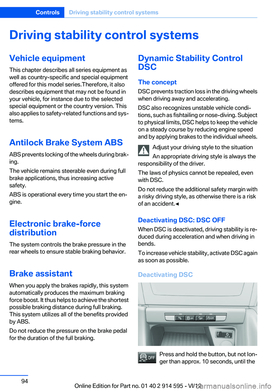
Deactivating DSC
Press and hold the button, but not lon‐
ger than approx. 10 seconds, until the
Seite 94ControlsDriving stability control systems94
Online Edition for Part no. 01 40 2 914 595 - VI/12
Page 95 of 291
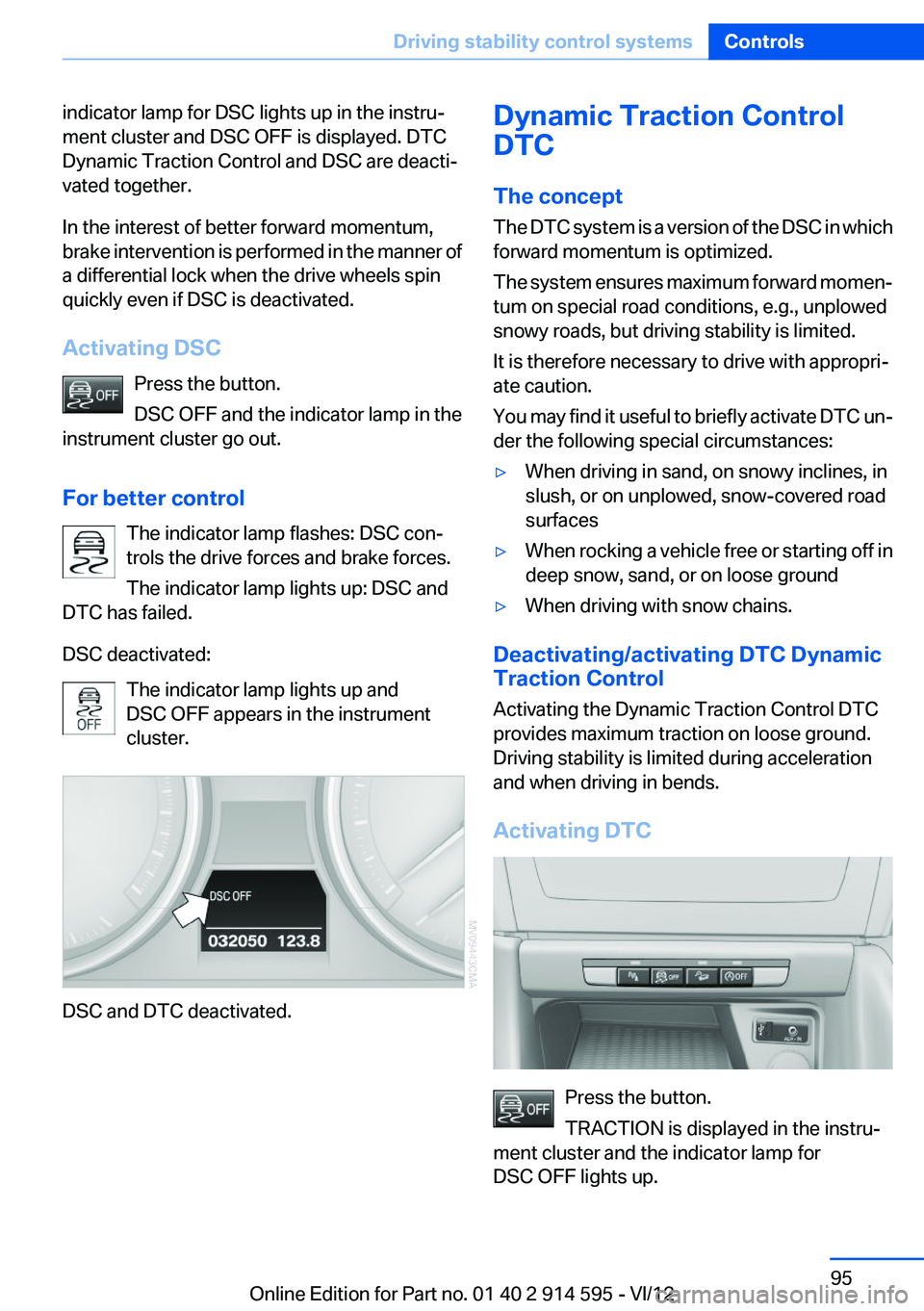
indicator lamp for DSC lights up in the instru‐
ment cluster and DSC OFF is displayed. DTC
Dynamic Traction Control and DSC are deacti‐
vated together.
In the interest of better forward momentum,
brake intervention is performed in the manner of
a differential lock when the drive wheels spin
quickly even if DSC is deactivated.
Activating DSC Press the button.
DSC OFF and the indicator lamp in the
instrument cluster go out.
For better control The indicator lamp flashes: DSC con‐
trols the drive forces and brake forces.
The indicator lamp lights up: DSC and
DTC has failed.
DSC deactivated: The indicator lamp lights up and
DSC OFF appears in the instrument
cluster.
DSC and DTC deactivated.
Dynamic Traction Control
DTC
The concept
The DTC system is a version of the DSC in which
forward momentum is optimized.
The system ensures maximum forward momen‐
tum on special road conditions, e.g., unplowed
snowy roads, but driving stability is limited.
It is therefore necessary to drive with appropri‐
ate caution.
You may find it useful to briefly activate DTC un‐
der the following special circumstances:▷When driving in sand, on snowy inclines, in
slush, or on unplowed, snow-covered road
surfaces▷When rocking a vehicle free or starting off in
deep snow, sand, or on loose ground▷When driving with snow chains.
Deactivating/activating DTC Dynamic
Traction Control
Activating the Dynamic Traction Control DTC
provides maximum traction on loose ground.
Driving stability is limited during acceleration
and when driving in bends.
Activating DTC
Press the button.
TRACTION is displayed in the instru‐
ment cluster and the indicator lamp for
DSC OFF lights up.
Seite 95Driving stability control systemsControls95
Online Edition for Part no. 01 40 2 914 595 - VI/12