2013 BMW X1 XDRIVE 28I turn signal
[x] Cancel search: turn signalPage 163 of 291
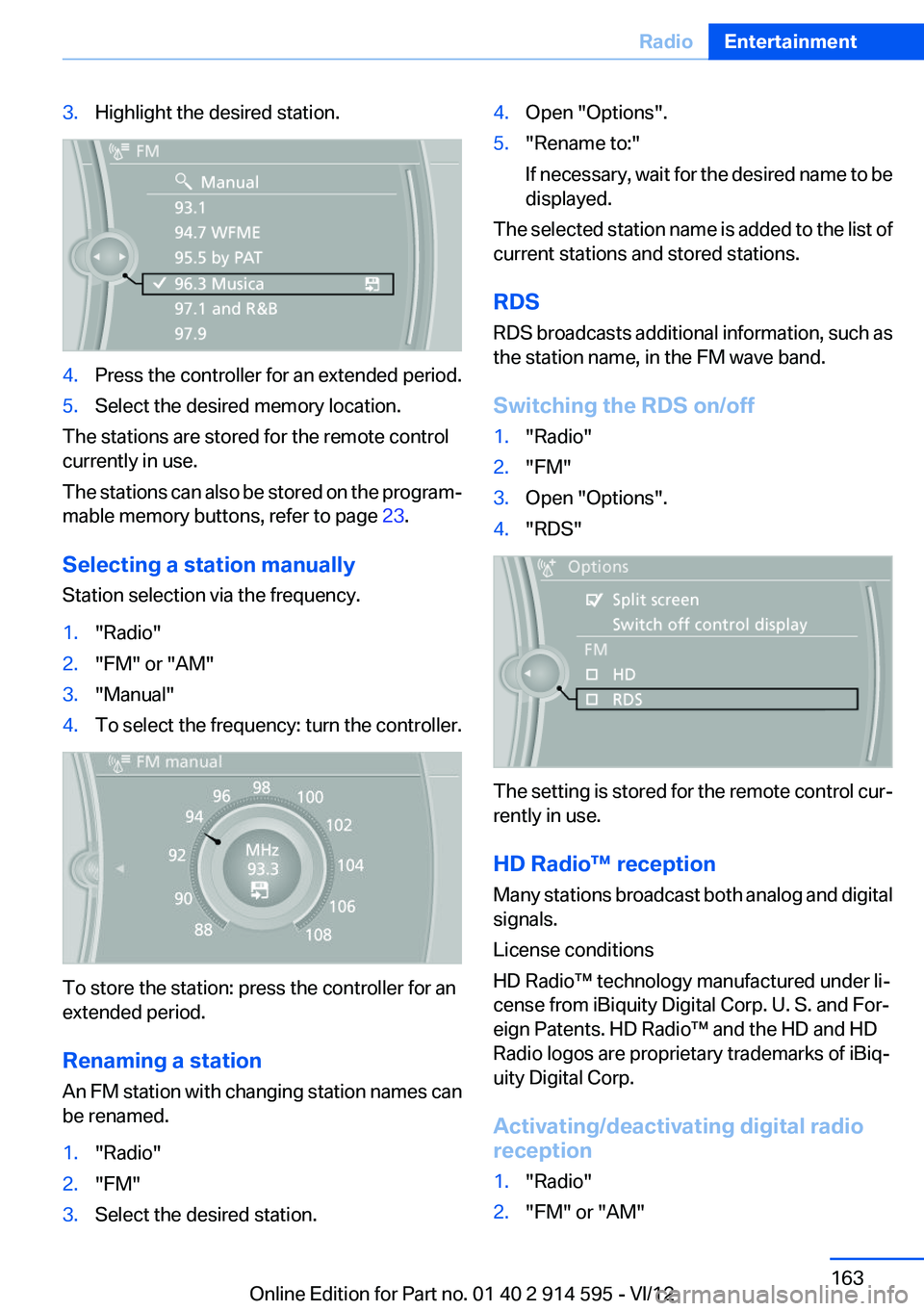
3.Highlight the desired station.4.Press the controller for an extended period.5.Select the desired memory location.
The stations are stored for the remote control
currently in use.
The stations can also be stored on the program‐
mable memory buttons, refer to page 23.
Selecting a station manually
Station selection via the frequency.
1."Radio"2."FM" or "AM"3."Manual"4.To select the frequency: turn the controller.
To store the station: press the controller for an
extended period.
Renaming a station
An FM station with changing station names can
be renamed.
1."Radio"2."FM"3.Select the desired station.4.Open "Options".5."Rename to:"
If necessary, wait for the desired name to be
displayed.
The selected station name is added to the list of
current stations and stored stations.
RDS
RDS broadcasts additional information, such as
the station name, in the FM wave band.
Switching the RDS on/off
1."Radio"2."FM"3.Open "Options".4."RDS"
The setting is stored for the remote control cur‐
rently in use.
HD Radio™ reception
Many stations broadcast both analog and digital
signals.
License conditions
HD Radio™ technology manufactured under li‐
cense from iBiquity Digital Corp. U. S. and For‐
eign Patents. HD Radio™ and the HD and HD
Radio logos are proprietary trademarks of iBiq‐
uity Digital Corp.
Activating/deactivating digital radio
reception
1."Radio"2."FM" or "AM"Seite 163RadioEntertainment163
Online Edition for Part no. 01 40 2 914 595 - VI/12
Page 196 of 291
▷Is the ambient temperature too high or low?
Do not expose the mobile phone to extreme
environmental conditions.
The telephone functions are not available.
▷Is the mobile phone paired as an additional
telephone and is the additional telephone
function deactivated? Activate the function.▷Is an outgoing call not possible? Connect
the mobile phone as a telephone.
No phone book entries or only some phone book
entries are displayed, or they are incomplete.
▷Transmission of the phone book entries is
not yet complete.▷It is possible that only the phone book en‐
tries of the mobile phone or the SIM card are
transmitted.▷It may not be possible to display phone book
entries with special characters.▷The number of phone book entries to be
stored is too high.▷Is the data volume of the contact too large,
e. g., due to stored information such as
notes? Reduce the data volume of the con‐
tact.▷Is the mobile phone connected as an audio
source or additional telephone? The mobile
phone must be connected as a telephone.
The phone connection quality is poor.
▷The strength of the Bluetooth signal on the
mobile phone can be adjusted, depending
on the mobile phone.▷Insert the mobile phone into the snap-in
adapter or place it in the area of the center
console.▷Adjust the volume of the microphone and
loudspeakers separately.
If all points in this list have been checked and the
required function is still not available, contact
Customer Relations or the service center.
Controls
Adjusting the volume
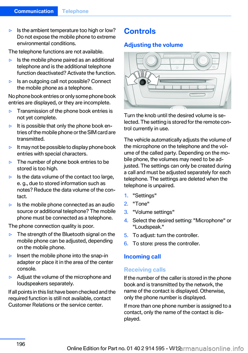
Turn the knob until the desired volume is se‐
lected. The setting is stored for the remote con‐
trol currently in use.
The vehicle automatically adjusts the volume of
the microphone on the telephone and the vol‐
ume of the called party. Depending on the mo‐
bile phone, the volumes may need to be ad‐
justed. The settings can only be created during
a call and must be adjusted separately for each
telephone. The settings are deleted when the
telephone is unpaired.
1."Settings"2."Tone"3."Volume settings"4.Select the desired setting: "Microphone" or
"Loudspeak."5.To adjust: turn the controller.6.To store: press the controller.
Incoming call
Receiving calls
If the number of the caller is stored in the phone
book and is transmitted by the network, the
name of the contact is displayed. Otherwise,
only the phone number is displayed.
If more than one phone number is assigned to a
contact, only the name of the contact is dis‐
played.
Seite 196CommunicationTelephone196
Online Edition for Part no. 01 40 2 914 595 - VI/12
Page 247 of 291
Removing the headlamp cover
The high beam bulbs can be replaced via the
engine compartment, and the low beam and turn
signal bulbs can be replaced via a folding cover
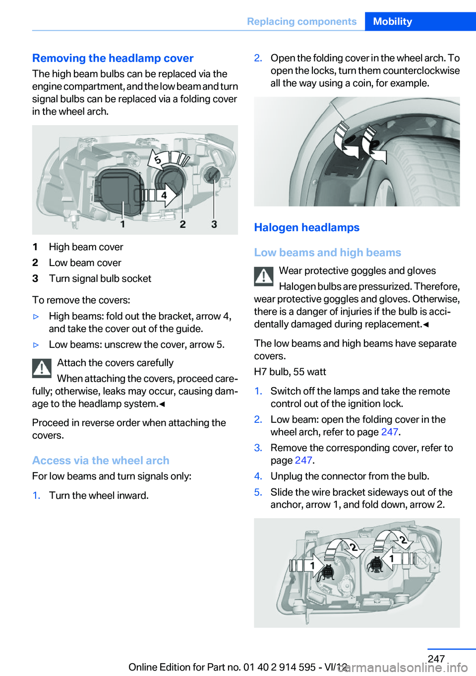
in the wheel arch.1High beam cover2Low beam cover3Turn signal bulb socket
To remove the covers:
▷High beams: fold out the bracket, arrow 4,
and take the cover out of the guide.▷Low beams: unscrew the cover, arrow 5.
Attach the covers carefully
When attaching the covers, proceed care‐
fully; otherwise, leaks may occur, causing dam‐
age to the headlamp system.◀
Proceed in reverse order when attaching the
covers.
Access via the wheel arch
For low beams and turn signals only:
1.Turn the wheel inward.2.Open the folding cover in the wheel arch. To
open the locks, turn them counterclockwise
all the way using a coin, for example.
Halogen headlamps
Low beams and high beams Wear protective goggles and gloves
Halogen bulbs are pressurized. Therefore,
wear protective goggles and gloves. Otherwise,
there is a danger of injuries if the bulb is acci‐
dentally damaged during replacement.◀
The low beams and high beams have separate
covers.
H7 bulb, 55 watt
1.Switch off the lamps and take the remote
control out of the ignition lock.2.Low beam: open the folding cover in the
wheel arch, refer to page 247.3.Remove the corresponding cover, refer to
page 247.4.Unplug the connector from the bulb.5.Slide the wire bracket sideways out of the
anchor, arrow 1, and fold down, arrow 2.Seite 247Replacing componentsMobility247
Online Edition for Part no. 01 40 2 914 595 - VI/12
Page 249 of 291
Turn signals, front
21-watt bulb, PY21W1.Switch off the lamps and take the remote
control out of the ignition lock.2.Open the folding cover in the wheel arch, re‐
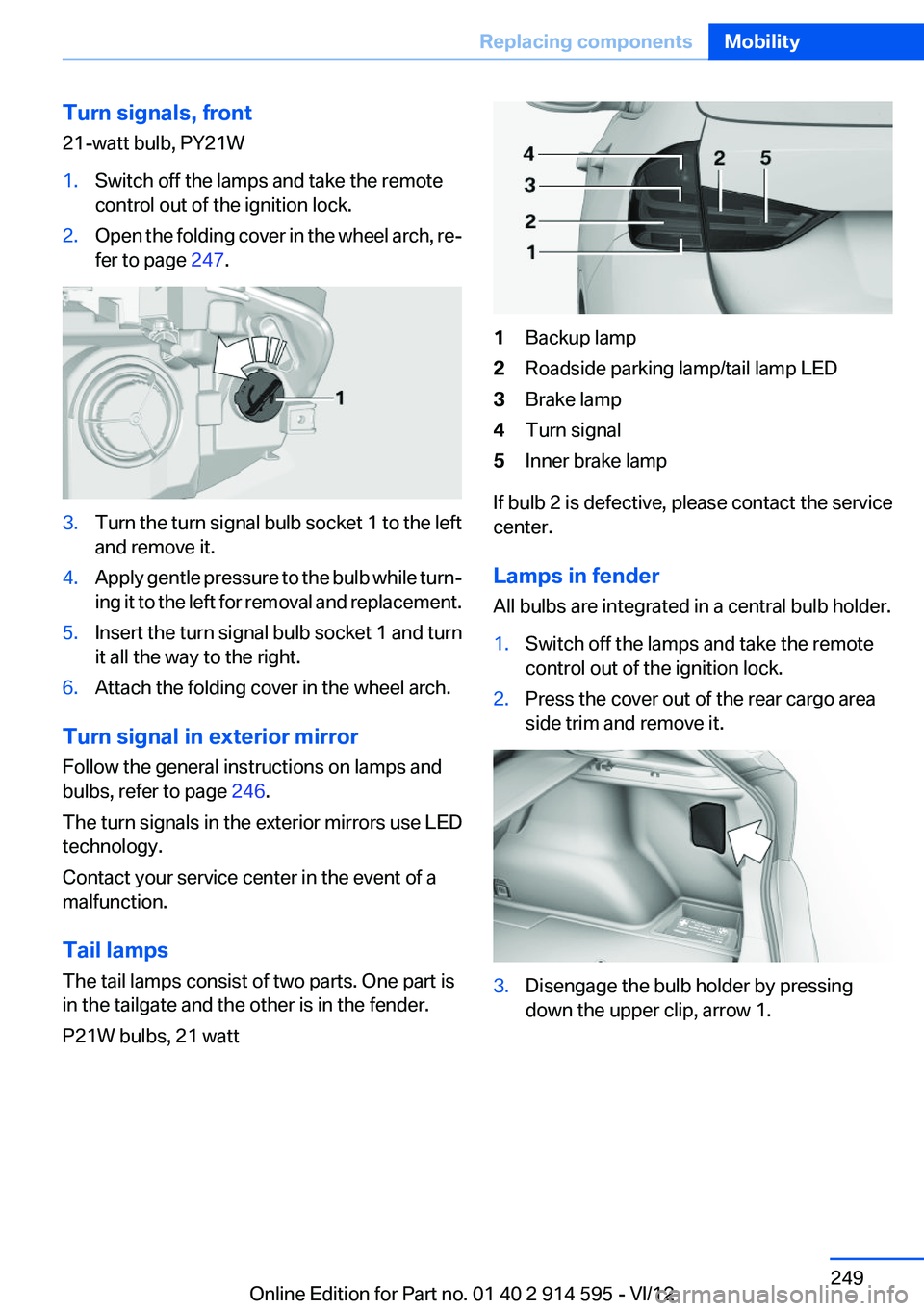
fer to page 247.3.Turn the turn signal bulb socket 1 to the left
and remove it.4.Apply gentle pressure to the bulb while turn‐
ing it to the left for removal and replacement.5.Insert the turn signal bulb socket 1 and turn
it all the way to the right.6.Attach the folding cover in the wheel arch.
Turn signal in exterior mirror
Follow the general instructions on lamps and
bulbs, refer to page 246.
The turn signals in the exterior mirrors use LED
technology.
Contact your service center in the event of a
malfunction.
Tail lamps
The tail lamps consist of two parts. One part is
in the tailgate and the other is in the fender.
P21W bulbs, 21 watt
1Backup lamp2Roadside parking lamp/tail lamp LED3Brake lamp4Turn signal5Inner brake lamp
If bulb 2 is defective, please contact the service
center.
Lamps in fender
All bulbs are integrated in a central bulb holder.
1.Switch off the lamps and take the remote
control out of the ignition lock.2.Press the cover out of the rear cargo area
side trim and remove it.3.Disengage the bulb holder by pressing
down the upper clip, arrow 1.Seite 249Replacing componentsMobility249
Online Edition for Part no. 01 40 2 914 595 - VI/12
Page 253 of 291
Breakdown assistanceVehicle equipment
This chapter describes all series equipment as
well as country-specific and special equipment
offered for this model series.Therefore, it also
describes equipment that may not be found in
your vehicle, for instance due to the selected
special equipment or the country version. This
also applies to safety-related functions and sys‐
tems.
Hazard warning flashers
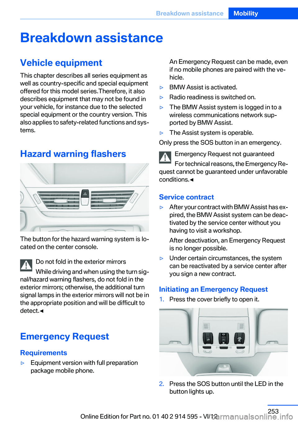
The button for the hazard warning system is lo‐
cated on the center console.
Do not fold in the exterior mirrors
While driving and when using the turn sig‐
nal/hazard warning flashers, do not fold in the
exterior mirrors; otherwise, the additional turn
signal lamps in the exterior mirrors will not be in
the appropriate position and will be difficult to
detect.◀
Emergency Request
Requirements
▷Equipment version with full preparation
package mobile phone.An Emergency Request can be made, even
if no mobile phones are paired with the ve‐
hicle.▷BMW Assist is activated.▷Radio readiness is switched on.▷The BMW Assist system is logged in to a
wireless communications network sup‐
ported by BMW Assist.▷The Assist system is operable.
Only press the SOS button in an emergency.
Emergency Request not guaranteed
For technical reasons, the Emergency Re‐
quest cannot be guaranteed under unfavorable
conditions.◀
Service contract
▷After your contract with BMW Assist has ex‐
pired, the BMW Assist system can be deac‐
tivated by the service center without you
having to visit a workshop.
After deactivation, an Emergency Request
is no longer possible.▷Under certain circumstances, the system
can be reactivated by a service center after
you sign a new contract.
Initiating an Emergency Request
1.Press the cover briefly to open it.2.Press the SOS button until the LED in the
button lights up.Seite 253Breakdown assistanceMobility253
Online Edition for Part no. 01 40 2 914 595 - VI/12
Page 257 of 291
Being towedFollow the towing instructions
Follow all towing instructions, or vehicle
damage or accidents may occur.◀▷Make sure that the ignition is switched on;
otherwise, the low beams, tail lamps, turn
signals, and windshield wipers may be un‐
available.▷Do not tow the vehicle with the rear axle
tilted, as the front wheels could turn.▷When the engine is stopped, there is no
power assist. Consequently, more force
needs to be applied when braking and steer‐
ing.▷Larger steering wheel movements are re‐
quired.▷Switch on the hazard warning system, de‐
pending on local regulations.▷If the electrical system has failed, clearly
identify the vehicle being towed by placing
a sign or a warning triangle in the rear win‐
dow.
Towing other vehicles
General information Light towing vehicle
Your vehicle must not be lighter than the
vehicle being towed; otherwise, it will not be
possible to control vehicle response.◀
Attaching the tow bar/tow rope correctly
Attach the tow bar or tow rope to the tow
fitting; connecting it to other vehicle parts may
cause damage.◀
▷Switch on the hazard warning system, de‐
pending on local regulations.▷If the electrical system has failed, clearly
identify the vehicle being towed by placing
a sign or a warning triangle in the rear win‐
dow.Towing methods
Do not lift the vehicle
Do not lift the vehicle by the tow fitting or
body and chassis parts; otherwise, damage may
result.◀
Tow bar
The tow fittings used should be on the same
side on both vehicles.
Should it prove impossible to avoid mounting
the tow bar at an offset angle, please observe
the following:▷Clearance and maneuvering capability will
be sharply limited during cornering.▷The tow bar will generate lateral forces if it
is attached offset.
Tow rope
When starting to tow the vehicle, make sure that
the tow rope is taut.
To avoid jerking and the associated stresses on
the vehicle components when towing, always
use nylon ropes or nylon straps.
Attaching the tow rope correctly
Only secure the tow rope on the tow fit‐
ting; otherwise, damage can occur when it is se‐
cured on other parts of the vehicle.◀
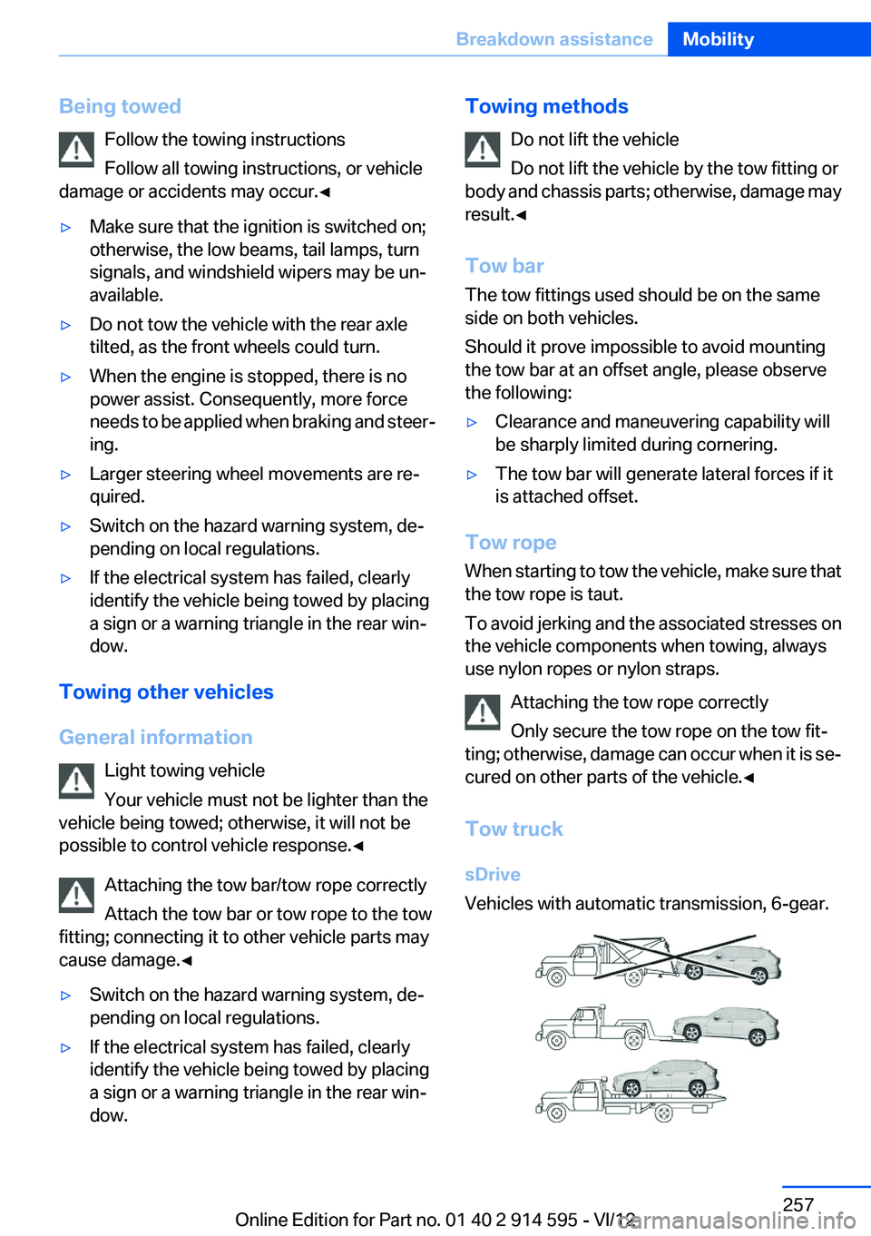
Tow truck
sDrive
Vehicles with automatic transmission, 6-gear.
Seite 257Breakdown assistanceMobility257
Online Edition for Part no. 01 40 2 914 595 - VI/12
Page 278 of 291

Carpet, care 261
Car phone, installation loca‐ tion, refer to Center arm‐
rest 120
Car phone, refer to Tele‐ phone 192
Car vacuum cleaner, connect‐ ing, refer to Connecting elec‐
trical devices 114
Car wash 259
Catalytic converter, refer to Hot exhaust system 126
CBS Condition Based Serv‐ ice 243
CD/DVD 170
CD/DVD notes 175
CD changer 174
CDs, storing 176
Cell phone 192
Cell phone, installation loca‐ tion, refer to Center arm‐
rest 120
Center armrest, front 120
Center armrest, rear 121
Center brake lamp, bulb re‐ placement 250
Center console, refer to Around the center con‐
sole 16
Central locking– Comfort Access 36– From the inside 34– Setting the unlocking char‐
acteristics 32
Central locking system
– From the outside 31– Principle 31
Central screen, refer to Control
Display 18
Changes, technical, refer to Safety 6
Changing wheels/tires 235
Check Control 77
Children, transporting 50
Child restraint fixing system LATCH 51
Child restraint fixing sys‐
tems 50
Child restraint fixing systems, mounting 50
Child safety locks 53
Child seat, mounting 50
Child seats, refer to Transport‐ ing children safely 50
Chrome parts, care 261
Cigarette lighter, connecting electrical devices 114
Cigarette lighter, refer to Lighter 114
Cigarette lighter socket 114
Circulation of air, refer to Re‐ circulated air mode 107
Cleaning, displays 262
Cleaning your BMW, refer to Care 259
Clock 68
Clock– 12h/24h format 73– Setting the time and date 73
Closing
– From the inside 34– From the outside 32
Clothes hooks 122
Cockpit 12
Cold start, refer to Starting the engine 55
Combination instrument, refer to Instrument cluster 14
Combination switch, refer to Turn signal/high beams/
headlamp flasher 59
Combination switch, refer to Washer/wiper system 59
Comfort Access
– Battery replacement 38
Comfort area, refer to Around
the center console 16
Compact wheel, inflation pres‐ sure 228
Compartment for remote con‐ trol, refer to Ignition lock 54
Compartment in floor 118
Compartments, refer to Stor‐
age compartments 120, 121
Compass, digital 112
Computer 70
Computer, displaying informa‐ tion 70
Computer, displays on the Control Display 70
Concierge service 216
Condensation under the vehi‐ cle 128
Condition Based Service CBS 243
Confirmation signals for lock‐ ing/unlocking the vehicle 33
ConnectedDrive 215
Connecting, mobile phone, re‐ fer to Pairing the mobile
phone 193
Consumption, refer to Aver‐ age fuel consumption 70
Contacts 205, 213
Control Display 18
Control Display, care 262
Control Display, settings 74
Controller 19
Controls and displays 12
Control systems, driving sta‐ bility 94
Convenient operation– Glass sunroof 32– Window 32
Coolant 242
Coolant, checking the level 242
Coolant temperature 69
Cooling function, switching on and off 107
Cooling, maximum 106
Cooling system, refer to Cool‐ ant 242
Corrosion on brake discs 128
Courtesy lamps, refer to Inte‐ rior lamps 84
Cradle for telephone or mobile phone, refer to Snap-in
adapter 202
Seite 278ReferenceEverything from A to Z278
Online Edition for Part no. 01 40 2 914 595 - VI/12
Page 279 of 291

Cruise control 98
Cruise control– Malfunction 99
Cupholder 122
Curb weight, refer to Weights 267
Current fuel consumption 69
Current location, storing 142
Curve lights, refer to Adaptive light control 81
D
Dashboard lighting, refer to In‐ strument lighting 83
Dashboard, refer to Cock‐ pit 12
Data, technical 266
Date
– Date format 74– Setting 73
Daytime running lights 81
Daytime running lights, bulb replacement 248
Defroster
– Rear window 107
Destination entry via the ad‐
dress book 142
Destination guidance 149
Destination guidance with in‐ termediate destinations 147
Destination input, naviga‐ tion 140
Digital clock 68
Digital compass 112
Digital radio 163
Dimming mirrors 49
Directional indicators, refer to Turn signals 59
Display lighting, refer to Instru‐ ment lighting 83
Displays and controls 12
Displays, care 262
Displays, cleaning 262
Displays, refer to Instrument cluster 14
Disposal, coolant 242
Disposal, vehicle battery 251
Distance warning, refer to Park Distance Control PDC 100
Divided rear seat backrest, re‐ fer to Enlarging the cargo
area 115
Divided screen view, split screen 22
Door key, refer to Remote con‐ trol with integrated key 30
Door lock 34
Doors, manual operation 34
Doors, unlocking and locking– Confirmation signals 33– From the inside 34– From the outside 32
DOT Quality Grades 233
Downhill control 96
Draft-free ventilation 108
Drive-off assistant 97
Driving away on inclines, refer to Drive-off assistant 97
Driving notes, breaking in 126
Driving notes, general 126
Driving on poor roads 128
Driving stability control sys‐ tems 94
Driving through water 127
Driving tips, refer to Driving notes 126
Dry air, refer to Cooling func‐ tion 107
DSC Dynamic Stability Con‐ trol 94
DTC Dynamic Traction Con‐ trol 95
DTMF suffix dialing 198
DVD/CD 170
DVDs, storing 176
DVD, video 172
Dynamic destination guid‐ ance 156
Dynamic Stability Control DSC 94
Dynamic Traction Control DTC 95
E
ECO PRO 134
ECO PRO display 134
ECO PRO driving mode 134
ECO PRO mode 134
EfficientDynamics, refer to Saving fuel 133
Electrical malfunction– Door lock 34– Driver's door 34– Fuel filler flap 225– Tailgate 36
Electric seat adjustment 44
Electronic brake-force distri‐ bution 94
Electronic engine oil level check 239
Electronic Stability Program ESP, refer to Dynamic Stabil‐
ity Control DSC 94
Emergency activation
– Automatic transmission, re‐
fer to Overriding selector
lever lock 64
Emergency operation
– Door lock, refer to Manual
operation 34
Emergency operation, fuel
filler flap, unlocking man‐
ually 225
Emergency Request 253
Emergency service, refer to Roadside Assistance 254
Energy-conscious driving, re‐ fer to Current fuel consump‐
tion 69
Energy, saving
– Automatic Engine Start/Stop
Function 56
Energy, saving, refer to Saving
fuel 133
Engine, breaking in 126
Engine compartment 238
Engine coolant, refer to Cool‐ ant 242
Engine oil, adding 241
Seite 279Everything from A to ZReference279
Online Edition for Part no. 01 40 2 914 595 - VI/12