2013 BMW X1 XDRIVE 28I trailer
[x] Cancel search: trailerPage 39 of 291

Arming and disarming the alarm
system
General information
When you lock or unlock the vehicle, either with
the remote control or at the door lock, the alarm
system is armed or disarmed at the same time.
Door lock and armed alarm system
Unlocking via the door lock will trigger the alarm
on some market-specific versions.
To stop this alarm, unlock the vehicle with the
remote control or switch on the ignition.
Tailgate and armed alarm system
The tailgate can be opened using the remote
control, even if the alarm system is armed.
Press the button on the remote control.
After the tailgate is closed, it is locked and moni‐
tored again by the alarm system. The hazard
warning system flashes once.
In some market-specific versions, the tailgate
can only be opened using the remote control if
the vehicle was unlocked first.
Switching off the alarm
▷Unlock the vehicle using the remote control,
refer to page 32.▷Insert the remote control all the way into the
ignition lock.
Indicator lamp on the interior rearview
mirror
▷The indicator lamp flashes briefly every
2 seconds:
The system is armed.▷The indicator lamp flashes after locking:
The doors, hood or tailgate is not closed
properly, but the rest of the vehicle is se‐
cured.
The indicator lamp flashes continuously af‐
ter approx. 10 seconds. The interior motion
sensor is not active.▷The indicator lamp goes out after unlocking:
The vehicle has not been tampered with.▷If the indicator lamp flashes after unlocking
until the remote control is inserted in the ig‐
nition, but for no longer than approx. 5 mi‐
nutes:
An alarm has been triggered.
Panic mode
In dangerous situations, trigger the alarm sys‐
tem:
Press the button on the remote control for at
least 3 seconds.
To switch off the alarm: press any button.
Tilt alarm sensor
The tilt of the vehicle is monitored.
The alarm system responds in situations such
as attempts to steal a wheel or tow the car.
Interior motion sensor
For the sensor to function properly, the windows
and panoramic glass sunroof must be closed.
Avoiding unintentional alarms
The tilt alarm sensor and interior motion sensor
can be switched off together, such as in the fol‐
lowing situations:
▷In duplex garages.▷During transport on car-carrying trains, at
sea or on a trailer.Seite 39Opening and closingControls39
Online Edition for Part no. 01 40 2 914 595 - VI/12
Page 100 of 291

Park Distance Control PDC
The concept
In addition to the PDC Park Distance Control, the
backup camera, refer to page 102, can be
switched on.
PDC supports you when parking. A slow ap‐
proach to an object in front of or behind your ve‐
hicle is announced by:▷Signal tones.▷Visual display.
Measurement
Measurements are made by ultrasound sensors
in the bumpers.
The range is approx. 6 ft/2 m.
An acoustic warning is first given:
▷By the front sensors and two rear corner
sensors at approx. 24 in/60 cm.▷By the rear middle sensors at approx.
5 ft/1.50 m.
System limits
Check the traffic situation as well
PDC cannot serve as a substitute for the
driver's personal judgment of the traffic situa‐
tion. Check the traffic situation around the vehi‐
cle with your own eyes. Otherwise, an accident
could result from road users or objects located
outside of the PDC detection range.
Loud noises from outside and inside the vehicle
may prevent you from hearing the PDC's signal
tone.◀
Avoid driving quickly with PDC
Avoid approaching an object quickly.
Avoid driving away quickly while PDC is not yet
active.
For technical reasons, the system may other‐
wise be too late in issuing a warning.◀
Limits of ultrasonic measurement
The detection of objects can reach the physical
limits of ultrasonic measurement, for instance:▷With tow bars and trailer hitches.▷With thin or wedge-shaped objects.▷With low objects.▷With objects with corners and sharp edges.
Low objects already displayed, e.g., curbs, can
move into the blind area of the sensors before or
after a continuous tone sounds.
High, protruding objects such as ledges may not
be detected.
False warnings
PDC may issue a warning under the following
conditions even though there is no obstacle
within the detection range:
▷In heavy rain.▷When sensors are very dirty or covered in
ice.▷When sensors are covered in snow.▷On rough road surfaces.▷In large buildings with right angles and
smooth walls, e.g., in underground garages.▷In heavy exhaust.▷Due to other ultrasound sources, e.g.,
sweeping machines, high pressure steam
cleaners or neon lights.
Switching on automatically
With the engine running or the ignition switched
on, shift the selector lever into position R.
Switching off automatically when
driving forward
The system switches off when a certain distance
or speed is exceeded.
Switch on the system again if necessary.
Seite 100ControlsDriving comfort100
Online Edition for Part no. 01 40 2 914 595 - VI/12
Page 130 of 291

LoadingVehicle equipment
This chapter describes all series equipment as
well as country-specific and special equipment
offered for this model series.Therefore, it also
describes equipment that may not be found in
your vehicle, for instance due to the selected
special equipment or the country version. This
also applies to safety-related functions and sys‐
tems.
General information Overloading the vehicle
To avoid exceeding the approved carrying
capacity of the tires, never overload the vehicle.
Overloading can lead to overheating and in‐
creases the rate at which damage develops in‐
side the tires. This could result in a sudden loss
of tire inflation pressure.◀
No fluids in the cargo area
Make sure that fluids do not leak into the
cargo area; otherwise, the vehicle may be dam‐
aged.◀
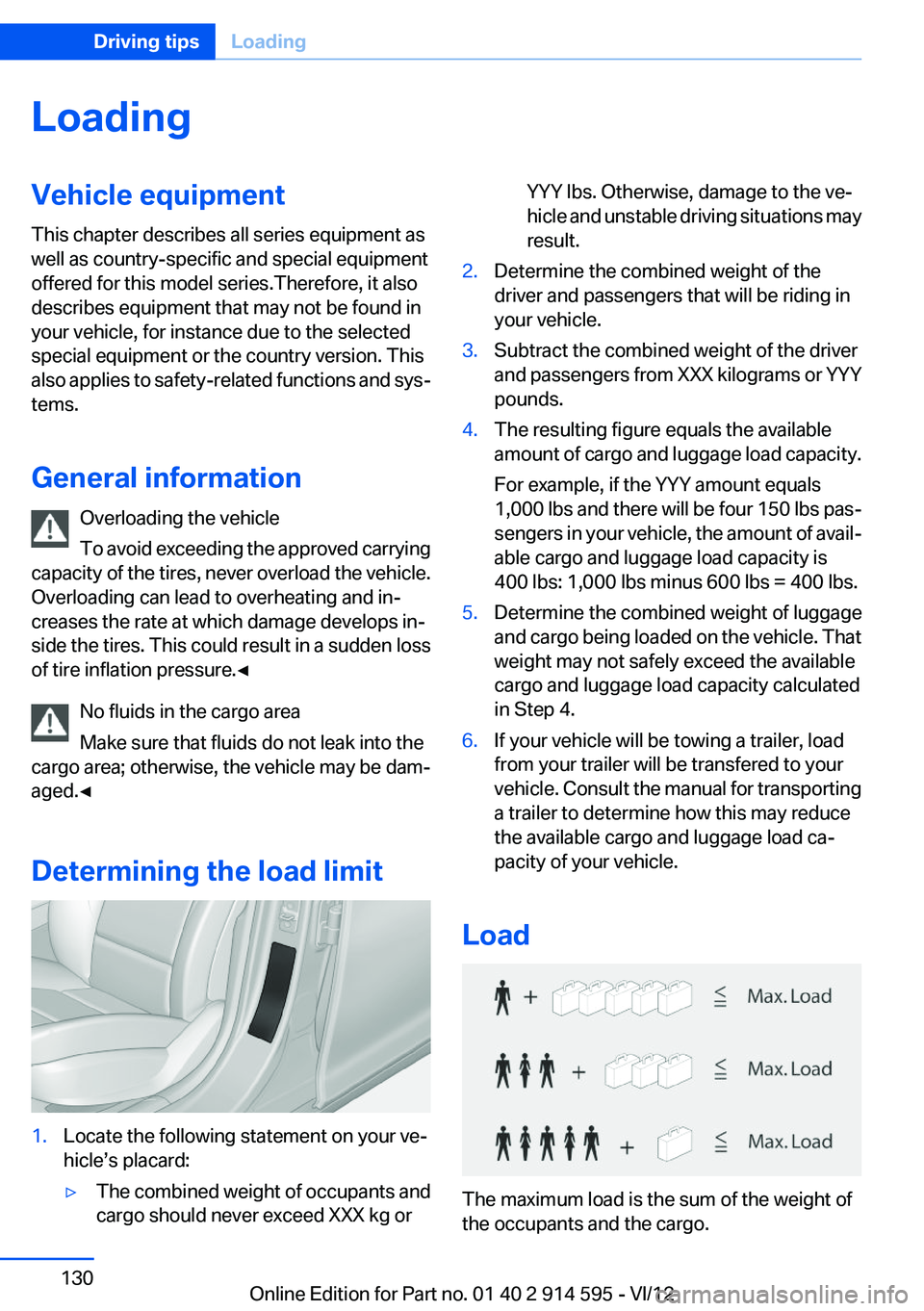
Determining the load limit1.Locate the following statement on your ve‐
hicle’s placard:▷The combined weight of occupants and
cargo should never exceed XXX kg orYYY lbs. Otherwise, damage to the ve‐
hicle and unstable driving situations may
result.2.Determine the combined weight of the
driver and passengers that will be riding in
your vehicle.3.Subtract the combined weight of the driver
and passengers from XXX kilograms or YYY
pounds.4.The resulting figure equals the available
amount of cargo and luggage load capacity.
For example, if the YYY amount equals
1,000 lbs and there will be four 150 lbs pas‐
sengers in your vehicle, the amount of avail‐
able cargo and luggage load capacity is
400 lbs: 1,000 lbs minus 600 lbs = 400 lbs.5.Determine the combined weight of luggage
and cargo being loaded on the vehicle. That
weight may not safely exceed the available
cargo and luggage load capacity calculated
in Step 4.6.If your vehicle will be towing a trailer, load
from your trailer will be transfered to your
vehicle. Consult the manual for transporting
a trailer to determine how this may reduce
the available cargo and luggage load ca‐
pacity of your vehicle.
Load
The maximum load is the sum of the weight of
the occupants and the cargo.
Seite 130Driving tipsLoading130
Online Edition for Part no. 01 40 2 914 595 - VI/12
Page 132 of 291

Roof-mounted luggage rack
Notes
A special rack system is available as an optional
accessory.
Anchorage points
The anchorage points are located on the roof
railing.
Attachment
Follow the installation instructions for the roof-
mounted luggage rack.
Be sure that adequate clearance is maintained
for tilting and opening the panoramic glass sun‐
roof.
Loading
Because roof racks raise the vehicle's center of
gravity when loaded, they have a major effect on
vehicle handling and steering response.
Therefore, note the following when loading and
driving:▷Do not exceed the approved roof/axle loads
and the approved gross vehicle weight.▷Distribute the roof load uniformly.▷The roof load should not be too large in area.▷Always load the heaviest pieces on the bot‐
tom.▷Fasten the roof-mounted luggage securely,
for instance using lashing straps.▷Do not let objects project into the opening
path of the tailgate.▷Drive smoothly. Avoid sudden acceleration
and braking maneuvers. Take corners gen‐
tly.Rear luggage rack
Notes
A special rear rack is available as an optional ac‐
cessory. It does not require a trailer hitch.
Follow the installation instructions for the rear
rack.
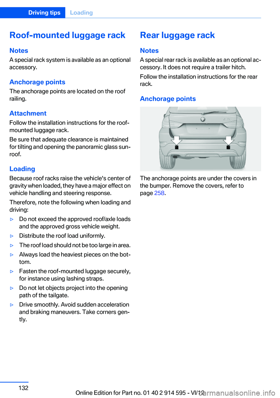
Anchorage points
The anchorage points are under the covers in
the bumper. Remove the covers, refer to
page 258.
Seite 132Driving tipsLoading132
Online Edition for Part no. 01 40 2 914 595 - VI/12