2013 BMW X1 XDRIVE 28I roof
[x] Cancel search: roofPage 122 of 291
Cargo area▷Retaining strap on the left side panel for se‐
curing small items.▷Retaining straps on the cargo area floor.▷Insertable partition elements for the storage
compartment under the cargo floor panel,
used to variably subdivide the storage com‐
partment.
With partition net: arrange the partition ele‐
ments in such a way that there is enough
space at the rear of the storage compart‐
ment for the partition net.▷Storage net next to the storage compart‐
ment on the right in the cargo area.
Clothes hooks
The clothes hooks are located at the grab han‐
dles in the rear.
Do not obstruct view
When suspending clothing from the
hooks, ensure that it will not obstruct the driver's
vision.◀
No heavy objects
Do not hang heavy objects from the hooks;
otherwise, they may present a danger to pas‐
sengers during braking and evasive maneu‐
vers.◀
Cupholders
Notes Shatter-proof containers and no hot
drinks
Use light and shatter-proof containers and do
not transport hot drinks. Otherwise, there is the
increased danger of injury in an accident.◀
Unsuitable containers
Do not forcefully push unsuitable contain‐
ers into the cupholders. This may result in dam‐
age.◀
Front▷In the front door compartments as a bottle
holder for 1-quart/1 liter bottles, for exam‐
ple.
Insert the bottle into the bottle holder with
the bottom slanted toward the front.▷In the center console.
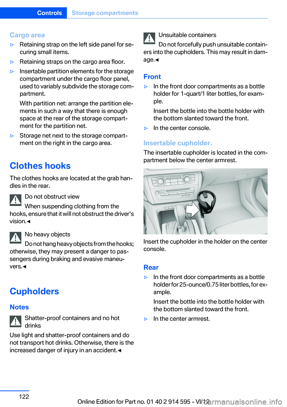
Insertable cupholder.
The insertable cupholder is located in the com‐
partment below the center armrest.
Insert the cupholder in the holder on the center
console.
Rear
▷In the front door compartments as a bottle
holder for 25-ounce/0.75 liter bottles, for ex‐
ample.
Insert the bottle into the bottle holder with
the bottom slanted toward the front.▷In the center armrest.Seite 122ControlsStorage compartments122
Online Edition for Part no. 01 40 2 914 595 - VI/12
Page 126 of 291
Things to remember when drivingVehicle equipment
This chapter describes all series equipment as
well as country-specific and special equipment
offered for this model series.Therefore, it also
describes equipment that may not be found in
your vehicle, for instance due to the selected
special equipment or the country version. This
also applies to safety-related functions and sys‐
tems.
Breaking-in period
General information
Moving parts need to be broken in to adjust to
each other.
The following instructions will help achieve a
long vehicle life and good economy.
Engine and differential
Always obey all official speed limits.
Up to 1,200 miles/2,000 km
Do not exceed the maximum engine and road
speeds:▷For a gasoline engine, 4,500 rpm and
100 mph/160 km/h.
Avoid full-throttle operation and use of the
transmission's kickdown mode for the initial
miles.
From 1,200 miles/2,000 km
The engine and vehicle speed can gradually be
increased.
Tires
Due to technical factors associated with their
manufacture, tires do not achieve their full trac‐
tion potential until after an initial breaking-in pe‐
riod.
Drive conservatively for the first
200 miles/300 km.
Brake system
Brakes require an initial break-in period of ap‐
prox. 300 miles/500 km to achieve optimized
contact and wear patterns between brake pads
and rotors. Drive cautiously during this break-in
period.
Following part replacement
The same breaking in procedures should be ob‐
served if any of the components mentioned
above have to be renewed in the course of the
vehicle's operating life.
General driving notes
Closing tailgate Drive with the tailgate closed
Only drive with the tailgate closed; other‐
wise, passengers and other road users may be
endangered or the vehicle may be damaged if an
accident occurs or during braking or evasive
maneuvers. In addition, exhaust fumes may en‐
ter the passenger compartment.◀
If, despite this, the vehicle must be driven with
the tailgate open:▷Drive moderately.▷Close all windows and the panoramic glass
sunroof.▷Greatly increase the blower speed.
Hot exhaust system
Hot exhaust system
High temperatures are generated in the
exhaust system.
Seite 126Driving tipsThings to remember when driving126
Online Edition for Part no. 01 40 2 914 595 - VI/12
Page 132 of 291
Roof-mounted luggage rack
Notes
A special rack system is available as an optional
accessory.
Anchorage points
The anchorage points are located on the roof
railing.
Attachment
Follow the installation instructions for the roof-
mounted luggage rack.
Be sure that adequate clearance is maintained
for tilting and opening the panoramic glass sun‐
roof.
Loading
Because roof racks raise the vehicle's center of
gravity when loaded, they have a major effect on
vehicle handling and steering response.
Therefore, note the following when loading and
driving:▷Do not exceed the approved roof/axle loads
and the approved gross vehicle weight.▷Distribute the roof load uniformly.▷The roof load should not be too large in area.▷Always load the heaviest pieces on the bot‐
tom.▷Fasten the roof-mounted luggage securely,
for instance using lashing straps.▷Do not let objects project into the opening
path of the tailgate.▷Drive smoothly. Avoid sudden acceleration
and braking maneuvers. Take corners gen‐
tly.Rear luggage rack
Notes
A special rear rack is available as an optional ac‐
cessory. It does not require a trailer hitch.
Follow the installation instructions for the rear
rack.
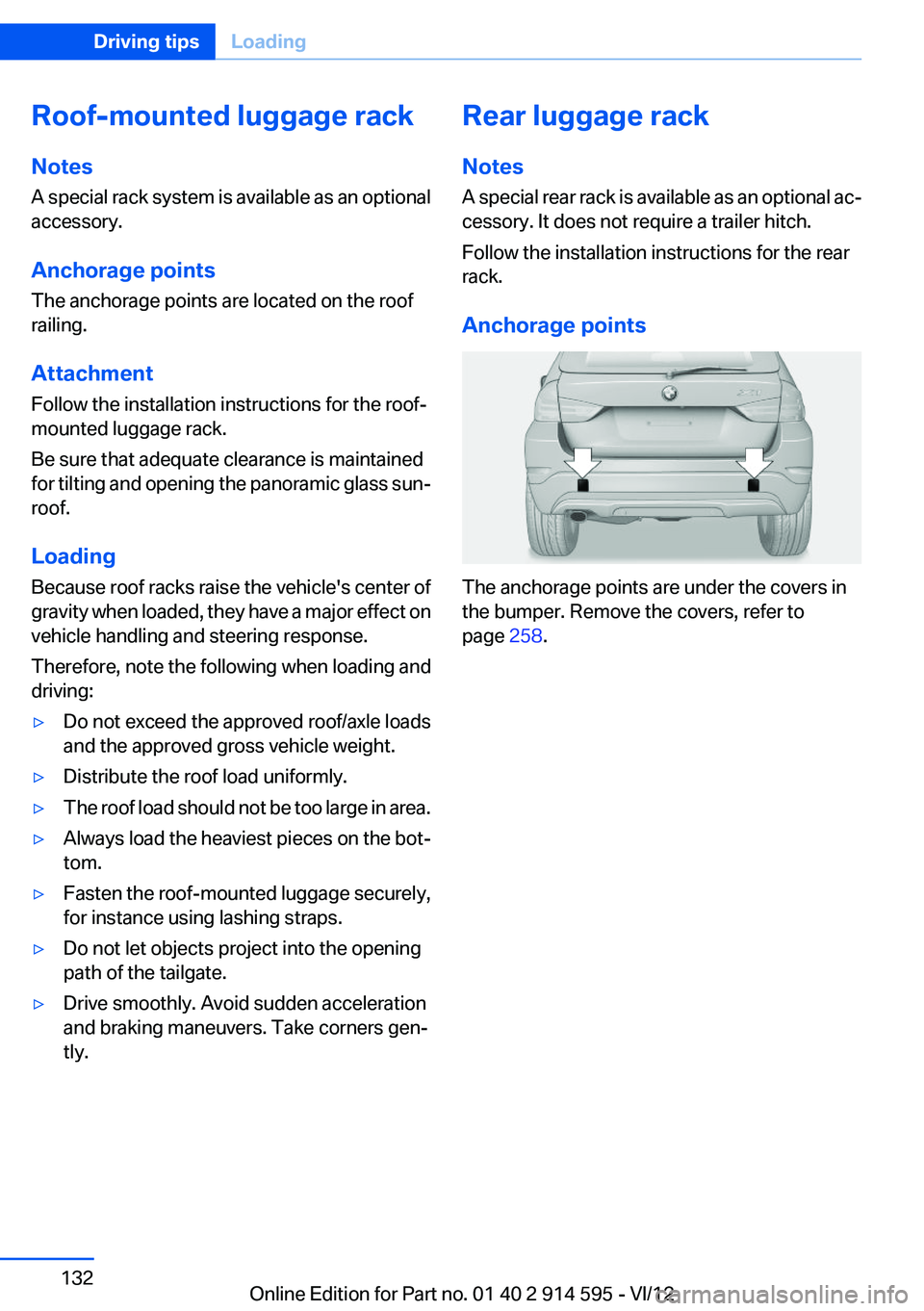
Anchorage points
The anchorage points are under the covers in
the bumper. Remove the covers, refer to
page 258.
Seite 132Driving tipsLoading132
Online Edition for Part no. 01 40 2 914 595 - VI/12
Page 133 of 291
Saving fuelVehicle equipment
This chapter describes all series equipment as
well as country-specific and special equipment
offered for this model series.Therefore, it also
describes equipment that may not be found in
your vehicle, for instance due to the selected
special equipment or the country version. This
also applies to safety-related functions and sys‐
tems.
General information
Your vehicle contains advanced technology for
the reduction of fuel consumption and emis‐
sions.
Fuel consumption depends on a number of dif‐
ferent factors.
The implementation of certain measures, driv‐
ing style and regular maintenance, refer to
page 243, can have an influence on fuel con‐
sumption and on the environmental impact.
Remove unnecessary cargo
Additional weight increases fuel consumption.
Remove attached parts
following use
Remove unneeded auxiliary mirrors, roof or rear
luggage racks after use.
Attached parts on the vehicle impair the aero‐
dynamics and increase the fuel consumption.Closing the windows and
panoramic glass sunroof
Driving with the panoramic glass sunroof and
windows open results in increased air resistance
and raises fuel consumption.
Check the tire inflation
pressure regularly
Check and, if necessary, correct the tire inflation
pressure, refer to page 228, at least twice a
month and before starting on a long trip.
Low tire inflation pressure increases rolling re‐
sistance and thus raises fuel consumption and
tire wear.
Drive away without delay
Do not wait for the engine to warm up while the
vehicle remains stationary. Start driving right
away, but at moderate engine speeds.
This is the fastest way for the cold engine to
reach its operating temperature.
Look well ahead when driving
Avoid unnecessary acceleration and braking.
By maintaining a suitable distance to the vehicle
driving ahead of you.
Driving smoothly and looking ahead reduces
fuel consumption.
Avoid high engine speeds
Driving at a low engine speed reduces fuel con‐
sumption and minimizes wear.Seite 133Saving fuelDriving tips133
Online Edition for Part no. 01 40 2 914 595 - VI/12
Page 202 of 291
2.Say the name after being prompted to do so.3.Confirm the prompt: ›Yes‹
Deleting all entries
1.›Delete phone book‹2.Confirm the prompt: ›Yes‹3.Confirm the prompt again: ›Yes‹
Reading and selecting entries
1.›Read phonebook‹2.When the desired entry is read aloud:
say ›Dial number‹
Selecting an entry
1.›Dial name‹2.Say the name after being prompted to do so.3.Confirm the prompt: ›Yes‹
Adjusting the volume
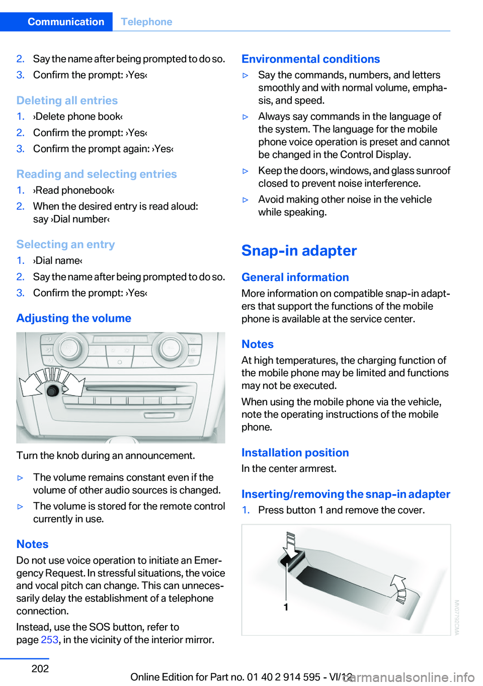
Turn the knob during an announcement.
▷The volume remains constant even if the
volume of other audio sources is changed.▷The volume is stored for the remote control
currently in use.
Notes
Do not use voice operation to initiate an Emer‐
gency Request. In stressful situations, the voice
and vocal pitch can change. This can unneces‐
sarily delay the establishment of a telephone
connection.
Instead, use the SOS button, refer to
page 253, in the vicinity of the interior mirror.
Environmental conditions▷Say the commands, numbers, and letters
smoothly and with normal volume, empha‐
sis, and speed.▷Always say commands in the language of
the system. The language for the mobile
phone voice operation is preset and cannot
be changed in the Control Display.▷Keep the doors, windows, and glass sunroof
closed to prevent noise interference.▷Avoid making other noise in the vehicle
while speaking.
Snap-in adapter
General information
More information on compatible snap-in adapt‐
ers that support the functions of the mobile
phone is available at the service center.
Notes
At high temperatures, the charging function of
the mobile phone may be limited and functions
may not be executed.
When using the mobile phone via the vehicle,
note the operating instructions of the mobile
phone.
Installation position
In the center armrest.
Inserting/removing the snap-in adapter
1.Press button 1 and remove the cover.Seite 202CommunicationTelephone202
Online Edition for Part no. 01 40 2 914 595 - VI/12
Page 244 of 291
Maintenance and repair should be performed by
your service center. Make sure to have regular
maintenance procedures recorded in the vehi‐
cle's Service and Warranty Information Booklet
for US models, and in the Warranty and Service
Guide Booklet for Canadian models. These en‐
tries are proof of regular maintenance.
Socket for OBD Onboard
Diagnosis
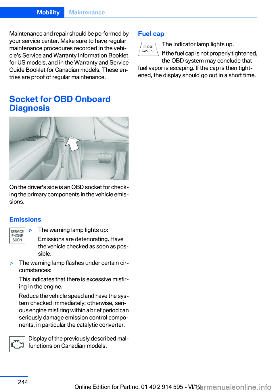
On the driver's side is an OBD socket for check‐
ing the primary components in the vehicle emis‐
sions.
Emissions
▷The warning lamp lights up:
Emissions are deteriorating. Have
the vehicle checked as soon as pos‐
sible.▷The warning lamp flashes under certain cir‐
cumstances:
This indicates that there is excessive misfir‐
ing in the engine.
Reduce the vehicle speed and have the sys‐
tem checked immediately; otherwise, seri‐
ous engine misfiring within a brief period can
seriously damage emission control compo‐
nents, in particular the catalytic converter.
Display of the previously described mal‐
functions on Canadian models.
Fuel cap
The indicator lamp lights up.
If the fuel cap is not properly tightened,
the OBD system may conclude that
fuel vapor is escaping. If the cap is then tight‐
ened, the display should go out in a short time.Seite 244MobilityMaintenance244
Online Edition for Part no. 01 40 2 914 595 - VI/12
Page 251 of 291
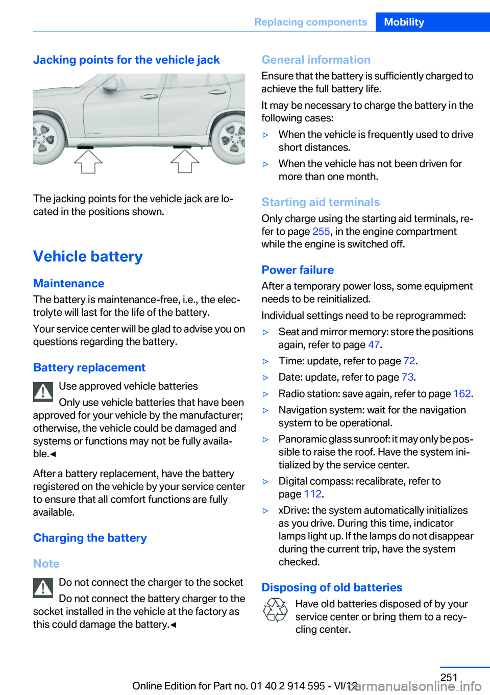
Jacking points for the vehicle jack
The jacking points for the vehicle jack are lo‐
cated in the positions shown.
Vehicle battery
Maintenance
The battery is maintenance-free, i.e., the elec‐
trolyte will last for the life of the battery.
Your service center will be glad to advise you on
questions regarding the battery.
Battery replacement Use approved vehicle batteries
Only use vehicle batteries that have been
approved for your vehicle by the manufacturer;
otherwise, the vehicle could be damaged and
systems or functions may not be fully availa‐
ble.◀
After a battery replacement, have the battery
registered on the vehicle by your service center
to ensure that all comfort functions are fully
available.
Charging the battery
Note Do not connect the charger to the socket
Do not connect the battery charger to the
socket installed in the vehicle at the factory as
this could damage the battery.◀
General information
Ensure that the battery is sufficiently charged to
achieve the full battery life.
It may be necessary to charge the battery in the
following cases:▷When the vehicle is frequently used to drive
short distances.▷When the vehicle has not been driven for
more than one month.
Starting aid terminals
Only charge using the starting aid terminals, re‐
fer to page 255, in the engine compartment
while the engine is switched off.
Power failure
After a temporary power loss, some equipment
needs to be reinitialized.
Individual settings need to be reprogrammed:
▷Seat and mirror memory: store the positions
again, refer to page 47.▷Time: update, refer to page 72.▷Date: update, refer to page 73.▷Radio station: save again, refer to page 162.▷Navigation system: wait for the navigation
system to be operational.▷Panoramic glass sunroof: it may only be pos‐
sible to raise the roof. Have the system ini‐
tialized by the service center.▷Digital compass: recalibrate, refer to
page 112.▷xDrive: the system automatically initializes
as you drive. During this time, indicator
lamps light up. If the lamps do not disappear
during the current trip, have the system
checked.
Disposing of old batteries
Have old batteries disposed of by your
service center or bring them to a recy‐
cling center.
Seite 251Replacing componentsMobility251
Online Edition for Part no. 01 40 2 914 595 - VI/12
Page 267 of 291

6Tailgate opening height: 80.0 inches/
2,031 mmSmallest turning circle dia.: 37 ft/11.3 m, with
xDrive: 38.7 ft/11.8 m.Height with roof antenna: 62 in/1,573 mm
Weights
X1 sDrive28iX1 xDrive28iX1 xDrive35iApproved gross vehicle
weightlbs/kg4,497/2,0404,707/2,1354,861/2,205Loadlbs/kg904/410904/410904/410Approved front axle loadlbs/kg2,116/9602,326/1,0552,425/1,100Approved rear axle loadlbs/kg2,546/1,1552,590/1,1752,646/1,200Approved roof load capacitylbs/kg165/75165/75165/75Cargo area capacitycu ft/liter25.0-56.0/420‐
1,35025.0-56.0/420‐
1,35025.0-56.0/420-
1,350
Capacities
NotesFuel tankFuel specifications, refer to
page 226X1 sDrive28iUS gal/litersapprox. 16.1/61X1 xDrive28i, X1 xDrive35iUS gal/litersapprox. 16.6/63Window washer system
With headlamp washer sys‐
temUS qt/litersapprox. 6.3/6Details, refer to page 61Seite 267Technical dataReference267
Online Edition for Part no. 01 40 2 914 595 - VI/12