2013 BMW M5 SEDAN steering
[x] Cancel search: steeringPage 78 of 230
NoteWhen the external temperature is very low, the
display may not work. Current driving direction
is recognizable at the engaged selector lever
position.
Gear change
Shifting in Sequential mode possible.
A shift in Drive mode causes a switch to Se‐
quential mode.
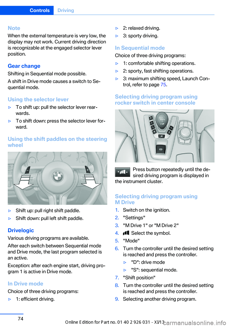
Using the selector lever▷To shift up: pull the selector lever rear‐
wards.▷To shift down: press the selector lever for‐
ward.
Using the shift paddles on the steering wheel
▷Shift up: pull right shift paddle.▷Shift down: pull left shift paddle.
Drivelogic
Various driving programs are available.
After each switch between Sequential mode
and Drive mode, the last program selected is
an active.
Exception: after each engine start, driving pro‐
gram 1 is active in Drive mode.
In Drive mode
Choice of three driving programs:
▷1: efficient driving.▷2: relaxed driving.▷3: sporty driving.
In Sequential mode Choice of three driving programs:
▷1: comfortable shifting operations.▷2: sporty, fast shifting operations.▷3: maximum shifting speed, Launch Con‐
trol, refer to page 75.
Selecting driving program using
rocker switch in center console
Press button repeatedly until the de‐
sired driving program is displayed in
the instrument cluster.
Selecting driving program using
M Drive
1.Switch on the ignition.2."Settings"3."M Drive 1" or "M Drive 2"4. Select the symbol.5."Mode"6.Turn the controller until the desired setting
is reached and press the controller.▷"D": drive mode▷"S": sequential mode.7."Shift position"8.Turn the controller until the desired setting
is reached and press the controller.9.Selecting another driving program.Seite 74ControlsDriving74
Online Edition for Part no. 01 40 2 909 953 - VI/13
Page 84 of 230

Overview: indicator/warning lampsSymbolFunction or systemTurn signal.Parking brake.Parking brake in Canadian models.High beams.High-beam Assistant.Parking lamps, headlamp control.Vehicle detection, Active Cruise
Control: collision warning.Cruise control.Lane departure warning.DSC Dynamic Stability Control.DSC Dynamic Stability Control.Tire Pressure Monitor.
Flat Tire Monitor.Safety belts.Airbag system.SymbolFunction or systemSteering system.Engine functions.Engine functions in Canadian mod‐
els.Brake system.Brake system in Canadian models.ABS Antilock Brake System.ABS Antilock Brake System in
Canadian models.At least one Check Control mes‐
sage is displayed or is stored.M Drive 1.M Drive 2.M Dynamic Mode.
Text messages
Text messages in combination with a symbol
in the instrument cluster explain a Check Con‐ trol message and the meaning of the indicator
and warning lamps.
Supplementary text messages
Additional information, such as on the cause of
a fault or the required action, can be called up
via Check Control.
Seite 80ControlsDisplays80
Online Edition for Part no. 01 40 2 909 953 - VI/13
Page 92 of 230
Selection lists in the
instrument cluster
The concept
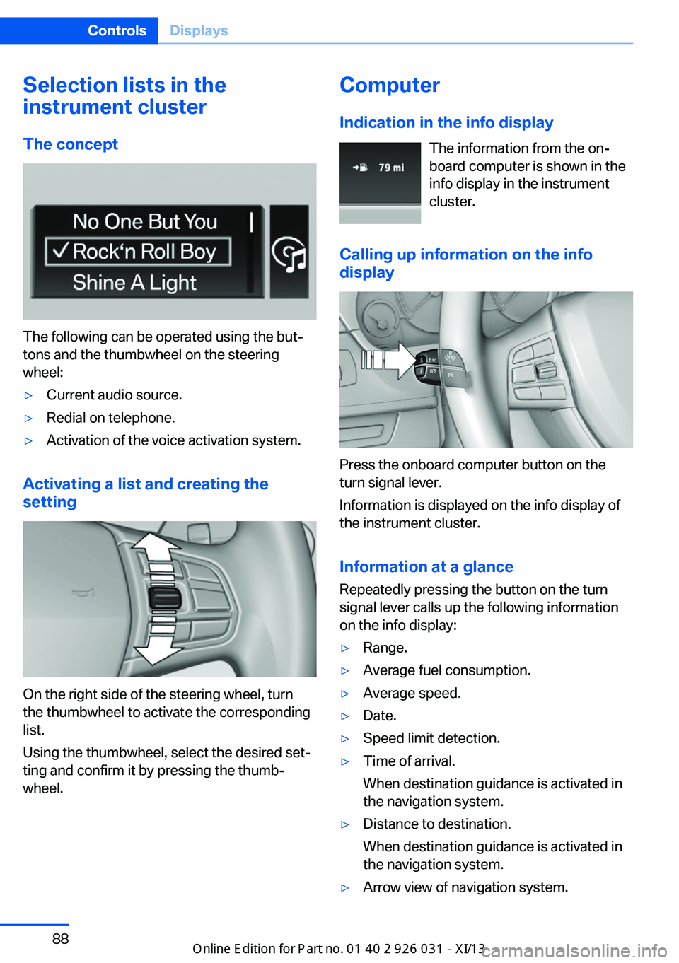
The following can be operated using the but‐
tons and the thumbwheel on the steering
wheel:
▷Current audio source.▷Redial on telephone.▷Activation of the voice activation system.
Activating a list and creating the
setting
On the right side of the steering wheel, turn
the thumbwheel to activate the corresponding
list.
Using the thumbwheel, select the desired set‐
ting and confirm it by pressing the thumb‐
wheel.
Computer
Indication in the info display The information from the on‐
board computer is shown in the
info display in the instrument
cluster.
Calling up information on the info
display
Press the onboard computer button on the
turn signal lever.
Information is displayed on the info display of
the instrument cluster.
Information at a glance
Repeatedly pressing the button on the turn
signal lever calls up the following information
on the info display:
▷Range.▷Average fuel consumption.▷Average speed.▷Date.▷Speed limit detection.▷Time of arrival.
When destination guidance is activated in
the navigation system.▷Distance to destination.
When destination guidance is activated in
the navigation system.▷Arrow view of navigation system.Seite 88ControlsDisplays88
Online Edition for Part no. 01 40 2 909 953 - VI/13
Page 97 of 230
The setting is stored for the remote control
currently in use.
Automatic headlamp control
Switch position
: the low beams are
switched on and off automatically, e.g., in tun‐
nels, in twilight or if there is precipitation. The
indicator lamp in the instrument cluster lights
up.
A blue sky with the sun low on the horizon can
cause the lights to be switched on.
The low beams always stay on when the fog
lamps are switched on.
Personal responsibility
The automatic headlamp control cannot
serve as a substitute for your personal judg‐
ment in determining when the lamps should be
switched on in response to ambient lighting
conditions.
For example, the sensors are unable to detect
fog or hazy weather. To avoid safety risks, you
should always switch on the lamps manually
under these conditions.◀
Daytime running lights With the ignition switched on, the daytime run‐
ning lights light up in position 0,
or .
After the ignition is switched off, the parking
lamps light up in position
.
Activating/deactivating
In some countries, daytime running lights are
compulsory, so it may not be possible to deac‐
tivate the daytime running lights.
1."Settings"2."Lighting"3."Daytime running lamps"
The setting is stored for the remote control
currently in use.
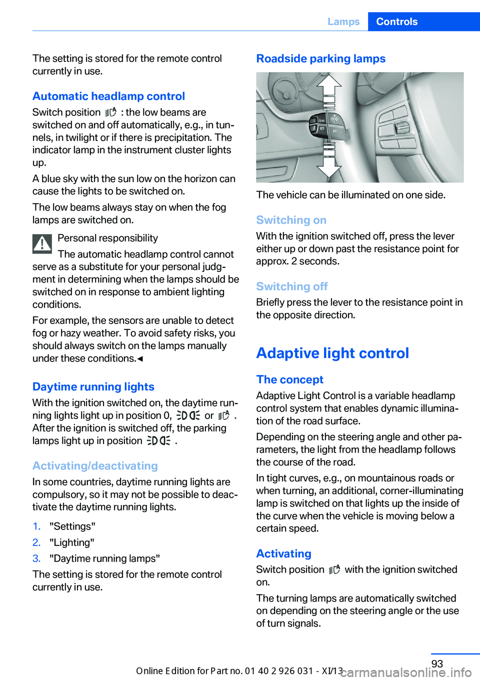
Roadside parking lamps
The vehicle can be illuminated on one side.
Switching on With the ignition switched off, press the lever
either up or down past the resistance point for
approx. 2 seconds.
Switching off Briefly press the lever to the resistance point in
the opposite direction.
Adaptive light control The concept Adaptive Light Control is a variable headlamp
control system that enables dynamic illumina‐
tion of the road surface.
Depending on the steering angle and other pa‐ rameters, the light from the headlamp follows
the course of the road.
In tight curves, e.g., on mountainous roads or
when turning, an additional, corner-illuminating
lamp is switched on that lights up the inside of
the curve when the vehicle is moving below a certain speed.
Activating Switch position
with the ignition switched
on.
The turning lamps are automatically switched
on depending on the steering angle or the use
of turn signals.
Seite 93LampsControls93
Online Edition for Part no. 01 40 2 909 953 - VI/13
Page 102 of 230
Protective action
Airbags are not triggered in every impact situa‐
tion, e.g., in less severe accidents or rear-end
collisions.
Information on how to ensure the optimal
protective effect of the airbags▷Keep at a distance from the airbags.▷Always grasp the steering wheel on the
steering wheel rim, holding your hands at
the 3 o'clock and 9 o'clock positions, to
keep the danger of injury to your hands or
arms as low as possible if the airbag is trig‐
gered.▷There should be no people, animals, or ob‐
jects between an airbag and a person.▷Do not use the cover of the front airbag on
the front passenger side as a storage area.▷Keep the dashboard and window on the
front passenger side clear, i.e., do not
cover with adhesive labels or coverings,
and do not attach holders such as for navi‐
gation instruments and mobile phones.▷Make sure that the front passenger is sit‐
ting correctly, i.e., keeps his or her feet and
legs in the footwell; otherwise, leg injuries
can occur if the front airbag is triggered.▷Do not place slip covers, seat cushions or
other objects on the front passenger seat
that are not approved specifically for seats
with integrated side airbags.▷Do not hang pieces of clothing, such as
jackets, over the backrests.▷Make sure that occupants keep their heads
away from the side airbag and do not rest
against the head airbag; otherwise, injuries
can occur if the airbags are triggered.▷Do not remove the airbag restraint system.▷Do not remove the steering wheel.▷Do not apply adhesive materials to the air‐
bag cover panels, cover them or modify
them in any way.▷Never modify either the individual compo‐
nents or the wiring in the airbag system.
This also applies to steering wheel covers,
the dashboard, the seats, the roof pillars
and the sides of the headliner.◀
Even when all instructions are followed closely,
injury from contact with the airbags cannot be
ruled out in certain situations.
The ignition and inflation noise may lead to
short-term and, in most cases, temporary
hearing impairment in sensitive individuals.
In the case of a malfunction, deactivation
and after triggering of the airbags
Do not touch the individual components imme‐
diately after the system has been triggered;
otherwise, there is the danger of burns.
Only have the airbags checked, repaired or dis‐
mantled and the airbag generator scrapped by
your service center or a workshop that has the
necessary authorization for handling explo‐
sives.
Non-professional attempts to service the sys‐
tem could lead to failure in an emergency or
undesired triggering of the airbag, either of
which could result in injury.◀
Warnings and information on the airbags are
also found on the sun visors.
Functional readiness of the airbag
system
When the ignition is switch on, the
warning lamp in the instrument cluster
lights up briefly and thereby indicates
the operational readiness of the entire airbag
system and the belt tensioner.
Airbag system malfunctioning
▷Warning lamp does not come on when the
ignition is turned on.▷The warning lamp lights up continuously.Seite 98ControlsSafety98
Online Edition for Part no. 01 40 2 909 953 - VI/13
Page 105 of 230
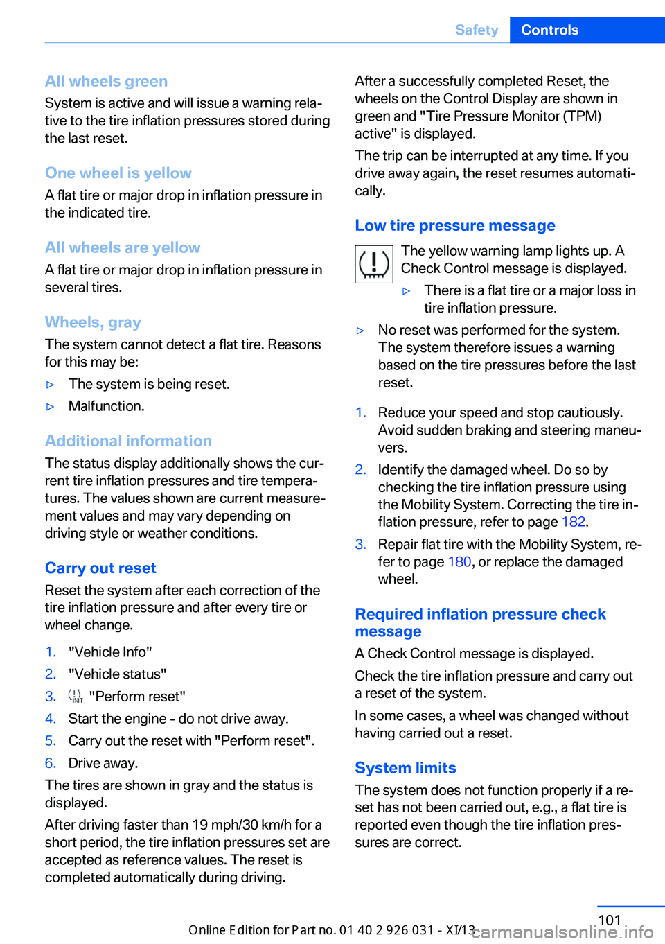
All wheels green
System is active and will issue a warning rela‐
tive to the tire inflation pressures stored during
the last reset.
One wheel is yellow
A flat tire or major drop in inflation pressure in
the indicated tire.
All wheels are yellow A flat tire or major drop in inflation pressure in
several tires.
Wheels, gray
The system cannot detect a flat tire. Reasons
for this may be:▷The system is being reset.▷Malfunction.
Additional information
The status display additionally shows the cur‐
rent tire inflation pressures and tire tempera‐
tures. The values shown are current measure‐
ment values and may vary depending on
driving style or weather conditions.
Carry out reset Reset the system after each correction of the
tire inflation pressure and after every tire or
wheel change.
1."Vehicle Info"2."Vehicle status"3. "Perform reset"4.Start the engine - do not drive away.5.Carry out the reset with "Perform reset".6.Drive away.
The tires are shown in gray and the status is
displayed.
After driving faster than 19 mph/30 km/h for a
short period, the tire inflation pressures set are
accepted as reference values. The reset is
completed automatically during driving.
After a successfully completed Reset, the
wheels on the Control Display are shown in
green and "Tire Pressure Monitor (TPM)
active" is displayed.
The trip can be interrupted at any time. If you
drive away again, the reset resumes automati‐
cally.
Low tire pressure message The yellow warning lamp lights up. A
Check Control message is displayed.▷There is a flat tire or a major loss in
tire inflation pressure.▷No reset was performed for the system.
The system therefore issues a warning
based on the tire pressures before the last
reset.1.Reduce your speed and stop cautiously.
Avoid sudden braking and steering maneu‐
vers.2.Identify the damaged wheel. Do so by
checking the tire inflation pressure using
the Mobility System. Correcting the tire in‐
flation pressure, refer to page 182.3.Repair flat tire with the Mobility System, re‐
fer to page 180, or replace the damaged
wheel.
Required inflation pressure check
message
A Check Control message is displayed.
Check the tire inflation pressure and carry out
a reset of the system.
In some cases, a wheel was changed without
having carried out a reset.
System limits
The system does not function properly if a re‐
set has not been carried out, e.g., a flat tire is
reported even though the tire inflation pres‐
sures are correct.
Seite 101SafetyControls101
Online Edition for Part no. 01 40 2 909 953 - VI/13
Page 107 of 230
In the event of a pressure loss, the diameter
and therefore the rotational speed of the corre‐
sponding wheel change. This is detected and
reported as a flat tire.
Functional requirements
The system must have been initialized when
the tire inflation pressure was correct; other‐
wise, reliable signaling of a flat tire is not en‐
sured. Initialize the system after each correc‐ tion of the tire inflation pressure and afterevery tire or wheel change.
Status display The current status of the Flat Tire Monitor can
be displayed on the Control Display, e.g.,
whether or not the FTM is active.1."Vehicle Info"2."Vehicle status"3. "Flat Tire Monitor (FTM)"
The status is displayed.
Initialization
The initialization process adopts the set infla‐
tion tire pressures as reference values for the
detection of a flat tire. Initialization is started by
confirming the inflation pressures.
Do not initialize the system when driving with
snow chains.
1."Vehicle Info"2."Vehicle status"3. "Perform reset"4.Start the engine - do not drive away.5.Start the initialization with "Perform reset".6.Drive away.
The initialization is completed while driving,
which can be interrupted at any time.
The initialization automatically continues when
driving resumes.
Indication of a flat tire
The yellow warning lamp lights up. A
Check Control message is displayed.
There is a flat tire or a major loss in tire
inflation pressure.1.Reduce your speed and stop cautiously.
Avoid sudden braking and steering maneu‐
vers.2.Identify the damaged wheel. Do so by
checking the tire inflation pressure using
the Mobility System. If the tire inflation
pressure in all tires is correct, the Flat Tire
Monitor may not have been initialized. In
this case, initialize the system.3.Repair flat tire with the Mobility System, re‐
fer to page 180, or replace the damaged
wheel.
System limits
Sudden tire damage
Sudden serious tire damage caused by
external influences cannot be indicated in ad‐
vance.◀
A natural, even pressure loss in all four tires
cannot be detected. Therefore, check the tire
inflation pressure regularly.
The system could be delayed or malfunction in
the following situations:
▷When the system has not been initialized.▷When driving on a snowy or slippery road
surface.▷Sporty driving style: slip in the drive
wheels, high lateral acceleration.▷When driving with snow chains.
Intelligent Safety
The concept
Depending on how the vehicle is equipped, In‐
telligent Safety consists of one or more of the
Seite 103SafetyControls103
Online Edition for Part no. 01 40 2 909 953 - VI/13
Page 109 of 230
located within the detection range of the sys‐
tem.
At a glance
Button in the vehicle
Intelligent Safety button
Switching on/off
Switching on automatically The system is automatically active every time
the engine is started using the Start/Stop but‐
ton.
Switching off The system is only switched off until the next
time the engine is started with the Start/Stop
button.
Press the button.
The LED goes out.
Warning with braking function Adapting your speed and driving style
The warning does not relieve the driver
of the responsibility to adapt his or her driving
speed and style to the traffic conditions.◀
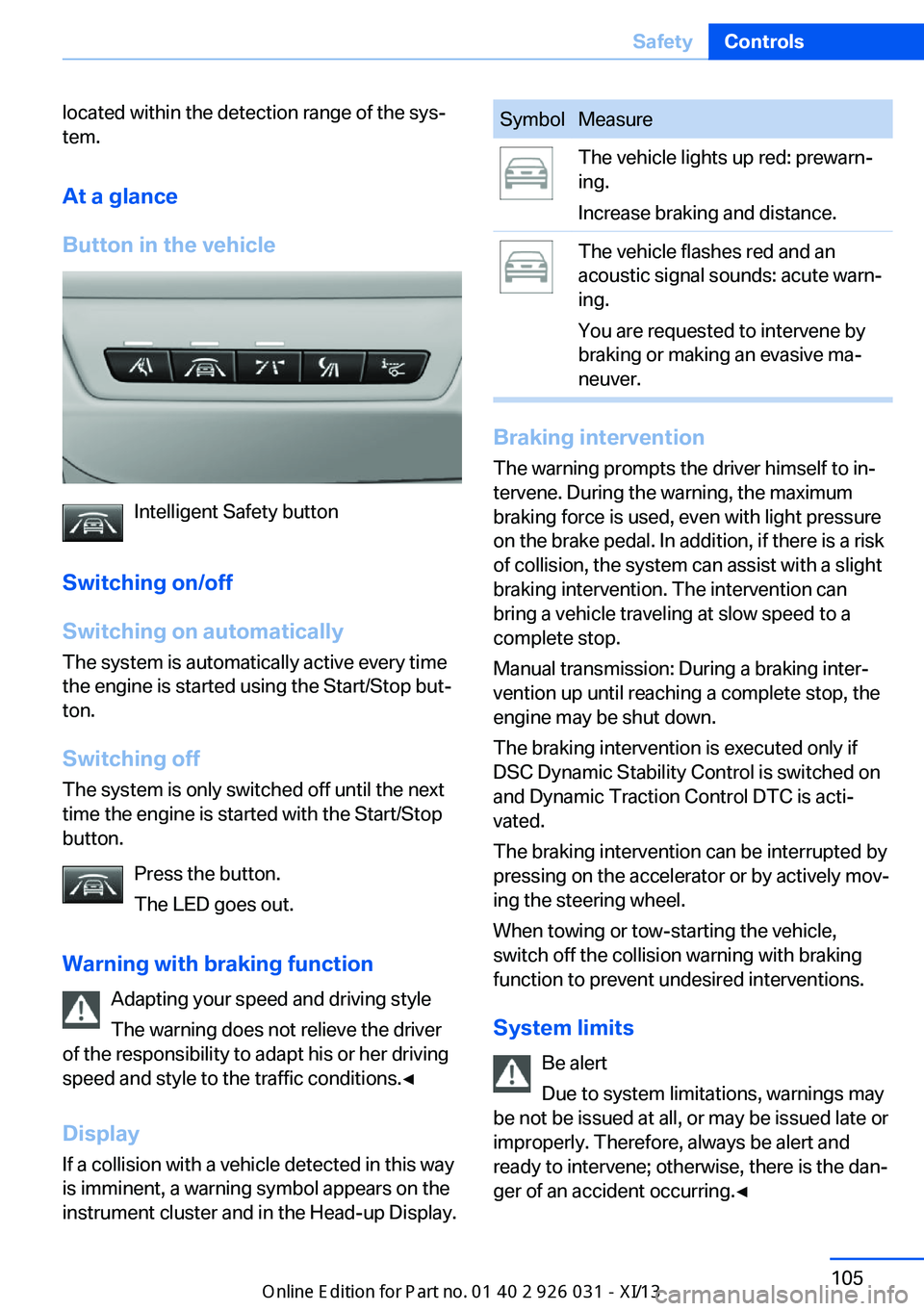
Display
If a collision with a vehicle detected in this way
is imminent, a warning symbol appears on the
instrument cluster and in the Head-up Display.
SymbolMeasureThe vehicle lights up red: prewarn‐
ing.
Increase braking and distance.The vehicle flashes red and an
acoustic signal sounds: acute warn‐
ing.
You are requested to intervene by
braking or making an evasive ma‐
neuver.
Braking intervention
The warning prompts the driver himself to in‐
tervene. During the warning, the maximum
braking force is used, even with light pressure
on the brake pedal. In addition, if there is a risk
of collision, the system can assist with a slight
braking intervention. The intervention can
bring a vehicle traveling at slow speed to a
complete stop.
Manual transmission: During a braking inter‐
vention up until reaching a complete stop, the
engine may be shut down.
The braking intervention is executed only if
DSC Dynamic Stability Control is switched on
and Dynamic Traction Control DTC is acti‐
vated.
The braking intervention can be interrupted by
pressing on the accelerator or by actively mov‐
ing the steering wheel.
When towing or tow-starting the vehicle,
switch off the collision warning with braking
function to prevent undesired interventions.
System limits Be alert
Due to system limitations, warnings may
be not be issued at all, or may be issued late or
improperly. Therefore, always be alert and ready to intervene; otherwise, there is the dan‐
ger of an accident occurring.◀
Seite 105SafetyControls105
Online Edition for Part no. 01 40 2 909 953 - VI/13