2013 BMW M5 SEDAN towing
[x] Cancel search: towingPage 46 of 230
▷When a seat position switch is pressed.▷When a button of the seat, mirror, and
steering wheel memory is pressed briefly.
Activating the setting
1."Settings"2."Doors/key"3."Last seat position autom."
Alarm system
The conceptThe vehicle alarm system responds to:
▷Opening of a door, the hood or the trunk
lid.▷Movements in the vehicle.▷Changes in the vehicle tilt, e.g., during at‐
tempts to steal a wheel or when towing the
car.▷Interruptions in battery voltage.
The alarm system briefly indicates tampering:
▷By sounding an acoustic alarm.▷By switching on the hazard warning sys‐
tem.▷By flashing the high beams.
Arming and disarming the alarm
system
General information
When you lock or unlock the vehicle, either
with the remote control, Comfort Access or at
the door lock the alarm system is armed or dis‐
armed at the same time.
Door lock and armed alarm systemUnlocking via the door lock will trigger the
alarm on some country-specific versions.
In order to terminate this alarm, unlock vehicle
with the remote control or switch on the igni‐
tion, if necessary, by emergency detection of
the remote control.
Trunk lid and armed alarm system The trunk lid can be opened even when the
alarm system is armed.
Press the button on the remote con‐
trol for approx. 1 second.
With Comfort Access the trunk lid opens with
no-touch activation, refer to page 40.
After the trunk lid is closed, it is locked and
monitored again if the doors are locked. The
hazard warning system flashes once.
In some vehicle equipment variants, the trunk
lid can only be opened using the remote con‐
trol if the vehicle was unlocked first.
Panic mode You can trigger the alarm system if you find
yourself in a dangerous situation.
Press the button on the remote con‐
trol for at least 3 seconds.
To switch off the alarm: press any button.
Switching off the alarm▷Unlock the vehicle using the remote con‐
trol.▷With Comfort Access: If you are carrying
the remote control with you, pull on the
driver side or front passenger side door
handle.Seite 42ControlsOpening and closing42
Online Edition for Part no. 01 40 2 909 953 - VI/13
Page 109 of 230
located within the detection range of the sys‐
tem.
At a glance
Button in the vehicle
Intelligent Safety button
Switching on/off
Switching on automatically The system is automatically active every time
the engine is started using the Start/Stop but‐
ton.
Switching off The system is only switched off until the next
time the engine is started with the Start/Stop
button.
Press the button.
The LED goes out.
Warning with braking function Adapting your speed and driving style
The warning does not relieve the driver
of the responsibility to adapt his or her driving
speed and style to the traffic conditions.◀
Display
If a collision with a vehicle detected in this way
is imminent, a warning symbol appears on the
instrument cluster and in the Head-up Display.
SymbolMeasureThe vehicle lights up red: prewarn‐
ing.
Increase braking and distance.The vehicle flashes red and an
acoustic signal sounds: acute warn‐
ing.
You are requested to intervene by
braking or making an evasive ma‐
neuver.
Braking intervention
The warning prompts the driver himself to in‐
tervene. During the warning, the maximum
braking force is used, even with light pressure
on the brake pedal. In addition, if there is a risk
of collision, the system can assist with a slight
braking intervention. The intervention can
bring a vehicle traveling at slow speed to a
complete stop.
Manual transmission: During a braking inter‐
vention up until reaching a complete stop, the
engine may be shut down.
The braking intervention is executed only if
DSC Dynamic Stability Control is switched on
and Dynamic Traction Control DTC is acti‐
vated.
The braking intervention can be interrupted by
pressing on the accelerator or by actively mov‐
ing the steering wheel.
When towing or tow-starting the vehicle,
switch off the collision warning with braking
function to prevent undesired interventions.
System limits Be alert
Due to system limitations, warnings may
be not be issued at all, or may be issued late or
improperly. Therefore, always be alert and ready to intervene; otherwise, there is the dan‐
ger of an accident occurring.◀
Seite 105SafetyControls105
Online Edition for Part no. 01 40 2 909 953 - VI/13
Page 112 of 230
and Dynamic Traction Control DTC is acti‐
vated.
The braking intervention can be interrupted by
pressing on the accelerator or by actively mov‐
ing the steering wheel.
When towing or tow-starting the vehicle,
switch off the pedestrian warning to prevent
undesired interventions.
System limits Be alert
Due to system limitations, warnings may
be not be issued at all, or may be issued late or
improperly. Therefore, always be alert and
ready to intervene; otherwise, there is the dan‐
ger of an accident occurring.◀
Detection range
The detection capability of the camera is lim‐ ited.
This may result in the warning not being is‐
sued or being issued late.
For example, the following situations may not
be detected:▷Partially covered pedestrians.▷Pedestrians that are not detected as such
because of the viewing angle or contour.▷Pedestrians outside of the detection range.▷Pedestrians below a body size of approx.
32 in/80 cm.
Functional limitations
The system may not be fully functional or may
not be available in the following situations:
▷In heavy fog, rain, sprayed water or snow‐
fall.▷In tight curves.▷If the camera view field or the front wind‐
shield are dirty or covered.▷When driving toward bright lights.▷Up to 10 seconds after the start of the en‐
gine, via the Start/Stop knob.▷During calibration of the camera immedi‐
ately after vehicle shipment.
Night Vision with Pedestrian
and Animal Detection
The concept Night Vision with pedestrian and animal detec‐
tion is a night vision system.
An infrared camera records the area in front of
the vehicle and issues a warning if it detects
pedestrians and animals on the street. Warm
objects that are similar in shape to human be‐
ings or animals are detected by the system. If necessary, the heat image can be displayed on
the Control Display.
Heat image
The image shows the heat radiated by objects
in the field of view of the camera.
Warm objects have a light appearance and
cold objects, a dark appearance.
The ability to detect an object depends on the
temperature difference between the object
and the background and on the level of heat
radiation emitted by the object. Objects that
are similar in temperature to the environment
or that radiate very little heat are difficult to de‐
tect.
For safety reasons, when driving at speeds
above approx. 3 mph/5 km/h and in low ambi‐
Seite 108ControlsSafety108
Online Edition for Part no. 01 40 2 909 953 - VI/13
Page 169 of 230
Stowing cargo▷Cover sharp edges and corners on the
cargo.▷Heavy cargo: stow as far forward as possi‐
ble, directly behind and at the bottom of
the rear passenger seat backrests.▷Very heavy cargo: when the rear seat is not
occupied, secure each of the outer safety
belts in the opposite buckle.▷If necessary, fold down the rear backrests
to stow cargo.▷Do not stack cargo above the top edge of
the backrests.
Securing cargo
Lashing eyes in the cargo area
To secure the cargo there are four lashing
eyes in the cargo area.
Securing cargo
▷Smaller and lighter items: secure with re‐
taining straps or with a cargo net or draw
straps.▷Larger and heavy objects: secure with
cargo straps.
Cargo straps, cargo netting, retaining straps or
draw straps on the lashing eyes in the cargo
area.
Securing cargo
Always position and secure the cargo as
described above; otherwise, it can endanger
the car's occupants if sudden braking or
swerving becomes necessary.
Heavy or hard objects should not be carried
loose inside the car; otherwise, they could be
thrown around as a result of hard braking, sud‐
den swerves, etc., and endanger the occu‐
pants.◀
Roof-mounted luggage rack
Note Roof racks are available as special accessories.
Securing
Follow the installation instructions of the roof
rack.
Roof drip rail with flaps
The anchorage points are located in the roof
drip rail above the doors.
Fold the cover outward.
Loading Be sure that adequate clearance is maintained
for tilting and opening the glass sunroof.
Because roof racks raise the vehicle's center
of gravity when loaded, they have a major ef‐
fect on vehicle handling and steering re‐
sponse.
Seite 165LoadingDriving tips165
Online Edition for Part no. 01 40 2 909 953 - VI/13
Page 186 of 230
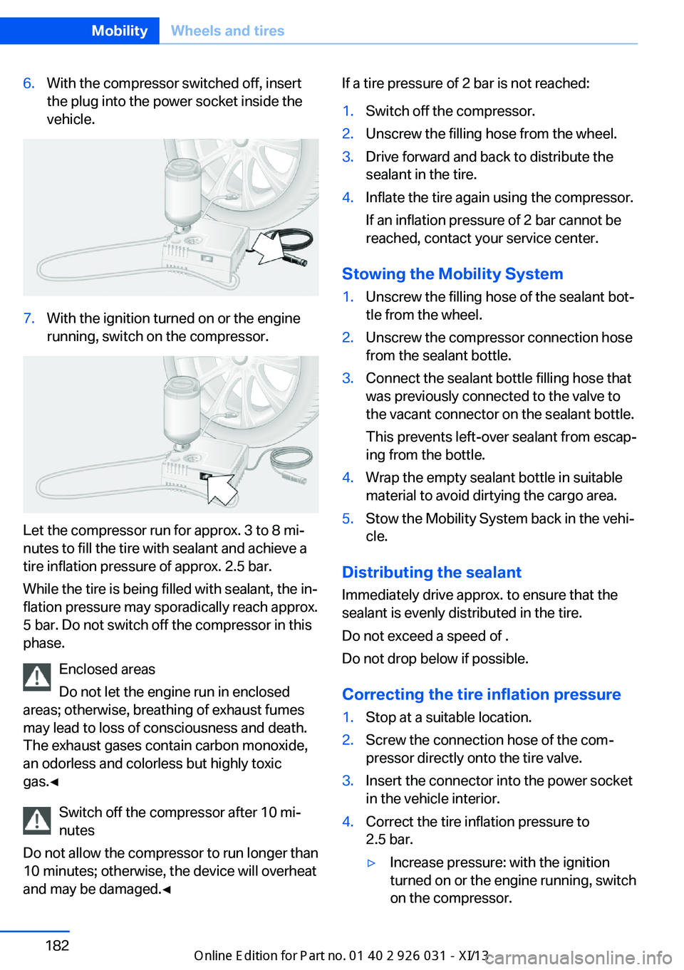
6.With the compressor switched off, insert
the plug into the power socket inside the
vehicle.7.With the ignition turned on or the engine
running, switch on the compressor.
Let the compressor run for approx. 3 to 8 mi‐
nutes to fill the tire with sealant and achieve a
tire inflation pressure of approx. 2.5 bar.
While the tire is being filled with sealant, the in‐
flation pressure may sporadically reach approx.
5 bar. Do not switch off the compressor in this
phase.
Enclosed areas
Do not let the engine run in enclosed
areas; otherwise, breathing of exhaust fumes
may lead to loss of consciousness and death.
The exhaust gases contain carbon monoxide,
an odorless and colorless but highly toxic
gas.◀
Switch off the compressor after 10 mi‐
nutes
Do not allow the compressor to run longer than
10 minutes; otherwise, the device will overheat
and may be damaged.◀
If a tire pressure of 2 bar is not reached:1.Switch off the compressor.2.Unscrew the filling hose from the wheel.3.Drive forward and back to distribute the
sealant in the tire.4.Inflate the tire again using the compressor.
If an inflation pressure of 2 bar cannot be
reached, contact your service center.
Stowing the Mobility System
1.Unscrew the filling hose of the sealant bot‐
tle from the wheel.2.Unscrew the compressor connection hose
from the sealant bottle.3.Connect the sealant bottle filling hose that
was previously connected to the valve to
the vacant connector on the sealant bottle.
This prevents left-over sealant from escap‐
ing from the bottle.4.Wrap the empty sealant bottle in suitable
material to avoid dirtying the cargo area.5.Stow the Mobility System back in the vehi‐
cle.
Distributing the sealant
Immediately drive approx. to ensure that the
sealant is evenly distributed in the tire.
Do not exceed a speed of .
Do not drop below if possible.
Correcting the tire inflation pressure
1.Stop at a suitable location.2.Screw the connection hose of the com‐
pressor directly onto the tire valve.3.Insert the connector into the power socket
in the vehicle interior.4.Correct the tire inflation pressure to
2.5 bar.▷Increase pressure: with the ignition
turned on or the engine running, switch
on the compressor.Seite 182MobilityWheels and tires182
Online Edition for Part no. 01 40 2 909 953 - VI/13
Page 206 of 230
other attempt in order to allow the dis‐
charged battery to recharge.3.Let both engines run for several minutes.4.Disconnect the jumper cables in the re‐
verse order.
Check the battery and recharge if necessary.
Tow-starting and towing Manual transmission
Observe before towing your vehicle
Gearshift lever in neutral position.
Towing When the parking brake is blocked
The parking brake cannot be released
manually.
Do not tow the vehicle with the parking brake
blocked, or the vehicle can be damaged.
Contact your service center.◀
Follow the towing instructions
Follow all towing instructions; otherwise,
vehicle damage or accidents may occur.◀
▷Make sure that the ignition is switched on;
otherwise, the low beams, tail lamps, turn
signals, and windshield wipers may be un‐
available.▷Do not tow the vehicle with the rear axle
tilted, as the front wheels could turn.▷When the engine is stopped, there is no
power assist. Consequently, more force
needs to be applied when braking and
steering.▷Larger steering wheel movements are re‐
quired.▷The towing vehicle must not be lighter
than the vehicle being towed; otherwise,
it will not be possible to control the vehicle
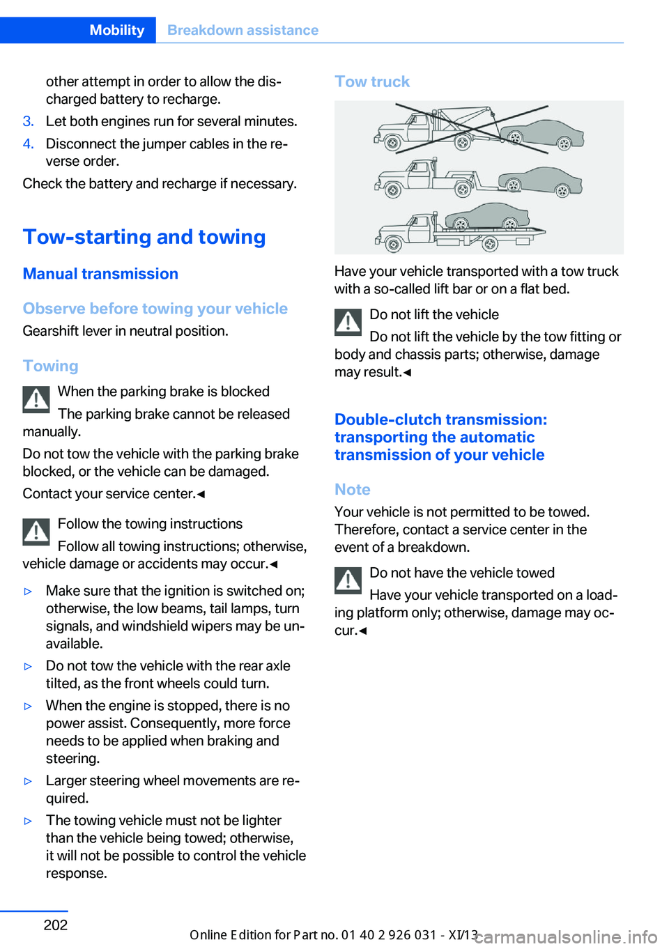
response.Tow truck
Have your vehicle transported with a tow truck
with a so-called lift bar or on a flat bed.
Do not lift the vehicle
Do not lift the vehicle by the tow fitting or
body and chassis parts; otherwise, damage
may result.◀
Double-clutch transmission:
transporting the automatic
transmission of your vehicle
Note Your vehicle is not permitted to be towed.
Therefore, contact a service center in the
event of a breakdown.
Do not have the vehicle towedHave your vehicle transported on a load‐
ing platform only; otherwise, damage may oc‐
cur.◀
Seite 202MobilityBreakdown assistance202
Online Edition for Part no. 01 40 2 909 953 - VI/13
Page 207 of 230
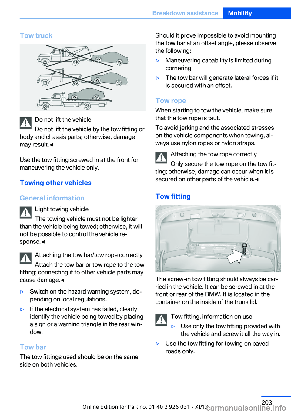
Tow truck
Do not lift the vehicle
Do not lift the vehicle by the tow fitting or
body and chassis parts; otherwise, damage
may result.◀
Use the tow fitting screwed in at the front for
maneuvering the vehicle only.
Towing other vehicles
General information Light towing vehicle
The towing vehicle must not be lighter
than the vehicle being towed; otherwise, it will
not be possible to control the vehicle re‐
sponse.◀
Attaching the tow bar/tow rope correctly
Attach the tow bar or tow rope to the tow
fitting; connecting it to other vehicle parts may
cause damage.◀
▷Switch on the hazard warning system, de‐
pending on local regulations.▷If the electrical system has failed, clearly
identify the vehicle being towed by placing
a sign or a warning triangle in the rear win‐
dow.
Tow bar
The tow fittings used should be on the same
side on both vehicles.
Should it prove impossible to avoid mounting
the tow bar at an offset angle, please observe
the following:▷Maneuvering capability is limited during
cornering.▷The tow bar will generate lateral forces if it
is secured with an offset.
Tow rope
When starting to tow the vehicle, make sure
that the tow rope is taut.
To avoid jerking and the associated stresses
on the vehicle components when towing, al‐
ways use nylon ropes or nylon straps.
Attaching the tow rope correctly
Only secure the tow rope on the tow fit‐
ting; otherwise, damage can occur when it is
secured on other parts of the vehicle.◀
Tow fitting
The screw-in tow fitting should always be car‐
ried in the vehicle. It can be screwed in at the
front or rear of the BMW. It is located in the
container on the inside of the trunk lid.
Tow fitting, information on use
▷Use only the tow fitting provided with
the vehicle and screw it all the way in.▷Use the tow fitting for towing on paved
roads only.Seite 203Breakdown assistanceMobility203
Online Edition for Part no. 01 40 2 909 953 - VI/13
Page 220 of 230
Everything from A to Z
IndexA ABS, Antilock Brake Sys‐ tem 117
Acceleration Assistant, refer to Launch Control 75
Activated-charcoal filter 137
Active Blind Spot Detec‐ tion 113
Active M differential 119
Active Protection 114
Active seat, front 49
Active seat ventilation, front 50
Adaptive brake lights, refer to Brake force display 114
Adaptive light control 93
Additives, oil 187
Adjustments, seats/head re‐ straints 48
After washing vehicle 206
Airbags 97
Airbags, indicator/warning light 98
Air circulation, refer to Recir‐ culated-air mode 136
Air distribution, manual 135
Air drying, refer to Cooling function 136
Air flow, automatic climate control 135
Air pressure, tires 175
Air vents, refer to Ventila‐ tion 137
Alarm system 42
Alarm, unintentional 43
All around the center con‐ sole 14
All around the headliner 15
All around the steering wheel 12 All-season tires, refer to Win‐
ter tires 180
Alternating-code hand-held transmitter 142
Alternative oil types 187
Ambient light 95
Antifreeze, washer fluid 71
Antilock Brake System, ABS 117
Anti-slip control, refer to DSC 117
Approved engine oils 187
Armrest, refer to Center arm‐ rest 151
Arrival time 89
Ashtray 143
Ashtray, front 143, 144
Ashtray, rear 144
Assistance, Roadside Assis‐ tance 200
Assistance when driving off 117
Attentiveness assistant 115
AUTO intensity 135
Automatic car wash 205
Automatic climate con‐ trol 134
Automatic Curb Monitor 55
Automatic deactivation, front passenger airbags 99
Automatic headlamp con‐ trol 93
Automatic locking 41
Automatic recirculated-air control 136
Automatic Soft Closing, doors 36
Automatic tailgate 37
AUTO program, automatic cli‐ mate control 135
AUTO program, intensity 135 Auto Start/Stop function 65
Average fuel consumption 89
Average speed 89
Axle loads, weights 213
B Backrest curvature, refer to Lumbar support 49
Backrest, width 49
Backup camera 125
Band-aids, refer to First aid kit 200
Bar for tow-starting/ towing 203
Battery replacement, vehicle battery 197
Battery replacement, vehicle remote control 30
Battery, vehicle 197
Belts, safety belts 51
Beverage holder, cu‐ pholder 152
Blinds, sun protection 45
BMW Assist, see user's manual for Navigation, En‐
tertainment and Communi‐
cation
BMW Homepage 6
BMW Internet page 6
BMW maintenance sys‐ tem 190
BMW M technology 158
Bottle holder, refer to Cu‐ pholder 152
Brake assistant 117
Brake discs, breaking in 160
Brake force display 114
Brake lamps, brake force dis‐ play 114 Seite 216ReferenceEverything from A to Z216
Online Edition for Part no. 01 40 2 909 953 - VI/13