2013 BMW ACTIVEHYBRID3 engine
[x] Cancel search: enginePage 180 of 220

CoolantVehicle equipment
All standard, country-specific and optional
equipment that is offered in the model series is
described in this chapter. Therefore, equipment
is also described that is not available in a vehicle,
e. g., because of the selected optional equip‐
ment or country variant. This also applies for
safety-related functions and systems.
General information Danger of burns from hot engine
Do not open the cooling system while the
engine is hot; otherwise, escaping coolant may
cause burns.◀
Suitable additives
Only use suitable additives; otherwise, en‐
gine damage may occur. The additives are
harmful to your health.◀
Coolant consists of water and additives.
Not all commercially available additives are suit‐
able for your vehicle. Ask your service center for
suitable additives.
Coolant level
Checking
Marks are provided on the side of the coolant
reservoir.SymbolMeaningMaximumMinimum1.Let the engine cool.2.The coolant level is correct when it is be‐
tween these two marks.Adding engine oil1.Let the engine cool.2.Turn the cap of the coolant reservoir slightly
counterclockwise to allow any excess pres‐
sure to dissipate, and then open it.3.If the coolant is low, slowly add coolant up to
the specified level; do not overfill.4.Turn the cap until there is an audible click.
The arrows on the coolant reservoir and the
cap must point towards one another.5.Have the cause of the coolant loss elimi‐
nated as soon as possible.
Disposal
Comply with the relevant environmental
protection regulations when disposing
of coolant and coolant additives.
Seite 180MobilityCoolant180
Online Edition for Part no. 01 40 2 917 825 - II/13
Page 181 of 220

MaintenanceVehicle equipment
All standard, country-specific and optional
equipment that is offered in the model series is
described in this chapter. Therefore, equipment
is also described that is not available in a vehicle,
e. g., because of the selected optional equip‐
ment or country variant. This also applies for
safety-related functions and systems.
BMW Maintenance System
The maintenance system directs you to re‐
quired maintenance measures and thereby sup‐
ports you in maintaining road safety and the op‐
erational reliability of the vehicle.
Condition Based Service CBS
Sensors and special algorithms take into ac‐
count the driving conditions of your vehicle.
Based on this, Condition Based Service deter‐
mines the maintenance requirements.
The system makes it possible to adapt the
amount of maintenance you need to your user
profile.
Detailed information on service requirements,
refer to page 81, can be displayed on the Control
Display.
Service data in the remote control
Information on the required maintenance is con‐
tinuously stored in the remote control. Your
service center will read out this data and suggest
the right array of service procedures for your ve‐
hicle.
Therefore, hand your service specialist the re‐
mote control that you used most recently.Storage periods
Storage periods during which the vehicle bat‐
tery was disconnected are not taken into ac‐
count.
If this occurs, have a service center update the
time-dependent maintenance procedures,
such as checking brake fluid and, if necessary,
changing the engine oil and the microfilter/acti‐
vated-charcoal filter.
Service history
Perform maintenance work at the service center
and have them recorded in the vehicle data. The
entries are like a service booklet of the docu‐
mentation of regular maintenance.
Displaying entered maintenance work on the
Control Display, refer to page 82.
Service and Warranty
Information Booklet for US
models and Warranty and
Service Guide Booklet for
Canadian models
Please consult your Service and Warranty Infor‐
mation Booklet for US models and Warranty and
Service Guide Booklet for Canadian models for
additional information on service requirements.
Maintenance and repair should be performed by
your service center. Make sure to have regular
maintenance procedures recorded in the vehi‐
cle's Service and Warranty Information Booklet
for US models, and in the Warranty and Service
Guide Booklet for Canadian models. These en‐
tries are proof of regular maintenance.Seite 181MaintenanceMobility181
Online Edition for Part no. 01 40 2 917 825 - II/13
Page 182 of 220

Socket for OBD Onboard
Diagnosis
Position
There is an OBD socket on the driver's side for
checking the primary components in the vehicle
emissions.
Emissions
▷The warning lamp lights up:
Emissions are deteriorating. Have
the vehicle checked as soon as pos‐
sible.
Canadian model: warning light indi‐
cates the engine symbol.▷The warning lamp flashes under certain cir‐
cumstances:
This indicates that there is excessive misfir‐
ing in the engine.
Reduce the vehicle speed and have the sys‐
tem checked immediately; otherwise, seri‐
ous engine misfiring within a brief period can
seriously damage emission control compo‐
nents, in particular the catalytic converter.
Fuel cap
The indicator lamp lights up.
If the fuel cap is not properly tightened,
the OBD system may conclude that fuel
vapor is escaping. If the cap is then tightened,
the display should go out in a short time.
Seite 182MobilityMaintenance182
Online Edition for Part no. 01 40 2 917 825 - II/13
Page 192 of 220

Battery replacementUse approved vehicle batteries only
Only use vehicle batteries that have been
approved for your vehicle by the manufacturer;
otherwise, the vehicle could be damaged and
systems or functions may not be fully availa‐
ble.◀
After a battery replacement, have the battery
registered on the vehicle by your service center
to ensure that all comfort functions are fully
available and that any Check Control messages
are no longer displayed.
Charging the battery
Note Do not plug chargers into the socket
Do not connect battery chargers to the
factory-installed sockets in the vehicle as this
may damage the battery.◀
General information
Make sure that the battery is always sufficiently
charged to guarantee that the battery remains
usable for its full service life.
The battery may need to be charged in the fol‐
lowing cases:▷When making frequent short-distance
drives.▷If the vehicle is not used for prolonged peri‐
ods, longer than a month.
Starting aid terminals
In the vehicle, only charge the battery via the
starting aid terminals, refer to page 196, in the
engine compartment with the engine off.
Power failure
After a temporary power loss, some equipment
needs to be reinitialized.
Individual settings need to be reprogrammed:
▷Seat and mirror memory: store the positions
again.▷Time: update.▷Date: update.▷Radio station: save again.▷Navigation system: wait for the operability of
the navigation.
Disposing of old batteries
Have old batteries disposed of by your
service center or bring them to a recy‐
cling center.
Maintain the battery in an upright position for
transport and storage. Secure the battery so
that it does not tip over during transport.
Fuses
Notes Replacing fuses
Never attempt to repair a blown fuse and
do not replace a defective fuse with a substitute
of another color or amperage rating; this could
lead to a circuit overload, ultimately resulting in
a fire in the vehicle.◀
Plastic tweezers and information on the fuse
types and locations are stored in the fuse box in
the cargo area.
Seite 192MobilityReplacing components192
Online Edition for Part no. 01 40 2 917 825 - II/13
Page 193 of 220

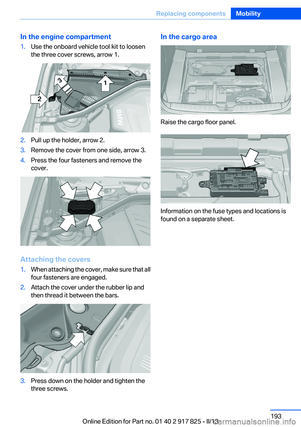
In the engine compartment1.Use the onboard vehicle tool kit to loosen
the three cover screws, arrow 1.2.Pull up the holder, arrow 2.3.Remove the cover from one side, arrow 3.4.Press the four fasteners and remove the
cover.
Attaching the covers
1.When attaching the cover, make sure that all
four fasteners are engaged.2.Attach the cover under the rubber lip and
then thread it between the bars.3.Press down on the holder and tighten the
three screws.In the cargo area
Raise the cargo floor panel.
Information on the fuse types and locations is
found on a separate sheet.
Seite 193Replacing componentsMobility193
Online Edition for Part no. 01 40 2 917 825 - II/13
Page 195 of 220

▷The LED flashes when a connection to the
BMW Response Center has been estab‐
lished.
When the emergency request is received at
the BMW Response Center, the BMW Re‐
sponse Center contacts you and takes fur‐
ther steps to help you.
Even if you are unable to respond, the BMW
Response Center can take further steps to
help you under certain circumstances.
For this purpose, data that are used to de‐
termine the necessary rescue measures,
such as the current position of the vehicle if
it can be established, are transmitted to the
BMW Response Center.▷If the LED is flashing but the BMW Response
Center cannot be heard on the hands-free
system, the hands-free system may be mal‐
functioning. However, the BMW Response
Center may still be able to hear you.
Initiating an Emergency Request
automatically
Under certain conditions, an Emergency Re‐
quest is automatically initiated immediately after
a severe accident. Automatic Collision Notifica‐
tion is not affected by pressing the SOS button.
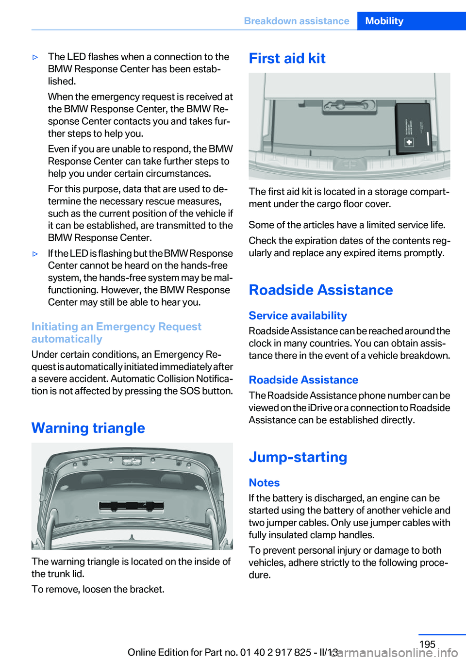
Warning triangle
The warning triangle is located on the inside of
the trunk lid.
To remove, loosen the bracket.
First aid kit
The first aid kit is located in a storage compart‐
ment under the cargo floor cover.
Some of the articles have a limited service life.
Check the expiration dates of the contents reg‐
ularly and replace any expired items promptly.
Roadside Assistance
Service availability
Roadside Assistance can be reached around the
clock in many countries. You can obtain assis‐
tance there in the event of a vehicle breakdown.
Roadside Assistance
The Roadside Assistance phone number can be
viewed on the iDrive or a connection to Roadside
Assistance can be established directly.
Jump-starting
Notes
If the battery is discharged, an engine can be
started using the battery of another vehicle and
two jumper cables. Only use jumper cables with
fully insulated clamp handles.
To prevent personal injury or damage to both
vehicles, adhere strictly to the following proce‐
dure.
Seite 195Breakdown assistanceMobility195
Online Edition for Part no. 01 40 2 917 825 - II/13
Page 196 of 220

Do not touch live parts
To avoid the risk of potentially fatal injury,
always avoid all contact with electrical compo‐
nents while the engine is running.◀
Preparation1.Check whether the battery of the other ve‐
hicle has a voltage of 12 volts. This informa‐
tion can be found on the battery.2.Switch off the engine of the assisting vehi‐
cle.3.Switch off any electronic systems/power
consumers in both vehicles.
Bodywork contact between vehicles
Make sure that there is no contact be‐
tween the bodywork of the two vehicles; other‐
wise, there is the danger of short circuits.◀
Starting aid terminals Connecting order
Connect the jumper cables in the correct
order; otherwise, there is the danger of injury
from sparking.◀
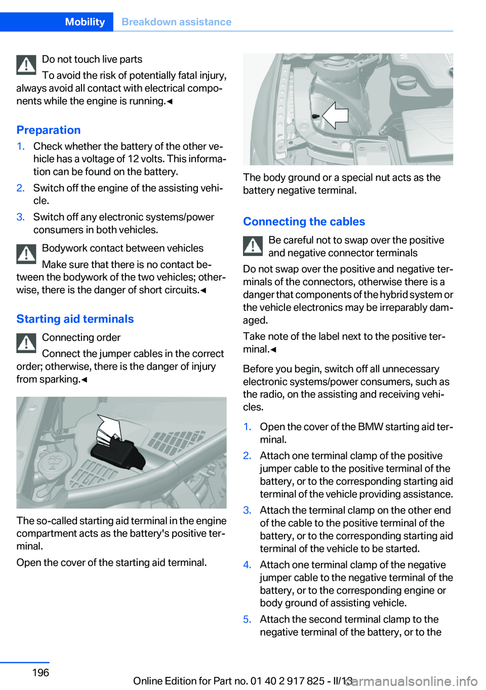
The so-called starting aid terminal in the engine
compartment acts as the battery's positive ter‐
minal.
Open the cover of the starting aid terminal.
The body ground or a special nut acts as the
battery negative terminal.
Connecting the cables Be careful not to swap over the positive
and negative connector terminals
Do not swap over the positive and negative ter‐
minals of the connectors, otherwise there is a
danger that components of the hybrid system or
the vehicle electronics may be irreparably dam‐
aged.
Take note of the label next to the positive ter‐
minal.◀
Before you begin, switch off all unnecessary
electronic systems/power consumers, such as
the radio, on the assisting and receiving vehi‐
cles.
1.Open the cover of the BMW starting aid ter‐
minal.2.Attach one terminal clamp of the positive
jumper cable to the positive terminal of the
battery, or to the corresponding starting aid
terminal of the vehicle providing assistance.3.Attach the terminal clamp on the other end
of the cable to the positive terminal of the
battery, or to the corresponding starting aid
terminal of the vehicle to be started.4.Attach one terminal clamp of the negative
jumper cable to the negative terminal of the
battery, or to the corresponding engine or
body ground of assisting vehicle.5.Attach the second terminal clamp to the
negative terminal of the battery, or to theSeite 196MobilityBreakdown assistance196
Online Edition for Part no. 01 40 2 917 825 - II/13
Page 197 of 220

corresponding engine or body ground of the
vehicle to be started.
Starting the engine
Never use spray fluids to start the engine.
1.Start the engine of the assisting vehicle and
let it run for several minutes at an increased
idle speed.2.Start the engine of the vehicle being started
in the usual way.
If the first starting attempt is not successful,
wait a few minutes before making another
attempt in order to allow the discharged bat‐
tery to recharge.3.Let both engines run for several minutes.4.Disconnect the jumper cables in the reverse
order.
Check the battery and recharge if necessary.
Tow-starting and towing
Automatic transmission: transporting
your vehicle
Note
Your vehicle is not permitted to be towed.
Therefore, contact a service center in the event
of a breakdown.
Do not have the vehicle towed
Have your vehicle transported on a loading
platform only; otherwise, damage may occur.◀
Tow truck
Do not lift the vehicle
Do not lift the vehicle by the tow fitting or
body and chassis parts; otherwise, damage may
result.◀
Use the tow fitting screwed in at the front for
maneuvering the vehicle only.
Towing other vehicles
General information Light towing vehicle
The towing vehicle must not be lighter
than the vehicle being towed; otherwise, it will
not be possible to control the vehicle re‐
sponse.◀
Attaching the tow bar/tow rope correctly
Attach the tow bar or tow rope to the tow
fitting; connecting it to other vehicle parts may
cause damage.◀
▷Switch on the hazard warning system, de‐
pending on local regulations.▷If the electrical system has failed, clearly
identify the vehicle being towed by placing
a sign or a warning triangle in the rear win‐
dow.
Tow bar
The tow fittings used should be on the same
side on both vehicles.
Seite 197Breakdown assistanceMobility197
Online Edition for Part no. 01 40 2 917 825 - II/13