2013 BMW ACTIVEHYBRID3 engine
[x] Cancel search: enginePage 79 of 220
▷When a dynamic driving style is used, such
as when cornering quickly, operation of the
engine is not always ensured.
The Check Control message appears continu‐
ously below a range of approx. 30 miles/50 km.
Refuel promptly
Refuel no later than at a range of
30 miles/50 km, or operation of the engine is not
ensured and damage may occur.◀
Displaying the cruising range
1."Settings"2."Info display"3."Additional indicators"
The range is displayed in the instrument cluster.
Displays of the hybrid system
Displays in the instrument cluster
The concept
The display depends on the system's operating
condition. The following functions of the hybrid
system are shown in the instrument cluster.
▷High-voltage battery charge indicator.▷Electric driving: eDRIVE.▷Acceleration boost: ASSIST and eBOOST.▷Energy recovery: CHARGE.▷Auto Start/Stop function: READY.High-voltage battery charge indicator
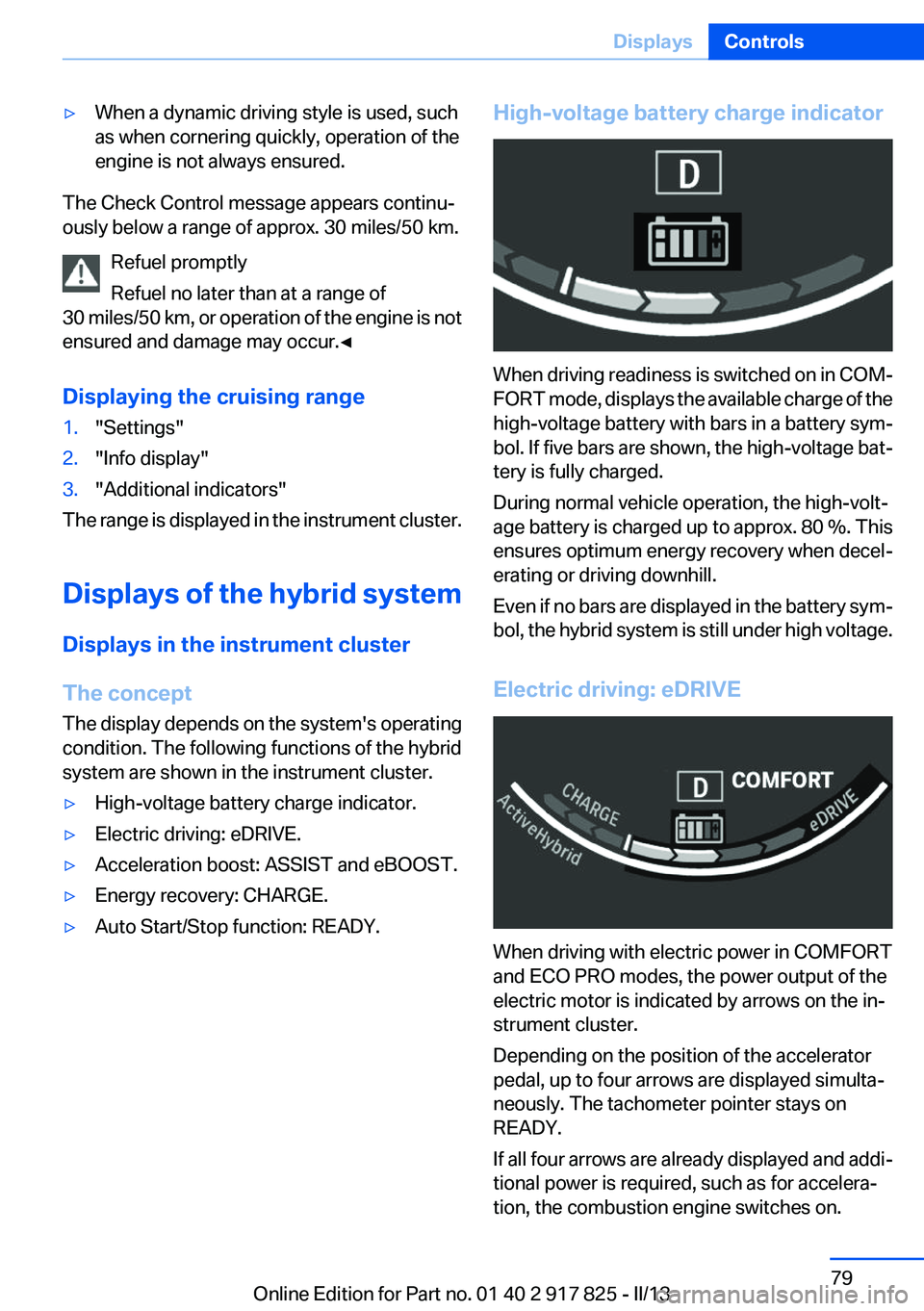
When driving readiness is switched on in COM‐
FORT mode, displays the available charge of the
high-voltage battery with bars in a battery sym‐
bol. If five bars are shown, the high-voltage bat‐
tery is fully charged.
During normal vehicle operation, the high-volt‐
age battery is charged up to approx. 80 %. This
ensures optimum energy recovery when decel‐
erating or driving downhill.
Even if no bars are displayed in the battery sym‐
bol, the hybrid system is still under high voltage.
Electric driving: eDRIVE
When driving with electric power in COMFORT
and ECO PRO modes, the power output of the
electric motor is indicated by arrows on the in‐
strument cluster.
Depending on the position of the accelerator
pedal, up to four arrows are displayed simulta‐
neously. The tachometer pointer stays on
READY.
If all four arrows are already displayed and addi‐
tional power is required, such as for accelera‐
tion, the combustion engine switches on.
Seite 79DisplaysControls79
Online Edition for Part no. 01 40 2 917 825 - II/13
Page 80 of 220
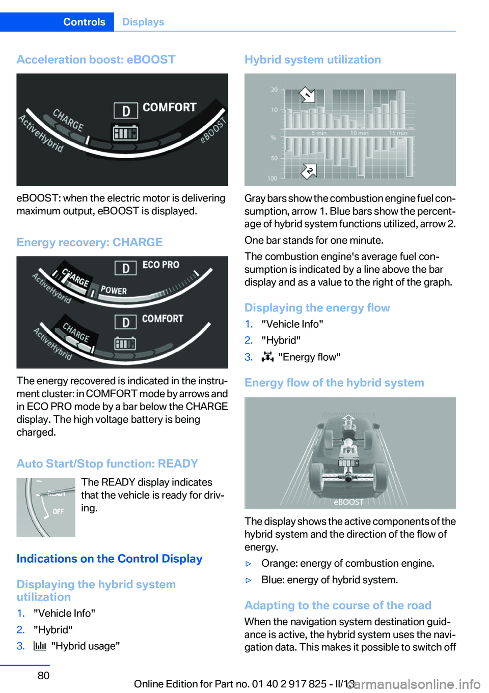
Acceleration boost: eBOOST
eBOOST: when the electric motor is delivering
maximum output, eBOOST is displayed.
Energy recovery: CHARGE
The energy recovered is indicated in the instru‐
ment cluster: in COMFORT mode by arrows and
in ECO PRO mode by a bar below the CHARGE
display. The high voltage battery is being
charged.
Auto Start/Stop function: READY The READY display indicates
that the vehicle is ready for driv‐
ing.
Indications on the Control Display
Displaying the hybrid system
utilization
1."Vehicle Info"2."Hybrid"3. "Hybrid usage"Hybrid system utilization
Gray bars show the combustion engine fuel con‐
sumption, arrow 1. Blue bars show the percent‐
age of hybrid system functions utilized, arrow 2.
One bar stands for one minute.
The combustion engine's average fuel con‐
sumption is indicated by a line above the bar
display and as a value to the right of the graph.
Displaying the energy flow
1."Vehicle Info"2."Hybrid"3. "Energy flow"
Energy flow of the hybrid system
The display shows the active components of the
hybrid system and the direction of the flow of
energy.
▷Orange: energy of combustion engine.▷Blue: energy of hybrid system.
Adapting to the course of the road
When the navigation system destination guid‐
ance is active, the hybrid system uses the navi‐
gation data. This makes it possible to switch off
Seite 80ControlsDisplays80
Online Edition for Part no. 01 40 2 917 825 - II/13
Page 81 of 220
the combustion engine upon reaching the des‐
tination zone even before reaching the destina‐
tion. The vehicle is powered only by the electric
motor.
The symbol indicates that the vehicle will
switch off the combustion engine when it enters
the destination zone.
Current fuel consumption
Instrument cluster Displays the current fuel con‐
sumption. You can check
whether you are currently driving
in an efficient and environmen‐
tally-friendly manner.
This display is available in the SPORT driving
mode.
Current consumption can be displayed in the
onboard computer, refer to page 84, in any
driving mode.
Service requirements
The concept
The driving distance or the time to the next
scheduled maintenance is displayed briefly after
the ignition is switched on.
The current service requirements can be read
out from the remote control by the service spe‐
cialist.
Display
Data regarding the service status or legally man‐
dated inspections of the vehicle are automati‐
cally transmitted to your service center before a
service due date.
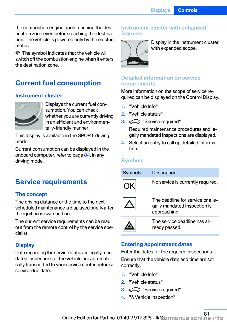
Instrument cluster with enhanced
features
Display in the instrument cluster
with expanded scope.
Detailed information on service
requirements
More information on the scope of service re‐
quired can be displayed on the Control Display.1."Vehicle Info"2."Vehicle status"3. "Service required"
Required maintenance procedures and le‐
gally mandated inspections are displayed.4.Select an entry to call up detailed informa‐
tion.
Symbols
SymbolsDescriptionNo service is currently required.The deadline for service or a le‐
gally mandated inspection is
approaching.The service deadline has al‐
ready passed.
Entering appointment dates
Enter the dates for the required inspections.
Ensure that the vehicle date and time are set
correctly.
1."Vehicle Info"2."Vehicle status"3. "Service required"4."§ Vehicle inspection"Seite 81DisplaysControls81
Online Edition for Part no. 01 40 2 917 825 - II/13
Page 85 of 220
Information at a glance
Repeatedly pressing the button on the turn sig‐
nal lever calls up the following information on the
info display:▷Range.▷Average fuel consumption.▷Current fuel consumption.▷Average speed.▷Date.▷Speed limit detection.▷Time of arrival.
When destination guidance is activated in
the navigation system.▷Distance to destination.
When destination guidance is activated in
the navigation system.▷Arrow view of navigation system.
When destination guidance is activated in
the navigation system.
When the arrow view in the Head-up Display
is inactive.▷ECO PRO bonus range.▷Charge state of the high-voltage battery as
a percentage.
Adjusting the info display
You can select what information from the on‐
board computer is to be displayed on the info
display of the instrument cluster.
1."Settings"2."Info display"3.Select the desired displays.
Information in detail
Range
Displays the estimated cruising range available
with the remaining fuel.
It is calculated based on your driving style over
the last 20 miles/30 km.
If there is only enough fuel left for less than
45 miles/80 km, the color of the display changes.
Average fuel consumption
This is calculated for the period during which the
engine is running.
The average fuel consumption is calculated for
the distance traveled since the last reset by the
onboard computer.
Average speed
Periods in which the vehicle is parked with the
engine manually stopped do not enter into the
calculation of the average speed.
Resetting average values
Press and hold the computer button on the turn
signal lever.
Distance to destination
The distance remaining to the destination is dis‐
played if a destination is entered in the naviga‐
tion system before the trip is started.
The distance to the destination is adopted au‐
tomatically.
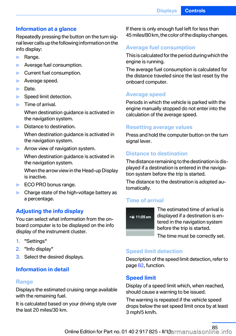
Time of arrival The estimated time of arrival is
displayed if a destination is en‐
tered in the navigation system
before the trip is started.
The time must be correctly set.
Speed limit detection
Description of the speed limit detection, refer to
page 82, function.
Speed limit
Display of a speed limit which, when reached,
should cause a warning to be issued.
The warning is repeated if the vehicle speed
drops below the set speed limit once by at least
3 mph/5 km/h.Seite 85DisplaysControls85
Online Edition for Part no. 01 40 2 917 825 - II/13
Page 90 of 220

LampsVehicle equipment
All standard, country-specific and optional
equipment that is offered in the model series is
described in this chapter. Therefore, equipment
is also described that is not available in a vehicle,
e. g., because of the selected optional equip‐
ment or country variant. This also applies for
safety-related functions and systems.
At a glance1Rear fog lamps2Front fog lamps3Automatic headlamp control, Adaptive Light
Control, High-beam Assistant, Welcome
lamps, Daytime running lights4Lamps off, daytime running lights5Parking lamps, daytime running lights6Low beams, welcome lamps, High-beam
Assistant7Instrument lighting
Parking lamps/low beams,
headlamp control
General information
Switch position: 0,
,
If the driver door is opened with the ignition
switched off, the exterior lighting is automati‐
cally switched off at these switch settings.
Parking lamps
Switch position
: the vehicle lamps light
up on all sides, e.g., for parking.
Do not use the parking lamps for extended pe‐
riods; otherwise, the battery may become dis‐
charged and it would then be impossible to start
the engine.
When parking, it is preferable to switch on the
one-sided roadside parking lamps, refer to
page 91.
Low beams
Switch position
with the ignition switched
on: the low beams light up.
Welcome lamps
When parking the vehicle, leave the switch in
position
or : the parking and interior
lamps light up briefly when the vehicle is un‐
locked.
Activating/deactivating
1."Settings"2."Lighting"3."Welcome lights"
The setting is stored for the remote control cur‐
rently in use.
Seite 90ControlsLamps90
Online Edition for Part no. 01 40 2 917 825 - II/13
Page 99 of 220

One wheel is yellow
A flat tire or major drop in inflation pressure in
the indicated tire.
All wheels are yellow
A flat tire or major drop in inflation pressure in
several tires.
Wheels, gray
The system cannot detect a flat tire. Reasons for
this may be:▷The system is being reset.▷Malfunction.
Carry out reset
Reset the system after each correction of the
tire inflation pressure and after every tire or
wheel change.
1."Vehicle Info"2."Vehicle status"3. "Reset"4.Start the engine - do not drive away.5.Carry out the reset with "Reset".6.Drive away.
The tires are shown in gray and the status is dis‐
played.
After driving faster than 19 mph/30 km/h for a
short period, the tire inflation pressures set are
accepted as reference values. The reset is com‐
pleted automatically during driving. After suc‐
cessful completion of the reset, the tires appear
in green on the Control Display and "TPM
active" is displayed.
The trip can be interrupted at any time. If you
drive away again, the reset resumes automati‐
cally.
Low tire pressure message The yellow warning lamp lights up. A
Check Control message is displayed.
▷There is a flat tire or a major loss in tire in‐
flation pressure.▷A reset of the system was not carried out af‐
ter a wheel was changed. The system there‐
fore issues a warning based on the tire pres‐
sures before the last reset.1.Reduce your speed and stop cautiously.
Avoid sudden braking and steering maneu‐
vers.2.Check whether the vehicle is fitted with reg‐
ular tires or run-flat tires.
Run-flat tires, refer to page 175, are labeled
with a circular symbol containing the letters
RSC marked on the tire sidewall.
Do not continue driving without run-flat
tires
Do not continue driving if the vehicle is not
equipped with run-flat tires; continued driving
may result in serious accidents.◀
When a low inflation pressure is indicated, DSC
Dynamic Stability Control is switched on if nec‐
essary.
Actions in the event of a flat tire
Normal tires
1.Identify the damaged tire.
Do this by checking the air pressure in all
four tires.
If the tire inflation pressure in all four tires is
correct, it is possible that a reset was not
carried out for the Tire Pressure Monitor. In
that case, carry out a reset.
If an identification is not possible, please
contact the service center.2.Rectify the flat tire.
Use of tire sealant, e.g., the Mobility System,
may damage the TPM wheel electronics. In
this case, have the electronics checked at
the next opportunity and have them re‐
placed if necessary.Seite 99SafetyControls99
Online Edition for Part no. 01 40 2 917 825 - II/13
Page 102 of 220

2."Vehicle status"3. "Flat Tire Monitor"
The status is displayed.
Initialization
The initialization process adopts the set inflation
tire pressures as reference values for the detec‐
tion of a flat tire. Initialization is started by con‐
firming the inflation pressures.
Do not initialize the system when driving with
snow chains.
1."Vehicle Info"2."Vehicle status"3. "Reset"4.Start the engine - do not drive away.5.Start the initialization with "Reset".6.Drive away.
The initialization is completed while driving,
which can be interrupted at any time.
The initialization automatically continues when
driving resumes.
Indication of a flat tire The yellow warning lamp lights up. A
Check Control message is displayed.
There is a flat tire or a major loss in tire
inflation pressure.
1.Reduce your speed and stop cautiously.
Avoid sudden braking and steering maneu‐
vers.2.Check whether the vehicle is fitted with reg‐
ular tires or run-flat tires.
Run-flat tires, refer to page 175, are labeled
with a circular symbol containing the letters
RSC marked on the tire sidewall.
Do not continue driving without run-flat
tires
Do not continue driving if the vehicle is not
equipped with run-flat tires; continued driving
may result in serious accidents.◀
When a flat tire is indicated, DSC Dynamic Sta‐
bility Control is switched on if necessary.
System limits Sudden tire damage
Sudden serious tire damage caused by
external influences cannot be indicated in ad‐
vance.◀
A natural, even pressure loss in all four tires can‐
not be detected. Therefore, check the tire infla‐
tion pressure regularly.
The system could be delayed or malfunction in
the following situations:▷When the system has not been initialized.▷When driving on a snowy or slippery road
surface.▷Sporty driving style: slip in the drive wheels,
high lateral acceleration.▷When driving with snow chains.
Actions in the event of a flat tire
Normal tires
1.Identify the damaged tire.
Do this by checking the air pressure in all
four tires.
If the tire inflation pressure in all four tires is
correct, the Flat Tire Monitor may not have
been initialized. In this case, initialize the
system.
If an identification is not possible, please
contact the service center.2.Rectify the flat tire.
Run-flat tires
Maximum speed
You can continue driving with a damaged tire at
speeds up to 50 mph/80 km/h.
Seite 102ControlsSafety102
Online Edition for Part no. 01 40 2 917 825 - II/13
Page 108 of 220
A Check Control message is displayed when the
system is not fully functional.
For US owners only
The transmitter and receiver units comply with
part 15 of the FCC/Federal Communication
Commission regulations. Operation is governed
by the following:
FCC ID:▷NBG009014A.
Compliance statement:
This device complies with part 15 of the FCC
Rules. Operation is subject to the following two
conditions:
▷This device may not cause harmful interfer‐
ence, and▷this device must accept any interference re‐
ceived, including interference that may
cause undesired operation.
Any unauthorized modifications or changes to
these devices could void the user's authority to
operate this equipment.
Brake force display
The concept
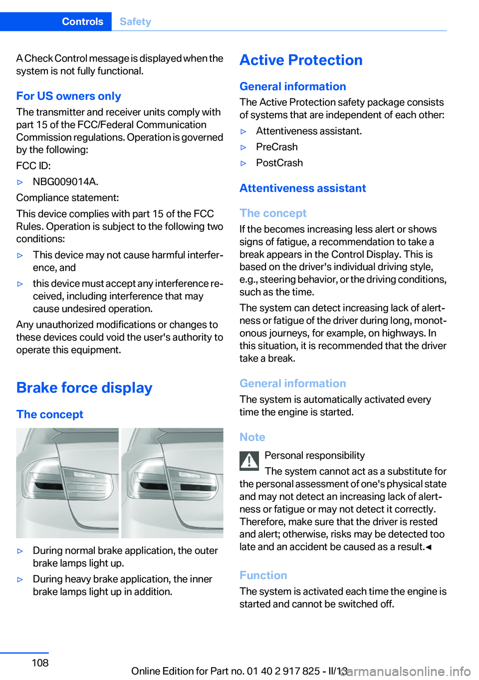
▷During normal brake application, the outer
brake lamps light up.▷During heavy brake application, the inner
brake lamps light up in addition.Active Protection
General information
The Active Protection safety package consists
of systems that are independent of each other:▷Attentiveness assistant.▷PreCrash▷PostCrash
Attentiveness assistant
The concept
If the becomes increasing less alert or shows
signs of fatigue, a recommendation to take a
break appears in the Control Display. This is
based on the driver's individual driving style,
e.g., steering behavior, or the driving conditions,
such as the time.
The system can detect increasing lack of alert‐
ness or fatigue of the driver during long, monot‐
onous journeys, for example, on highways. In
this situation, it is recommended that the driver
take a break.
General information
The system is automatically activated every
time the engine is started.
Note Personal responsibility
The system cannot act as a substitute for
the personal assessment of one's physical state
and may not detect an increasing lack of alert‐
ness or fatigue or may not detect it correctly.
Therefore, make sure that the driver is rested
and alert; otherwise, risks may be detected too
late and an accident be caused as a result.◀
Function
The system is activated each time the engine is
started and cannot be switched off.
Seite 108ControlsSafety108
Online Edition for Part no. 01 40 2 917 825 - II/13