2013 BMW ACTIVEHYBRID3 warning light
[x] Cancel search: warning lightPage 113 of 220

This results in a sporty steering response. In ad‐
dition, it becomes easier to steer during parking
and maneuvering.
Driving Dynamics Control
The concept
The Driving Dynamics Control can be used to
adjust the certain characteristics of the vehicle.
Various programs can be selected for this pur‐
pose. The Driving Dynamics Control and the
DSC OFF buttons can each be used to activate
a program.
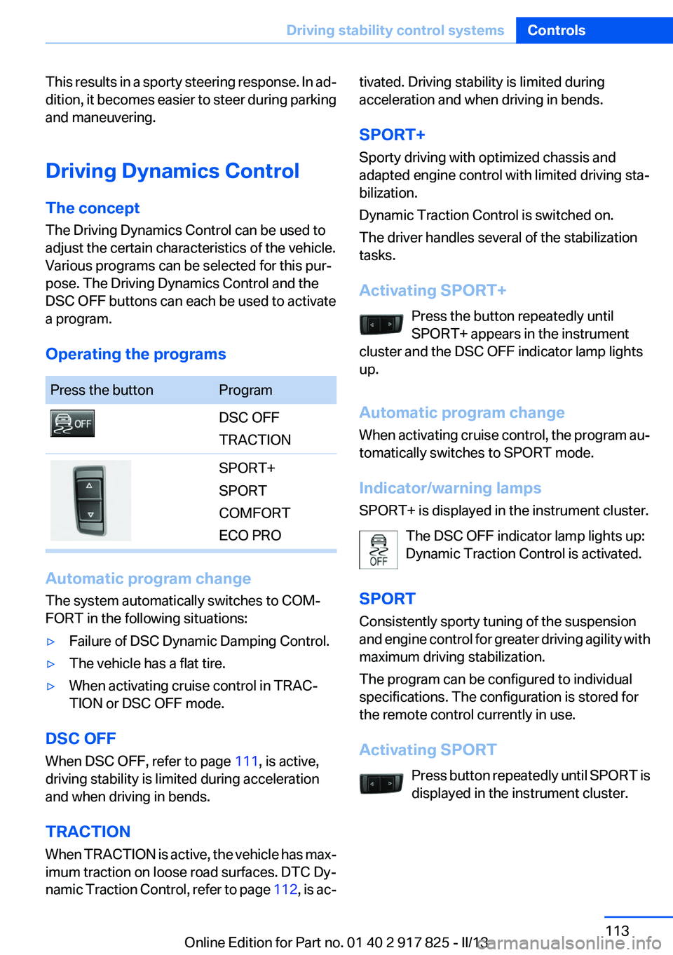
Operating the programsPress the buttonProgramDSC OFF
TRACTIONSPORT+
SPORT
COMFORT
ECO PRO
Automatic program change
The system automatically switches to COM‐
FORT in the following situations:
▷Failure of DSC Dynamic Damping Control.▷The vehicle has a flat tire.▷When activating cruise control in TRAC‐
TION or DSC OFF mode.
DSC OFF
When DSC OFF, refer to page 111, is active,
driving stability is limited during acceleration
and when driving in bends.
TRACTION
When TRACTION is active, the vehicle has max‐
imum traction on loose road surfaces. DTC Dy‐
namic Traction Control, refer to page 112, is ac‐
tivated. Driving stability is limited during
acceleration and when driving in bends.
SPORT+
Sporty driving with optimized chassis and
adapted engine control with limited driving sta‐
bilization.
Dynamic Traction Control is switched on.
The driver handles several of the stabilization
tasks.
Activating SPORT+ Press the button repeatedly until
SPORT+ appears in the instrument
cluster and the DSC OFF indicator lamp lights
up.
Automatic program change
When activating cruise control, the program au‐
tomatically switches to SPORT mode.
Indicator/warning lamps
SPORT+ is displayed in the instrument cluster.
The DSC OFF indicator lamp lights up:
Dynamic Traction Control is activated.
SPORT
Consistently sporty tuning of the suspension
and engine control for greater driving agility with
maximum driving stabilization.
The program can be configured to individual
specifications. The configuration is stored for
the remote control currently in use.
Activating SPORT Press button repeatedly until SPORT is
displayed in the instrument cluster.Seite 113Driving stability control systemsControls113
Online Edition for Part no. 01 40 2 917 825 - II/13
Page 118 of 220

The stored speed is reached and maintained.
Displays in the instrument cluster
Indicator lamp Depending on how the vehicle is equip‐
ped, the indicator lamp in the instrument
cluster indicates whether the system is
switched on.
Desired speed▷The marking lights up green:
the system is active.▷The marking lights up or‐
ange: the system has been
interrupted.▷The marking does not light up: the system is
switched off.
Brief status display
Selected desired speed.
If --- appears briefly on the display for Check
Control messages, it is possible that the system
requirements for operation are currently not
met.
PDC Park Distance Control
The concept
PDC supports you when parking. Objects that
you are approaching slowly in front of or behind
your vehicle are indicated with:
▷Signal tones.▷Visual display.
General information
Measurements are made by ultrasound sensors
in the bumpers.
The range is approx. 6 ft/2 m.
An acoustic warning is first given:▷By the front middle sensors and the two cor‐
ner sensors at approx. 24 in/60 cm.▷By the rear middle sensors at approx.
5 ft/1.50 m.
Notes
Check the traffic situation as well
PDC cannot serve as a substitute for the
driver's personal judgment of the traffic situa‐
tion. Check the traffic situation around the vehi‐
cle with your own eyes. Otherwise, an accident
could result from road users or objects located
outside of the PDC detection range.
Loud noises from outside and inside the vehicle
may prevent you from hearing the PDC's signal
tone.◀
Avoid driving quickly with PDC
Avoid approaching an object quickly.
Avoid driving away quickly while PDC is not yet
active.
For technical reasons, the system may other‐
wise be too late in issuing a warning.◀
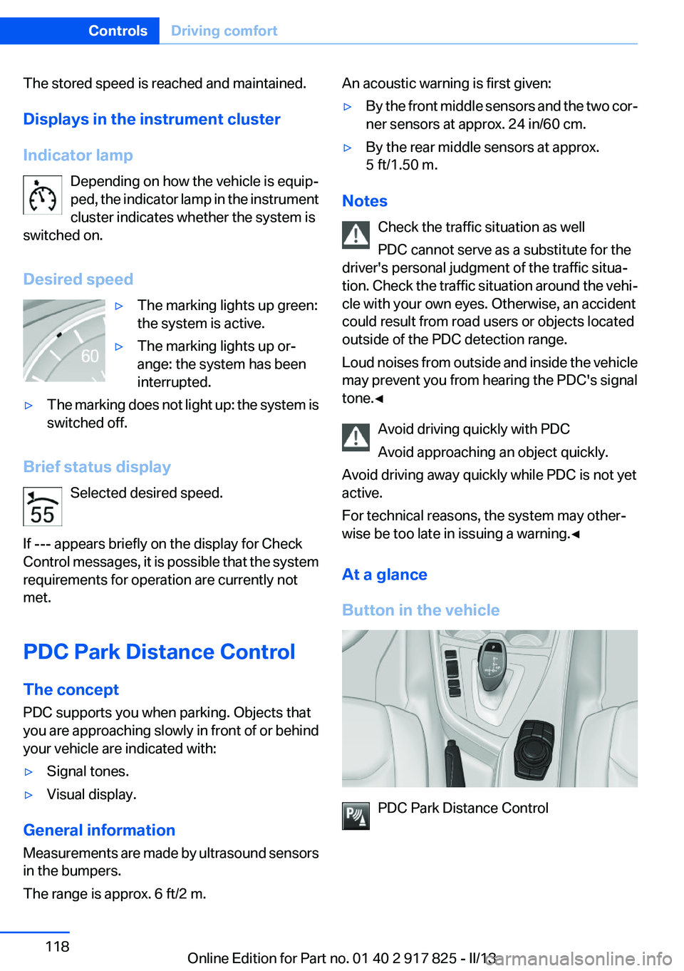
At a glance
Button in the vehicle
PDC Park Distance Control
Seite 118ControlsDriving comfort118
Online Edition for Part no. 01 40 2 917 825 - II/13
Page 119 of 220

Switching on/off
Switching on automatically
Select transmission position R with the engine
running.
Automatic deactivation during forward
travel
The system switches off when a certain driving
distance or speed is exceeded.
Switch the system back on if necessary.
Switching on/off manually Press the button.▷On: the LED lights up.▷Off: the LED goes out.
In addition to the PDC Park Distance Control, the
backup camera, refer to page 120, can be
switched on.
Switching on the backup camera via the
iDrive
With PDC activated:
"Rear view camera"
The backup camera image is displayed. The set‐
ting is stored for the remote control currently in
use.
Display
Signal tones
When approaching an object, an intermittent
tone is sounded that indicates the position of the
object. For example, if an object is detected to
the left rear of the vehicle, a signal tone sounds
from the left rear speaker.
The shorter the distance to the object becomes,
the shorter the intervals.
If the distance to a detected object is less than
approx. 10 in/25 cm, a continuous tone is
sounded.
If objects are located both in front of and behind
the vehicle, an alternating continuous signal is
sounded.
The intermittent tone is interrupted after approx.
3 seconds:▷If the vehicle stops in front of an object that
is detected by only one of the corner sen‐
sors.▷If moving parallel to a wall.
The signal tone is switched off:
▷When the vehicle moves away from an ob‐
ject by more than approx. 4 in/10 cm.▷When transmission position P is engaged.
Volume
The volume of the PDC signal can be adjusted,
refer to user's manual for Navigation, Entertain‐
ment and Communication.
The setting is stored for the remote control cur‐
rently in use.
Visual warning
The approach of the vehicle to an object can be
shown on the Control Display. Objects that are
farther away are displayed on the Control Dis‐
play before a signal tone sounds.
A display appears as soon as Park Distance
Control (PDC) is activated.
The range of the sensors is represented in col‐
ors: red, green and yellow.
If the backup camera image was selected last, it
again appears on the display. To switch to PDC:
1. "Rear view camera" Select the symbol
on the Control Display.2.Press the controller.
The setting is stored for the remote control cur‐
rently in use.
Seite 119Driving comfortControls119
Online Edition for Part no. 01 40 2 917 825 - II/13
Page 120 of 220

System limits
Limits of ultrasonic measurement
The detection of objects can reach the physical
limits of ultrasonic measurement, e.g.:▷With tow bars and trailer hitches.▷With thin or wedge-shaped objects.▷With low objects.▷With objects with corners and sharp edges.
Low objects already displayed, e.g., curbs, can
move into the blind area of the sensors before or
after a continuous tone sounds.
High, protruding objects such as ledges may not
be detected.
False warnings
PDC may issue a warning under the following
conditions even though there is no obstacle
within the detection range:
▷In heavy rain.▷When sensors are very dirty or covered in
ice.▷When sensors are covered in snow.▷On rough road surfaces.▷In large buildings with right angles and
smooth walls, e.g., in underground garages.▷In heavy exhaust.▷Due to other ultrasound sources, e.g.,
sweeping machines, high pressure steam
cleaners or neon lights.
The malfunction is signaled by a continuous
tone alternating between the front and rear
speakers. As soon as the malfunction due to
other ultrasound sources is no longer
present, the system is again fully functional.
Malfunction
A Check Control message is displayed.
The range of the sensors is shown as a shaded
area on the Control Display.
PDC has failed. Have the system checked.
To ensure full operability:▷Keep the sensors clean and free of ice.▷When using high-pressure washers, do not
spray the sensors for long periods and main‐
tain a distance of at least 12 in/30 cm.
Surround View
The concept
Surround View comprises various camera as‐
sistance systems that help the driver when park‐
ing, maneuvering, and at complex exits and in‐
tersections.
▷Backup camera, refer to page 120▷Side View, refer to page 125.▷Top View, refer to page 123.
Backup camera
The concept
The backup camera provides assistance in park‐
ing and maneuvering backwards. The area be‐
hind the vehicle is shown on the Control Display.
Notes Check the traffic situation as well
Check the traffic situation around the ve‐
hicle with your own eyes. Otherwise, an accident
could result from road users or objects located
outside the picture area of the backup camera. ◀
Seite 120ControlsDriving comfort120
Online Edition for Part no. 01 40 2 917 825 - II/13
Page 124 of 220

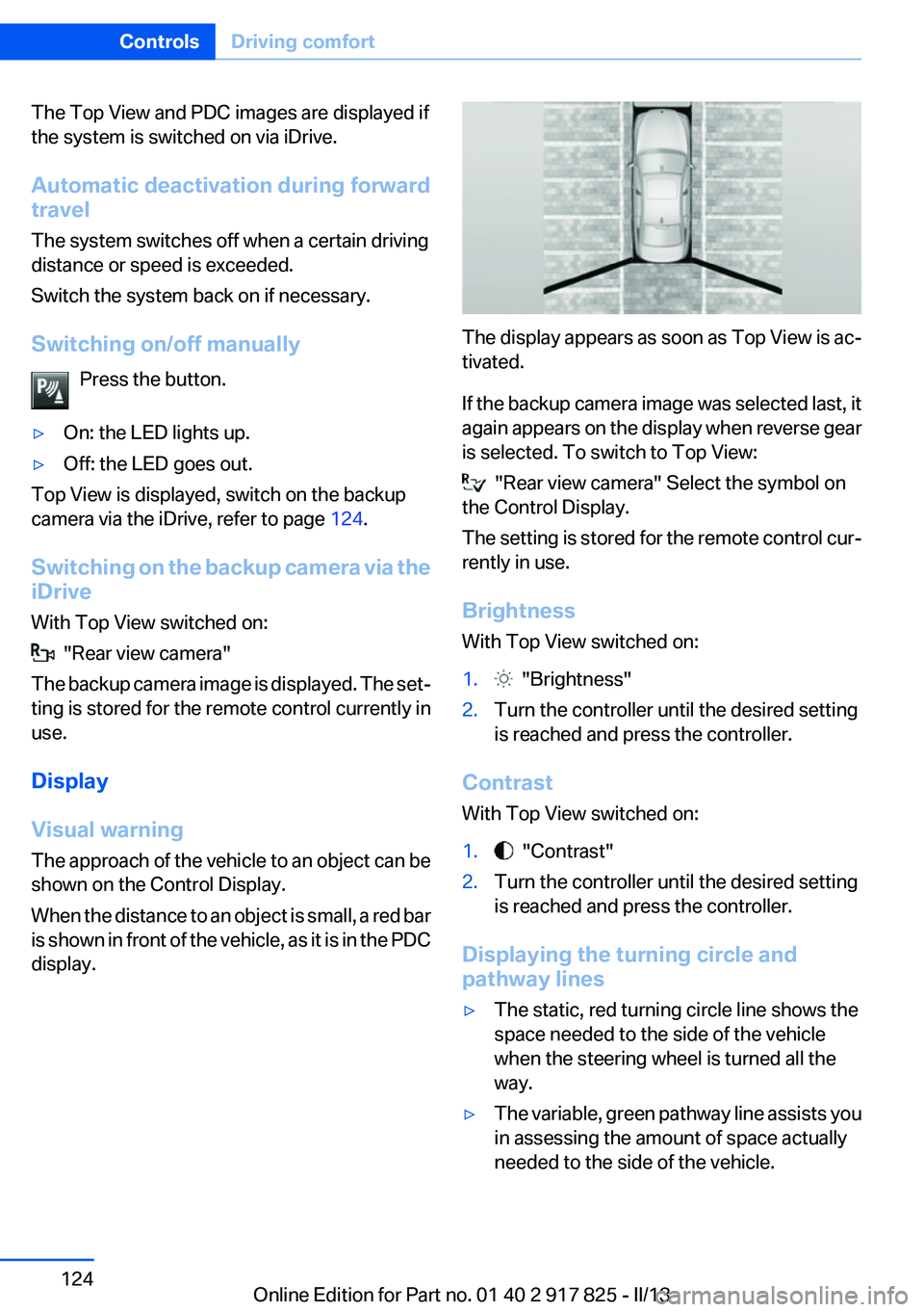
The Top View and PDC images are displayed if
the system is switched on via iDrive.
Automatic deactivation during forward
travel
The system switches off when a certain driving
distance or speed is exceeded.
Switch the system back on if necessary.
Switching on/off manually Press the button.▷On: the LED lights up.▷Off: the LED goes out.
Top View is displayed, switch on the backup
camera via the iDrive, refer to page 124.
Switching on the backup camera via the
iDrive
With Top View switched on:
"Rear view camera"
The backup camera image is displayed. The set‐
ting is stored for the remote control currently in
use.
Display
Visual warning
The approach of the vehicle to an object can be
shown on the Control Display.
When the distance to an object is small, a red bar
is shown in front of the vehicle, as it is in the PDC
display.
The display appears as soon as Top View is ac‐
tivated.
If the backup camera image was selected last, it
again appears on the display when reverse gear
is selected. To switch to Top View:
"Rear view camera" Select the symbol on
the Control Display.
The setting is stored for the remote control cur‐
rently in use.
Brightness
With Top View switched on:
1. "Brightness"2.Turn the controller until the desired setting
is reached and press the controller.
Contrast
With Top View switched on:
1. "Contrast"2.Turn the controller until the desired setting
is reached and press the controller.
Displaying the turning circle and
pathway lines
▷The static, red turning circle line shows the
space needed to the side of the vehicle
when the steering wheel is turned all the
way.▷The variable, green pathway line assists you
in assessing the amount of space actually
needed to the side of the vehicle.Seite 124ControlsDriving comfort124
Online Edition for Part no. 01 40 2 917 825 - II/13
Page 161 of 220

Configuring ECO PRO
Via the Driving Dynamics Control1.Activate ECO PRO.2."Configure ECO PRO"3.Configure the program.
Via the iDrive
1."Settings"2."ECO PRO mode"
Or
1."Settings"2."Driving mode"3."Configure ECO PRO"
Configure the program.
ECO PRO Tip
▷"ECO PRO limit:":
Set ECO Pro speed at which an ECO PRO
Tip is to be displayed.▷"ECO PRO speed warning":
A reminder is displayed if the set ECO PRO
speed is exceeded.
ECO PRO climate control
"ECO PRO climate control"
The climate control is adjusted to be fuel-effi‐
cient.
By making a slight change to the set tempera‐
ture, or adjusting the rate of heating or cooling
of the passenger compartment fuel consump‐
tion can be economized.
The outputs of the seat heater and the exterior
mirror heating are also reduced.
The exterior mirror heating is made available
when outside temperatures are very cold.
ECO PRO potential
The percentage of potential savings that can be
achieved with the current configuration is dis‐
played.
Display in the instrument cluster
ECO PRO bonus range An extension of the range can be
achieved by an adjusted driving
style.
This may be displayed as the bo‐
nus range in the instrument clus‐
ter.
The bonus range is shown in the range display.
The bonus range is automatically reset every
time the vehicle is refueled.
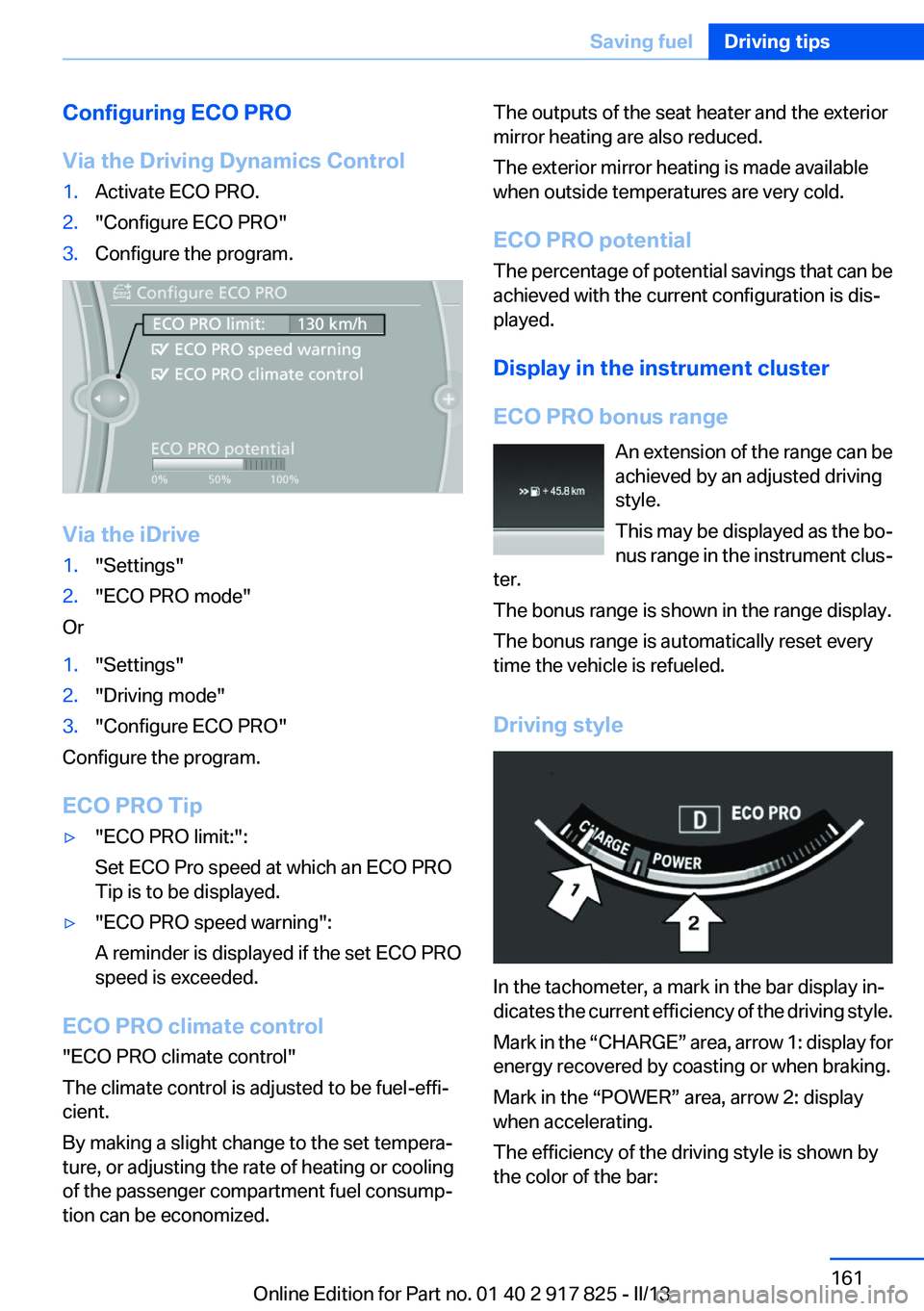
Driving style
In the tachometer, a mark in the bar display in‐
dicates the current efficiency of the driving style.
Mark in the “CHARGE” area, arrow 1: display for
energy recovered by coasting or when braking.
Mark in the “POWER” area, arrow 2: display
when accelerating.
The efficiency of the driving style is shown by
the color of the bar:
Seite 161Saving fuelDriving tips161
Online Edition for Part no. 01 40 2 917 825 - II/13
Page 179 of 220

3. "Measure engine oil level"4."Start measurement"
The oil level is checked and displayed via a scale.
Duration: approx. 1 minute.
Adding engine oil
Filler neck
When the indicator lights up in the instrument
cluster, add 1 US quart/liter of engine oil within
the next 125 miles/200 km.
Do not add too much engine oil
When too much engine oil is added, im‐
mediately have the vehicle checked, otherwise,
this may cause engine damage.◀
Protect children
Keep oil, grease, etc., out of reach of chil‐
dren and heed the warnings on the containers
to prevent health risks.◀
Oil types for refilling
Hints No oil additives
Oil additives may lead to engine damage. ◀
Viscosity grades for engine oils
When selecting an engine oil, ensure that
the engine oil belongs to one of the viscosity
grades SAE 0W-40, SAE 0W-30, SAE 5W-40,
and SAE 5W-30 or malfunctions or engine dam‐
age may occur.◀
The engine oil quality is critical for the life of the
engine.
Some types of oils in some cases are not avail‐
able in all countries.
Approved oil typesGasoline engineBMW High Performance SAE 5W-30BMW Longlife-01BMW Longlife-01 FE
Additional information about the approved
types of oils can be requested from the service
center.
Alternative oil types
If the approved engine oils are not available, up
to 1 US quart/liter of an oil with the following
specification can be added:
Gasoline engineAPI SM or superior grade specification
Oil change
An oil change should be carried out by your
service center only.
Seite 179Engine oilMobility179
Online Edition for Part no. 01 40 2 917 825 - II/13
Page 182 of 220

Socket for OBD Onboard
Diagnosis
Position
There is an OBD socket on the driver's side for
checking the primary components in the vehicle
emissions.
Emissions
▷The warning lamp lights up:
Emissions are deteriorating. Have
the vehicle checked as soon as pos‐
sible.
Canadian model: warning light indi‐
cates the engine symbol.▷The warning lamp flashes under certain cir‐
cumstances:
This indicates that there is excessive misfir‐
ing in the engine.
Reduce the vehicle speed and have the sys‐
tem checked immediately; otherwise, seri‐
ous engine misfiring within a brief period can
seriously damage emission control compo‐
nents, in particular the catalytic converter.
Fuel cap
The indicator lamp lights up.
If the fuel cap is not properly tightened,
the OBD system may conclude that fuel
vapor is escaping. If the cap is then tightened,
the display should go out in a short time.
Seite 182MobilityMaintenance182
Online Edition for Part no. 01 40 2 917 825 - II/13