2013 BMW 740LI service
[x] Cancel search: servicePage 108 of 243
Actions in the event of a flat tire
Normal tires1.Identify the damaged tire.
Do this by checking the air pressure in all
four tires.
If the tire inflation pressure in all four tires is
correct, the Tire Pressure Monitor may not
have been initialized. In this case, initialize
the system.
If an identification is not possible, please
contact the service center.2.Rectify the flat tire.
Use of tire sealant, e.g., the Mobility System,
may damage the TPM wheel electronics. In
this case, have the electronics checked at
the next opportunity and have them re‐
placed if necessary.
Run-flat tires
Maximum speed
You can continue driving with a damaged tire at
speeds up to 50 mph/80 km/h.
Continued driving with a flat tire
If continuing to drive with a damaged tire:
1.Avoid sudden braking and steering maneu‐
vers.2.Do not exceed a speed of 50 mph/80 km/h.3.Check the air pressure in all four tires at the
next opportunity.
If the tire inflation pressure in all four tires is
correct, the Tire Pressure Monitor may not
have been initialized. In this case, initialize
the system.
Possible driving distance with complete loss of
tire inflation pressure:
The possible driving distance after a loss of tire
inflation pressure depends on the cargo load
and the driving style and conditions.
For a vehicle containing an average load, the
possible driving distance is approx.
50 miles/80 km.
When the vehicle is driven with a damaged tire,
its handling characteristics change, e.g., re‐
duced lane stability during braking, a longer
braking distance, and altered self-steering
properties. Adjust your driving style accord‐
ingly. Avoid abrupt steering maneuvers or driv‐
ing over obstacles, e.g., curbs, potholes, etc.
Because the possible driving distance depends
on how the vehicle is used during the trip, the
actual distance may be smaller or greater de‐
pending on the driving speed, road conditions,
external temperature, cargo load, etc.
Continued driving with a flat tire
Drive moderately and do not exceed a
speed of 50 mph/80 km/h.
A loss of tire inflation pressure results in a
change in the handling characteristics, e.g., re‐
duced lane stability during braking, a longer
braking distance and altered self-steering prop‐
erties.◀
Final tire failure
Vibrations or loud noises while driving can
indicate the final failure of the tire. Reduce speed
and stop; otherwise, pieces of the tire could
come loose and cause an accident. Do not con‐
tinue driving, and contact your service center. ◀
Message when the system was not
reset
A Check Control message is displayed.
The system detected a wheel change but was
not reset.
Warnings regarding the current tire inflation
pressure are not reliable.
Check the tire inflation pressure and reset the
system.Seite 108ControlsSafety108
Online Edition for Part no. 01 40 2 916 693 - X/12
Page 109 of 243

MalfunctionThe yellow warning lamp flashes and
then lights up continuously. A Check
Control message is displayed. No flat
tire can be detected.
Display in the following situations:▷A wheel without TPM electronics is fitted:
have the service center check it if necessary.▷Malfunction: have the system checked by
your service center.▷TPM could not be fully reset. Reset the sys‐
tem again.▷Disturbance by systems or devices with the
same radio frequency: after leaving the area
of the disturbance, the system automatically
becomes active again.
Declaration according to NHTSA/
FMVSS 138 Tire Pressure Monitoring
System
Each tire, including the spare (if provided)
should be checked monthly when cold and in‐
flated to the inflation pressure recommended by
the vehicle manufacturer on the vehicle placard
or tire inflation pressure label. (If your vehicle has
tires of a different size than the size indicated on
the vehicle placard or tire inflation pressure la‐
bel, you should determine the proper tire infla‐
tion pressure for those tires.) As an added safety
feature, your vehicle has been equipped with a
tire pressure monitoring system (TPMS) that il‐
luminates a low tire pressure telltale when one
or more of your tires is significantly under-in‐
flated. Accordingly, when the low tire pressure
telltale illuminates, you should stop and check
your tires as soon as possible, and inflate them
to the proper pressure. Driving on a significantly
under-inflated tire causes the tire to overheat
and can lead to tire failure. Under-inflation also
reduces fuel efficiency and tire tread life, and
may affect the vehicle's handling and stopping
ability. Please note that the TPMS is not a sub‐
stitute for proper tire maintenance, and it is the
driver's responsibility to maintain correct tire
pressure, even if under-inflation has not reached
the level to trigger illumination of the TPMS low
tire pressure telltale. Your vehicle has also been
equipped with a TPMS malfunction indicator to
indicate when the system is not operating prop‐
erly. The TPMS malfunction indicator is com‐
bined with the low tire pressure telltale. When
the system detects a malfunction, the telltale will
flash for approximately one minute and then re‐
main continuously illuminated. This sequence
will continue upon subsequent vehicle start-ups
as long as the malfunction exists. When the mal‐
function indicator is illuminated, the system may
not be able to detect or signal low tire pressure
as intended. TPMS malfunctions may occur for
a variety of reasons, including the installation of
replacement or alternate tires or wheels on the
vehicle that prevent the TPMS from functioning
properly. Always check the TPMS malfunction
telltale after replacing one or more tires or
wheels on your vehicle to ensure that the re‐
placement or alternate tires and wheels allow
the TPMS to continue to function properly.
Intelligent Safety
The concept
Depending on how the vehicle is equipped, In‐
telligent Safety consists of one or more of the
following systems, which can help to avoid an
imminent collision. These systems are switched
on automatically every time the engine is started
using the Start/Stop button:▷Collision warning with braking function, re‐
fer to page 112▷Night Vision with pedestrian detection, refer
to page 114.
Note
Personal responsibility
The system does not serve as a substitute
for the driver's personal judgment of the traffic
situation.
Seite 109SafetyControls109
Online Edition for Part no. 01 40 2 916 693 - X/12
Page 127 of 243

The warning lamp lights up. A Check
Control message is displayed.1.With the engine running, turn the steering
wheel all the way to the left and right several
times in a uniform manner until the warning
lamp disappears.2.Have the system checked if the warning
lamp does not go out after moving the steer‐
ing wheel approx. 6 times or if the steering
wheel is at an angle.
Using snow chains
Ensure that the rear axle steering is deactivated
when using snow chains, refer to page 200.
Programs
The system offers several different programs.
The programs can be selected via the Driving
Dynamics Control, refer to page 127.
SPORT
Consistently sporty tuning of the Integral Active
Steering for greater driving agility.
COMFORT
Balanced tuning between the COMFORT+ and
SPORT programs.
COMFORT+
Consistently comfort-oriented tuning of the In‐
tegral Active Steering for optimal traveling com‐
fort.
Malfunction
In the event of a malfunction, the steering wheel
must be turned further, while the vehicle re‐
sponds more sensitively to steering wheel
movements in the higher speed range.
The stability-enhancing intervention may be de‐
activated.
Proceed cautiously and drive defensively.
Have the system checked.
Self-leveling suspension
The concept
The self-leveling suspension keeps the vehicle
height and ground clearance constant. The
height of the vehicle at the rear axle is main‐
tained at a predefined level under all load con‐
ditions.
The system ensures consistent comfort by
keeping spring travel constant in all driving sit‐
uations.
Malfunction
A Check Control message is displayed. A mal‐
function has occurred in the self-leveling sus‐
pension. Vehicle handling may be altered and
driving comfort may be noticeably reduced. Visit
your nearest service center.
Driving Dynamics Control
The concept
The Driving Dynamics Control can be used to
adjust the driving dynamics of the vehicle. For
this purpose various programs are available for
selection that are activated via the two buttons
of the Driving Dynamics Control and the DSC
OFF-button.
Operating the programsPress the buttonProgramDSC OFF
TRACTIONSPORT+
SPORT
COMFORT
COMFORT+
ECO PROSeite 127Driving stability control systemsControls127
Online Edition for Part no. 01 40 2 916 693 - X/12
Page 152 of 243

The basic setting can be adjusted manually.1."Settings"2."Head-Up Display"3."Brightness"4.Turn the controller.
The brightness is adjusted.
When the low beams are switched on, the
brightness of the Head-up Display can be addi‐
tionally influenced using the instrument lighting,
refer to page 98.
The setting is stored for the remote control cur‐
rently in use.
Adjusting the height
1."Settings"2."Head-Up Display"3."Height"4.Turn the controller.
The height is adjusted.
The setting is stored for the remote control cur‐
rently in use.
Setting the rotation
1."Settings"2."Head-Up Display"3."Rotation"4.Turn the controller.
Rotation is set.
The setting is stored for the remote control cur‐
rently in use.
Special windshield
The windshield is part of the system.
The shape of the windshield makes it possible
to display a precise image.
A film in the windshield prevents double images
from being displayed.
Therefore, have the special windshield replaced
by a service center only.
Distance information
The concept
The system displays a symbol in the Head-up
Display to indicate that the distance behind the
vehicle in front is not sufficient.
General information
The distance is determined by the radar sensor
of the Active Cruise Control.
Notes Personal responsibility
The display does not relieve the driver of
the responsibility to adapt his or her distance
and driving style to the traffic conditions. Main‐
tain the prescribed safety distance.◀
At a glance
Radar sensor
A dirty or covered sensor may hinder the detec‐
tion of vehicles.
▷If necessary, clean the radar sensor. Re‐
move layers of snow and ice carefully.▷Do not cover the view field of the radar sen‐
sor.
Switching on
1.Switch on Head-up Display, refer to
page 151.2."Distance info"Display in the Head-up Dis‐
play, refer to page 151Seite 152ControlsDriving comfort152
Online Edition for Part no. 01 40 2 916 693 - X/12
Page 161 of 243
Interior equipmentVehicle equipment
All standard, country-specific and optional
equipment that is offered in the model series is
described in this chapter. Therefore, equipment
is also described that is not available in a vehicle,
e. g., because of the selected optional equip‐
ment or country variant. This also applies for
safety-related functions and systems.
Integrated universal remote
control
The concept
The integrated universal remote control can op‐
erate up to 3 functions of remote-controlled sys‐
tems such as garage door drives or lighting sys‐
tems. The integrated universal remote control
replaces up to 3 different hand-held transmit‐
ters. To operate the remote control, the buttons
on the interior rearview mirror must be program‐
med with the desired functions. The hand-held
transmitter for the particular system is required
in order to program the remote control.
During programming
During programming and before activat‐
ing a device using the integrated universal re‐
mote control, ensure that there are no people,
animals, or objects in the range of movement of
the remote-controlled device; otherwise, there
is a risk of injury or damage.
Also follow the safety instructions of the hand-
held transmitter.◀
Before selling the vehicle, delete the stored
functions for the sake of security.
Compatibility If this symbol is printed on the packaging
or in the instructions of the system to be
controlled, the system is generally com‐patible with the integrated universal remote
control.
If you have any questions, please contact:▷Your service center.▷www.homelink.com on the Internet.
HomeLink is a registered trademark of Johnson
Controls, Inc.
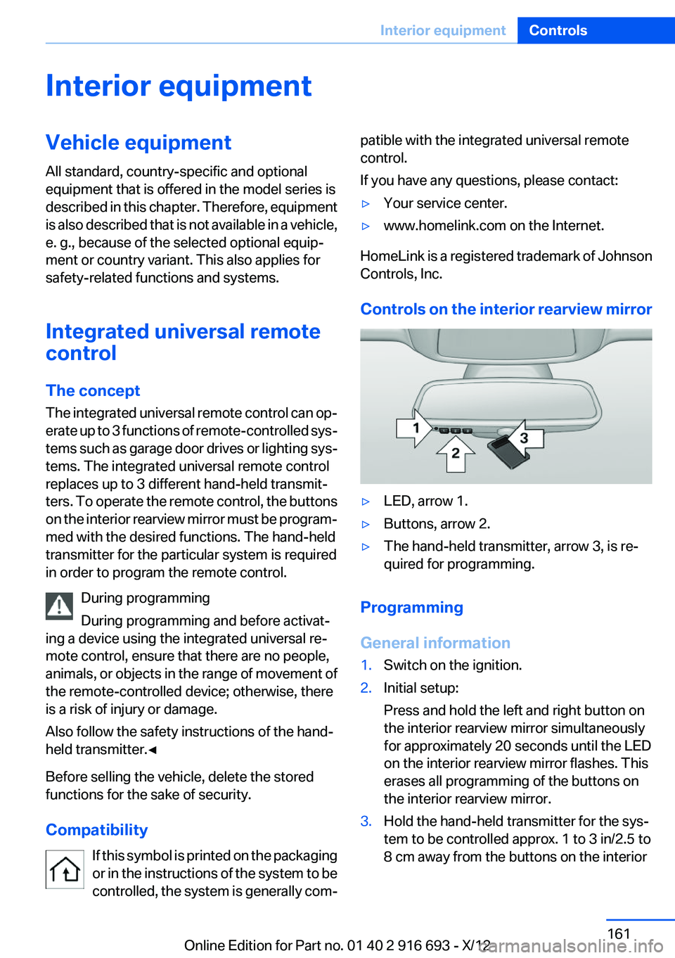
Controls on the interior rearview mirror
▷LED, arrow 1.▷Buttons, arrow 2.▷The hand-held transmitter, arrow 3, is re‐
quired for programming.
Programming
General information
1.Switch on the ignition.2.Initial setup:
Press and hold the left and right button on
the interior rearview mirror simultaneously
for approximately 20 seconds until the LED
on the interior rearview mirror flashes. This
erases all programming of the buttons on
the interior rearview mirror.3.Hold the hand-held transmitter for the sys‐
tem to be controlled approx. 1 to 3 in/2.5 to
8 cm away from the buttons on the interiorSeite 161Interior equipmentControls161
Online Edition for Part no. 01 40 2 916 693 - X/12
Page 166 of 243
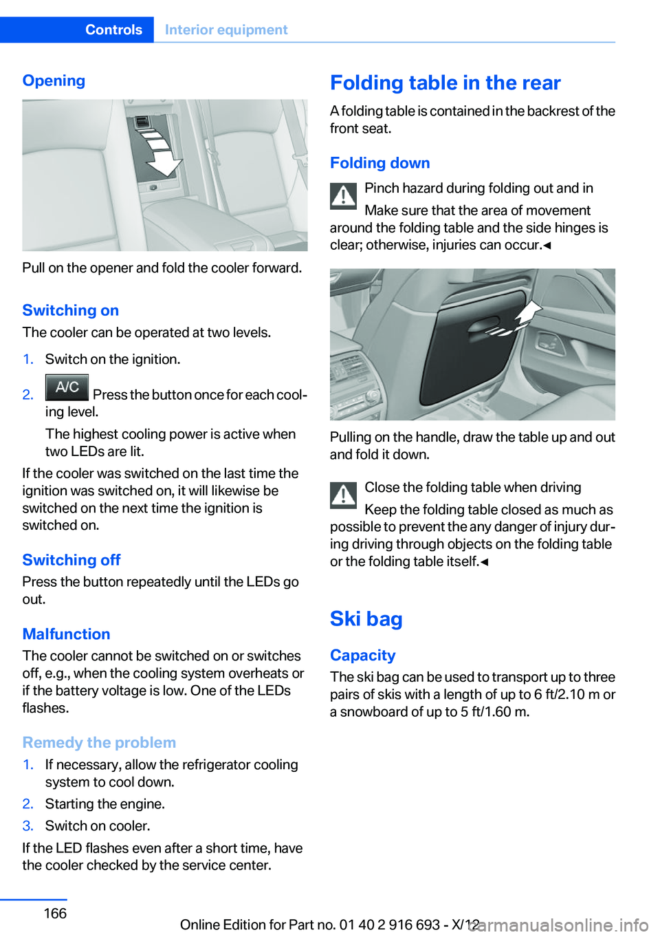
Opening
Pull on the opener and fold the cooler forward.
Switching on
The cooler can be operated at two levels.
1.Switch on the ignition.2. Press the button once for each cool‐
ing level.
The highest cooling power is active when
two LEDs are lit.
If the cooler was switched on the last time the
ignition was switched on, it will likewise be
switched on the next time the ignition is
switched on.
Switching off
Press the button repeatedly until the LEDs go
out.
Malfunction
The cooler cannot be switched on or switches
off, e.g., when the cooling system overheats or
if the battery voltage is low. One of the LEDs
flashes.
Remedy the problem
1.If necessary, allow the refrigerator cooling
system to cool down.2.Starting the engine.3.Switch on cooler.
If the LED flashes even after a short time, have
the cooler checked by the service center.
Folding table in the rear
A folding table is contained in the backrest of the
front seat.
Folding down Pinch hazard during folding out and in
Make sure that the area of movement
around the folding table and the side hinges is
clear; otherwise, injuries can occur.◀
Pulling on the handle, draw the table up and out
and fold it down.
Close the folding table when driving
Keep the folding table closed as much as
possible to prevent the any danger of injury dur‐
ing driving through objects on the folding table
or the folding table itself.◀
Ski bag
Capacity
The ski bag can be used to transport up to three
pairs of skis with a length of up to 6 ft/2.10 m or
a snowboard of up to 5 ft/1.60 m.
Seite 166ControlsInterior equipment166
Online Edition for Part no. 01 40 2 916 693 - X/12
Page 167 of 243
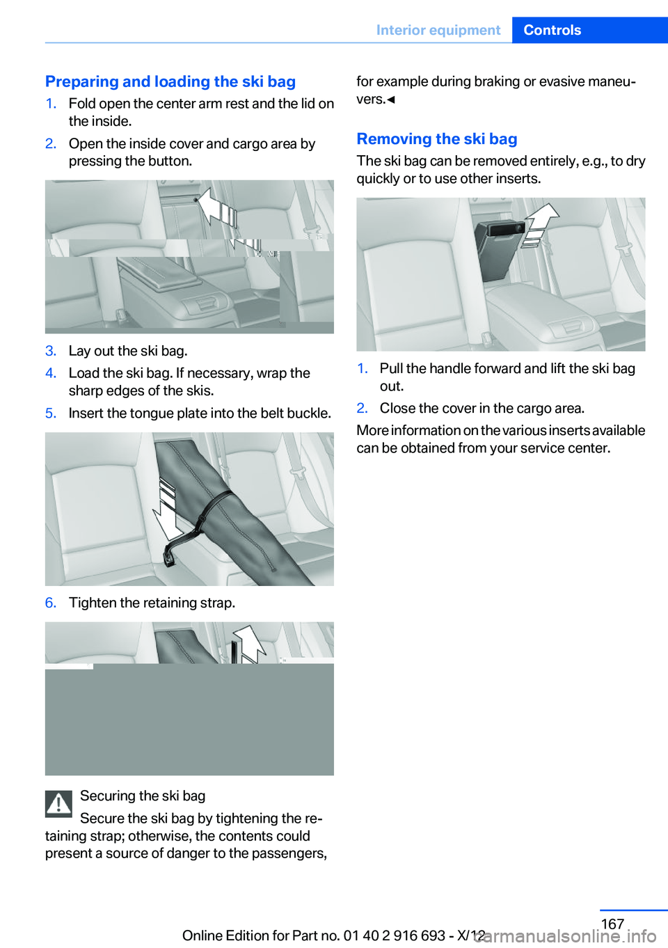
Preparing and loading the ski bag1.Fold open the center arm rest and the lid on
the inside.2.Open the inside cover and cargo area by
pressing the button.3.Lay out the ski bag.4.Load the ski bag. If necessary, wrap the
sharp edges of the skis.5.Insert the tongue plate into the belt buckle.6.Tighten the retaining strap.
Securing the ski bag
Secure the ski bag by tightening the re‐
taining strap; otherwise, the contents could
present a source of danger to the passengers,
for example during braking or evasive maneu‐
vers.◀
Removing the ski bag
The ski bag can be removed entirely, e.g., to dry
quickly or to use other inserts.1.Pull the handle forward and lift the ski bag
out.2.Close the cover in the cargo area.
More information on the various inserts available
can be obtained from your service center.
Seite 167Interior equipmentControls167
Online Edition for Part no. 01 40 2 916 693 - X/12
Page 178 of 243
Stowing cargo▷Cover sharp edges and corners on the
cargo.▷Heavy cargo: stow as far forward as possi‐
ble, directly behind and at the bottom of the
rear passenger seat backrests.▷Very heavy cargo: when the rear seat is not
occupied, secure each of the outer safety
belts in the opposite buckle.
Securing cargo
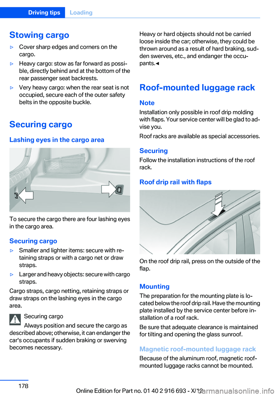
Lashing eyes in the cargo area
To secure the cargo there are four lashing eyes
in the cargo area.
Securing cargo
▷Smaller and lighter items: secure with re‐
taining straps or with a cargo net or draw
straps.▷Larger and heavy objects: secure with cargo
straps.
Cargo straps, cargo netting, retaining straps or
draw straps on the lashing eyes in the cargo
area.
Securing cargo
Always position and secure the cargo as
described above; otherwise, it can endanger the
car's occupants if sudden braking or swerving
becomes necessary.
Heavy or hard objects should not be carried
loose inside the car; otherwise, they could be
thrown around as a result of hard braking, sud‐
den swerves, etc., and endanger the occu‐
pants.◀
Roof-mounted luggage rack
Note
Installation only possible in roof drip molding
with flaps. Your service center will be glad to ad‐
vise you.
Roof racks are available as special accessories.
Securing
Follow the installation instructions of the roof
rack.
Roof drip rail with flaps
On the roof drip rail, press on the outside of the
flap.
Mounting
The preparation for the mounting plate is lo‐
cated below the roof drip rail. Have the mounting
plate installed by the service center before in‐
stallation of a roof rack.
Be sure that adequate clearance is maintained
for tilting and opening the glass sunroof.
Magnetic roof-mounted luggage rack
Because of the aluminum roof, magnetic roof-
mounted luggage racks cannot be mounted.
Seite 178Driving tipsLoading178
Online Edition for Part no. 01 40 2 916 693 - X/12