2013 BMW 650I XDRIVE CONVERTIBLE check engine light
[x] Cancel search: check engine lightPage 45 of 240
▷Make sure that the cargo does not push
against the cargo area partition from below.▷Make sure that the trunk lid is closed.
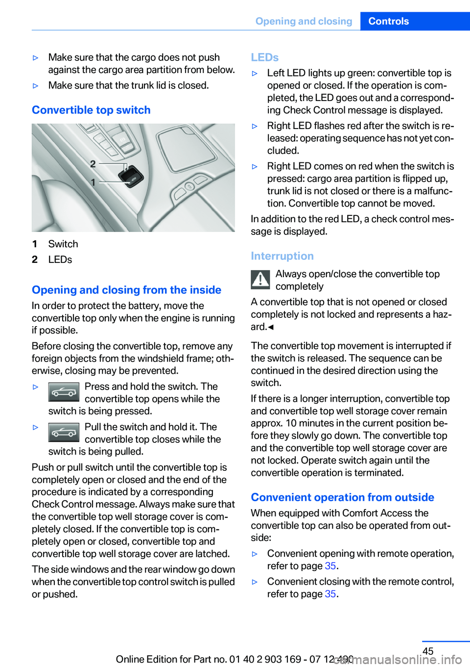
Convertible top switch
1Switch2LEDs
Opening and closing from the inside
In order to protect the battery, move the
convertible top only when the engine is running
if possible.
Before closing the convertible top, remove any
foreign objects from the windshield frame; oth‐
erwise, closing may be prevented.
▷Press and hold the switch. The
convertible top opens while the
switch is being pressed.▷Pull the switch and hold it. The
convertible top closes while the
switch is being pulled.
Push or pull switch until the convertible top is
completely open or closed and the end of the
procedure is indicated by a corresponding
Check Control message. Always make sure that
the convertible top well storage cover is com‐
pletely closed. If the convertible top is com‐
pletely open or closed, convertible top and
convertible top well storage cover are latched.
The side windows and the rear window go down
when the convertible top control switch is pulled
or pushed.
LEDs▷Left LED lights up green: convertible top is
opened or closed. If the operation is com‐
pleted, the LED goes out and a correspond‐
ing Check Control message is displayed.▷Right LED flashes red after the switch is re‐
leased: operating sequence has not yet con‐
cluded.▷Right LED comes on red when the switch is
pressed: cargo area partition is flipped up,
trunk lid is not closed or there is a malfunc‐
tion. Convertible top cannot be moved.
In addition to the red LED, a check control mes‐
sage is displayed.
Interruption Always open/close the convertible top
completely
A convertible top that is not opened or closed
completely is not locked and represents a haz‐
ard.◀
The convertible top movement is interrupted if
the switch is released. The sequence can be
continued in the desired direction using the
switch.
If there is a longer interruption, convertible top
and convertible top well storage cover remain
approx. 10 minutes in the current position be‐
fore they slowly go down. The convertible top
and the convertible top well storage cover are
not locked. Operate switch again until the
convertible operation is terminated.
Convenient operation from outside
When equipped with Comfort Access the
convertible top can also be operated from out‐
side:
▷Convenient opening with remote operation,
refer to page 35.▷Convenient closing with the remote control,
refer to page 35.Seite 45Opening and closingControls45
Online Edition for Part no. 01 40 2 903 169 - 07 12 490
Page 67 of 240

Activating/deactivating the system
manually
Using the button
Press the button.
▷LED comes on: Auto Start Stop function is
deactivated.
The engine is started during an automatic
engine stop.
The engine can only be stopped or started
via the Start/Stop button.▷LED goes out: Auto Start Stop function is
activated.
Switching off the vehicle during an
automatic engine stop
During an automatic engine stop, the vehicle
can be switched off permanently, e.g., when
leaving it.
1.Press the Start/Stop button. The ignition is
switched off. The Auto Start/Stop function
is deactivated.
Automatic transmission: the transmission
position P is engaged automatically.2.Set the parking brake.
Engine start as usual via Start/Stop button.
Automatic deactivation
In certain situations, the Auto Start/Stop func‐
tion is deactivated automatically for safety rea‐
sons, such as when the driver is detected to be
absent.
Malfunction
The Auto Start/Stop function no longer
switches of the engine automatically. A Check
Control message is displayed. It is possible to
continue driving. Have the system checked.
Parking brake
The concept
The parking brake is used to prevent the vehicle
from rolling when it is parked.
Setting
Pull the switch.
The LED lights up.
The indicator lamp lights up red. The
parking brake is set.
Lower lamp: indicator lamp in Canadian
models
Set the parking brake and further secure
the vehicle as required
Set the parking brake firmly when parking; oth‐
erwise, the vehicle could roll. On steep upward
and downward inclines, further secure the vehi‐
cle, for example, by turning the steering wheel in
the direction of the curb. ◀
While driving
Use while driving serves as an emergency brak‐
ing function:
Seite 67DrivingControls67
Online Edition for Part no. 01 40 2 903 169 - 07 12 490
Page 81 of 240
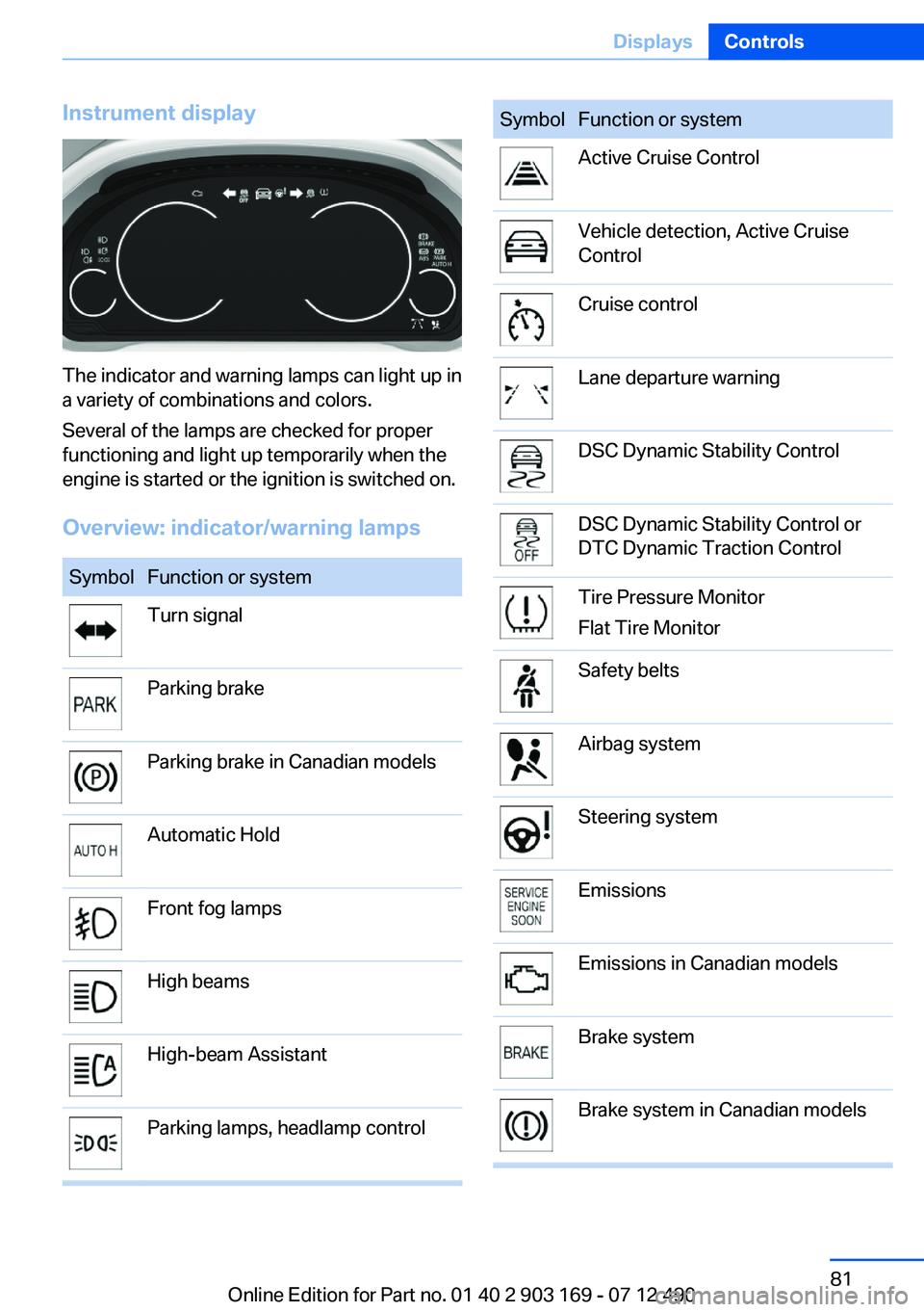
Instrument display
The indicator and warning lamps can light up in
a variety of combinations and colors.
Several of the lamps are checked for proper
functioning and light up temporarily when the
engine is started or the ignition is switched on.
Overview: indicator/warning lamps
SymbolFunction or systemTurn signalParking brakeParking brake in Canadian modelsAutomatic HoldFront fog lampsHigh beamsHigh-beam AssistantParking lamps, headlamp controlSymbolFunction or systemActive Cruise ControlVehicle detection, Active Cruise
ControlCruise controlLane departure warningDSC Dynamic Stability ControlDSC Dynamic Stability Control or
DTC Dynamic Traction ControlTire Pressure Monitor
Flat Tire MonitorSafety beltsAirbag systemSteering systemEmissionsEmissions in Canadian modelsBrake systemBrake system in Canadian modelsSeite 81DisplaysControls81
Online Edition for Part no. 01 40 2 903 169 - 07 12 490
Page 103 of 240
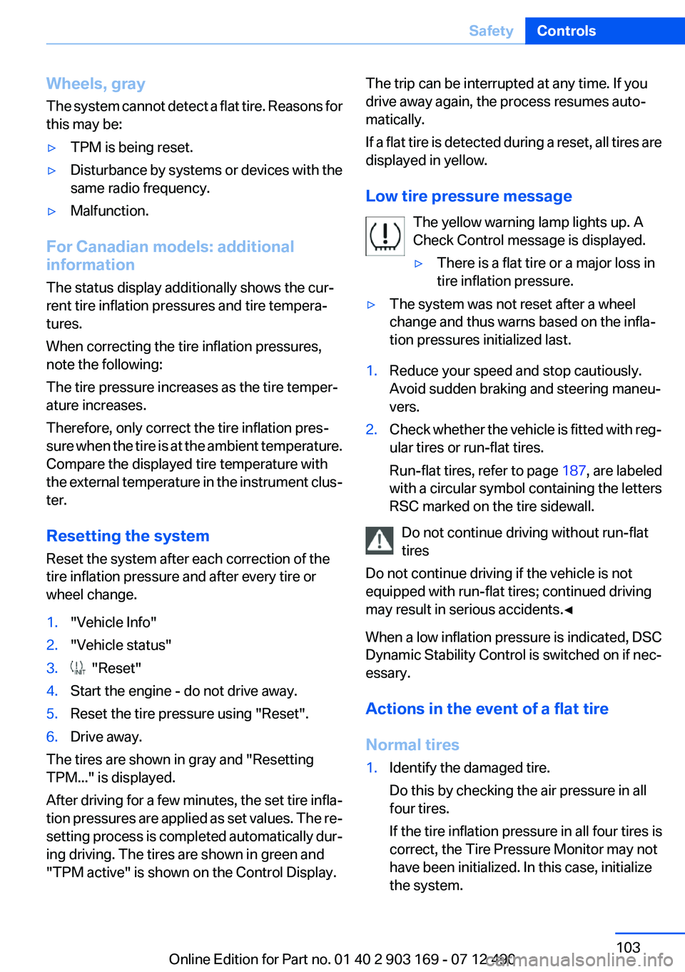
Wheels, gray
The system cannot detect a flat tire. Reasons for
this may be:▷TPM is being reset.▷Disturbance by systems or devices with the
same radio frequency.▷Malfunction.
For Canadian models: additional
information
The status display additionally shows the cur‐
rent tire inflation pressures and tire tempera‐
tures.
When correcting the tire inflation pressures,
note the following:
The tire pressure increases as the tire temper‐
ature increases.
Therefore, only correct the tire inflation pres‐
sure when the tire is at the ambient temperature.
Compare the displayed tire temperature with
the external temperature in the instrument clus‐
ter.
Resetting the system
Reset the system after each correction of the
tire inflation pressure and after every tire or
wheel change.
1."Vehicle Info"2."Vehicle status"3. "Reset"4.Start the engine - do not drive away.5.Reset the tire pressure using "Reset".6.Drive away.
The tires are shown in gray and "Resetting
TPM..." is displayed.
After driving for a few minutes, the set tire infla‐
tion pressures are applied as set values. The re‐
setting process is completed automatically dur‐
ing driving. The tires are shown in green and
"TPM active" is shown on the Control Display.
The trip can be interrupted at any time. If you
drive away again, the process resumes auto‐
matically.
If a flat tire is detected during a reset, all tires are
displayed in yellow.
Low tire pressure message The yellow warning lamp lights up. A
Check Control message is displayed.▷There is a flat tire or a major loss in
tire inflation pressure.▷The system was not reset after a wheel
change and thus warns based on the infla‐
tion pressures initialized last.1.Reduce your speed and stop cautiously.
Avoid sudden braking and steering maneu‐
vers.2.Check whether the vehicle is fitted with reg‐
ular tires or run-flat tires.
Run-flat tires, refer to page 187, are labeled
with a circular symbol containing the letters
RSC marked on the tire sidewall.
Do not continue driving without run-flat
tires
Do not continue driving if the vehicle is not
equipped with run-flat tires; continued driving
may result in serious accidents.◀
When a low inflation pressure is indicated, DSC
Dynamic Stability Control is switched on if nec‐
essary.
Actions in the event of a flat tire
Normal tires
1.Identify the damaged tire.
Do this by checking the air pressure in all
four tires.
If the tire inflation pressure in all four tires is
correct, the Tire Pressure Monitor may not
have been initialized. In this case, initialize
the system.Seite 103SafetyControls103
Online Edition for Part no. 01 40 2 903 169 - 07 12 490
Page 106 of 240
▷When driving on a snowy or slippery road
surface.▷Sporty driving style: slip in the drive wheels,
high lateral acceleration.▷When driving with snow chains.
Status display
The current status of the Flat Tire Monitor can
be displayed on the Control Display, e.g.,
whether or not the FTM is active.
1."Vehicle Info"2."Vehicle status"3. "Flat Tire Monitor"
The status is displayed.
Initialization
The initialization process adopts the set inflation
tire pressures as reference values for the detec‐
tion of a flat tire. Initialization is started by con‐
firming the inflation pressures.
Do not initialize the system when driving with
snow chains.
1."Vehicle Info"2."Vehicle status"3. "Reset"4.Start the engine - do not drive away.5.Start the initialization with "Reset".6.Drive away.
The initialization is completed while driving,
which can be interrupted at any time.
The initialization automatically continues when
driving resumes.
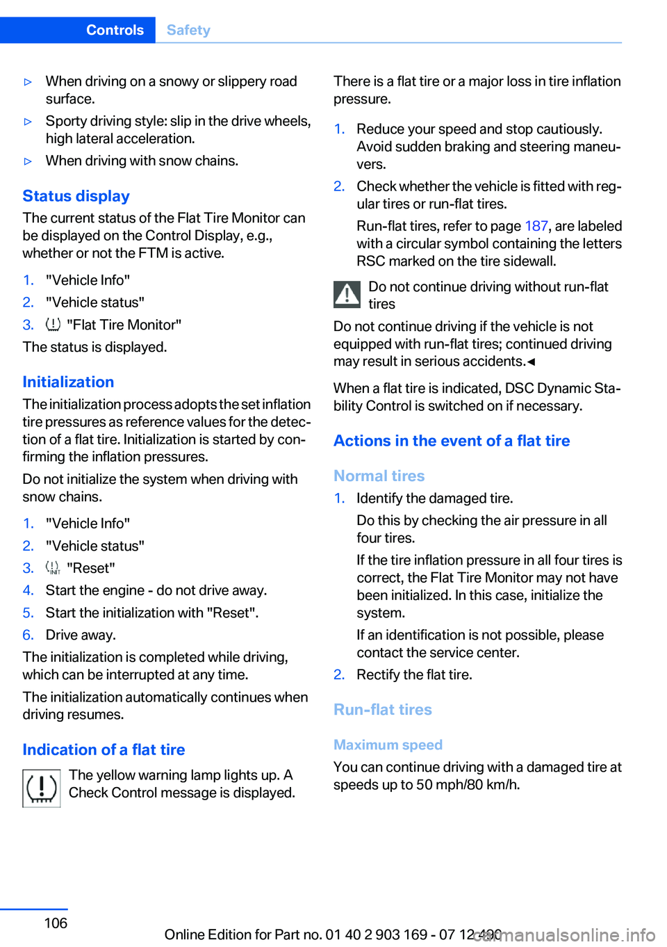
Indication of a flat tire The yellow warning lamp lights up. A
Check Control message is displayed.
There is a flat tire or a major loss in tire inflation
pressure.1.Reduce your speed and stop cautiously.
Avoid sudden braking and steering maneu‐
vers.2.Check whether the vehicle is fitted with reg‐
ular tires or run-flat tires.
Run-flat tires, refer to page 187, are labeled
with a circular symbol containing the letters
RSC marked on the tire sidewall.
Do not continue driving without run-flat
tires
Do not continue driving if the vehicle is not
equipped with run-flat tires; continued driving
may result in serious accidents.◀
When a flat tire is indicated, DSC Dynamic Sta‐
bility Control is switched on if necessary.
Actions in the event of a flat tire
Normal tires
1.Identify the damaged tire.
Do this by checking the air pressure in all
four tires.
If the tire inflation pressure in all four tires is
correct, the Flat Tire Monitor may not have
been initialized. In this case, initialize the
system.
If an identification is not possible, please
contact the service center.2.Rectify the flat tire.
Run-flat tires
Maximum speed
You can continue driving with a damaged tire at
speeds up to 50 mph/80 km/h.
Seite 106ControlsSafety106
Online Edition for Part no. 01 40 2 903 169 - 07 12 490
Page 122 of 240
At speeds up to approx. 37 mph/60 km/h, e.g.,
in curves, the steering angle is increased, i.e.,
steering becomes more direct.
The rear axle steering acts to increase maneu‐
verability by turning the rear wheels slightly in a
direction opposite to the front wheels.
At higher speeds, the steering angle is increas‐
ingly reduced.
The rear wheels are turned to the same angle as
the front wheels.
In critical situations, Integral Active Steering can
specifically steer the front and rear wheels to
stabilize the vehicle before the driver intervenes,
e.g., when braking where road conditions differ
on the left and right sides of the vehicle.
Initializing
In rare cases, it may become necessary to initi‐
alize the Integral Active Steering.
The warning lamp lights up. A Check
Control message is displayed.1.With the engine running, turn the steering
wheel all the way to the left and right several
times in a uniform manner until the warning
lamp disappears.2.Have the system checked if the warning
lamp does not go out after moving the steer‐
ing wheel approx. 6 times or if the steering
wheel is at an angle.
Using snow chains
Ensure that the rear axle steering is deactivated
when using snow chains, refer to page 188.
Programs
The system offers two different programs.
The programs can be selected via the Driving
Experience Switch, refer to page 122.
SPORT
Consistently sporty tuning of the Integral Active
Steering for greater driving agility.
COMFORT
Balanced tuning of the Integral Active Steering
for optimal traveling comfort.
Malfunction
In the event of a malfunction, the steering wheel
must be turned further, while the vehicle re‐
sponds more sensitively to steering wheel
movements in the higher speed range.
The stability-enhancing intervention may be de‐
activated.
Proceed cautiously and drive defensively.
Have the system checked.
Driving Experience Switch
The concept
The Driving Experience Switch can be used to
adjust the driving dynamics of the vehicle. For
this purpose various programs are available for
selection that are activated via the two buttons
of the Driving Experience Switch and the DSC
OFF-button.
Operating the programsPress the buttonProgramDSC OFF
TRACTIONSPORT+
SPORT
COMFORT
COMFORT+
ECO PRO
Automatic program change
The system automatically switches to COM‐
FORT in the following situations:
▷Failure of Integral Active Steering.▷Failure of Dynamic Damping Control.Seite 122ControlsDriving stability control systems122
Online Edition for Part no. 01 40 2 903 169 - 07 12 490
Page 129 of 240
While standingBefore leaving the vehicle, secure it
against rolling.
Before leaving the vehicle with the engine run‐
ning, engage position P of the automatic trans‐
mission and apply the parking brake. Otherwise,
the vehicle may begin to roll.◀
The system brought the vehicle to a complete
standstill.▷Green mark in the speedometer during a
brief idle phase:
The vehicle ahead of you drives away while
the mark is green: your vehicle accelerates
without anything having to be done.▷Switch to orange of the mark in the speed‐
ometer after approx. 2 sec.:
The vehicle ahead of you drives away, while
the mark is orange: in order to accelerate,
briefly press the gas pedal or press the RES
button or SET button.
Rolling bars in the distance indicator mean that
the vehicle ahead of you has driven off.
You actively braked your vehicle to a halt by
pressing on the brake pedal and it is standing
behind another vehicle:
1. Press the button to call up a stored
desired speed.2.Release the brake pedal.3.Press on the accelerator briefly, or press the
RES button or the rocker switch when the
vehicle ahead of you drives away.
Displays in the instrument cluster
Desired speed
▷The marking lights up green:
the system is active.▷The marking lights up or‐
ange: the system has been
interrupted.▷The marking does not light up: the system is
switched off.
With instrument display: the symbol is
displayed in the speedometer similarly
to the mark for the desired speed.
Brief status display Selected desired speed.
If --- appears briefly on the display for Check
Control messages, it is possible that the system
requirements for operation are currently not
met.
Distance to vehicle ahead of you
The selected distance to the vehicle driving
ahead of you is shown.
Distance displayDistance 1Distance 2Distance 3Distance 4
This value is set after the system is
switched on.The system has been interrupted or
distance control is deactivated be‐
cause the accelerator is being
pressed; a vehicle was not detected.Distance control is deactivated be‐
cause the accelerator is being
pressed; a vehicle was detected.Rolling bars: the detected vehicle has driven
away.Seite 129Driving comfortControls129
Online Edition for Part no. 01 40 2 903 169 - 07 12 490
Page 192 of 240
Performing a detailed measurement
In order to perform a detailed measurement of
the engine oil level:1."Vehicle Info"2."Vehicle status"3. "Measure engine oil level"4."Start measurement"
The oil level is checked and displayed via a scale.
Duration: approx. 1 minute.
Adding engine oil
Filler neck
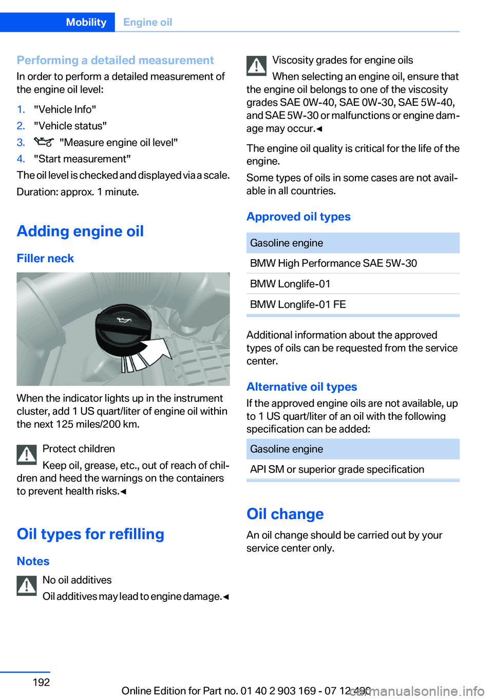
When the indicator lights up in the instrument
cluster, add 1 US quart/liter of engine oil within
the next 125 miles/200 km.
Protect children
Keep oil, grease, etc., out of reach of chil‐
dren and heed the warnings on the containers
to prevent health risks.◀
Oil types for refilling
Notes No oil additives
Oil additives may lead to engine damage. ◀
Viscosity grades for engine oils
When selecting an engine oil, ensure that
the engine oil belongs to one of the viscosity
grades SAE 0W-40, SAE 0W-30, SAE 5W-40,
and SAE 5W-30 or malfunctions or engine dam‐
age may occur.◀
The engine oil quality is critical for the life of the
engine.
Some types of oils in some cases are not avail‐
able in all countries.
Approved oil typesGasoline engineBMW High Performance SAE 5W-30BMW Longlife-01BMW Longlife-01 FE
Additional information about the approved
types of oils can be requested from the service
center.
Alternative oil types
If the approved engine oils are not available, up
to 1 US quart/liter of an oil with the following
specification can be added:
Gasoline engineAPI SM or superior grade specification
Oil change
An oil change should be carried out by your
service center only.
Seite 192MobilityEngine oil192
Online Edition for Part no. 01 40 2 903 169 - 07 12 490