2013 BMW 640I GRAN COUPE clock
[x] Cancel search: clockPage 19 of 305
Example: setting the clock
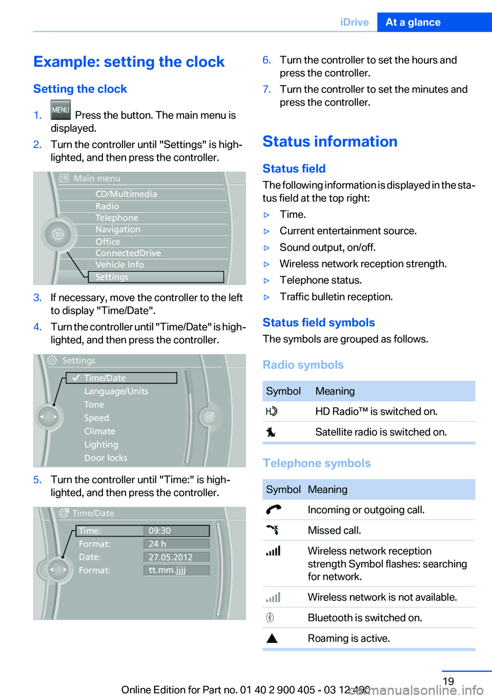
Setting the clock1. Press the button. The main menu is
displayed.2.Turn the controller until "Settings" is high‐
lighted, and then press the controller.3.If necessary, move the controller to the left
to display "Time/Date".4.Turn the controller until "Time/Date" is high‐
lighted, and then press the controller.5.Turn the controller until "Time:" is high‐
lighted, and then press the controller.6.Turn the controller to set the hours and
press the controller.7.Turn the controller to set the minutes and
press the controller.
Status information
Status field
The following information is displayed in the sta‐
tus field at the top right:
▷Time.▷Current entertainment source.▷Sound output, on/off.▷Wireless network reception strength.▷Telephone status.▷Traffic bulletin reception.
Status field symbols
The symbols are grouped as follows.
Radio symbols
SymbolMeaning HD Radio™ is switched on. Satellite radio is switched on.
Telephone symbols
SymbolMeaning Incoming or outgoing call. Missed call. Wireless network reception
strength Symbol flashes: searching
for network. Wireless network is not available. Bluetooth is switched on. Roaming is active.Seite 19iDriveAt a glance19
Online Edition for Part no. 01 40 2 900 405 - 03 12 490
Page 88 of 305

Protective action
Airbags are not triggered in every impact situa‐
tion, e.g., in less severe accidents or rear-end
collisions.
Information on how to ensure the optimal
protective effect of the airbags▷Keep at a distance from the airbags.▷Always grasp the steering wheel on the
steering wheel rim, holding your hands at
the 3 o'clock and 9 o'clock positions, to keep
the danger of injury to your hands or arms as
low as possible if the airbag is triggered.▷There should be no people, animals, or ob‐
jects between an airbag and a person.▷Do not use the cover of the front airbag on
the front passenger side as a storage area.▷Keep the dashboard and window on the
front passenger side clear, i.e., do not cover
with adhesive labels or coverings, and do not
attach holders such as for navigation instru‐
ments and mobile phones.▷Make sure that the front passenger is sitting
correctly, i.e., keeps his or her feet and legs
in the footwell; otherwise, leg injuries can
occur if the front airbag is triggered.▷Do not place slip covers, seat cushions or
other objects on the front passenger seat
that are not approved specifically for seats
with integrated side airbags.▷Do not hang pieces of clothing, such as jack‐
ets, over the backrests.▷Make sure that occupants keep their heads
away from the side airbag and do not rest
against the head airbag; otherwise, injuries
can occur if the airbags are triggered.▷Do not remove the airbag restraint system.▷Do not remove the steering wheel.▷Do not apply adhesive materials to the air‐
bag cover panels, cover them or modify
them in any way.▷Never modify either the individual compo‐
nents or the wiring in the airbag system. This
also applies to steering wheel covers, the
dashboard, the seats, the roof pillars and the
sides of the headliner.◀
Even when all instructions are followed closely,
injury from contact with the airbags cannot be
ruled out in certain situations.
The ignition and inflation noise may lead to
short-term and, in most cases, temporary hear‐
ing impairment in sensitive individuals.
In the case of a malfunction, deactivation
and after triggering of the airbags
Do not touch the individual components imme‐
diately after the system has been triggered; oth‐
erwise, there is the danger of burns.
Only have the airbags checked, repaired or dis‐
mantled and the airbag generator scrapped by
your service center or a workshop that has the
necessary authorization for handling explosives.
Non-professional attempts to service the sys‐
tem could lead to failure in an emergency or un‐
desired triggering of the airbag, either of which
could result in injury.◀
Warnings and information on the airbags are
also found on the sun visors.
Functional readiness of the airbag
system
When the ignition is switch on, the warn‐
ing lamp in the instrument cluster lights
up briefly and thereby indicates the op‐
erational readiness of the entire airbag system
and the belt tensioner.
Airbag system malfunctioning
▷Warning lamp does not come on when the
ignition is turned on.▷The warning lamp lights up continuously.Seite 88ControlsSafety88
Online Edition for Part no. 01 40 2 900 405 - 03 12 490
Page 246 of 305
RefuelingVehicle equipment
All standard, country-specific and optional
equipment that is offered in the model series is
described in this chapter. Therefore, equipment
is also described that is not available in a vehicle,
e. g., because of the selected optional equip‐
ment or country variant. This also applies for
safety-related functions and systems.
General information Refuel promptly
Refuel no later than at a range of
30 miles/50 km, or operation of the engine is not
ensured and damage may occur.◀
Fuel cap
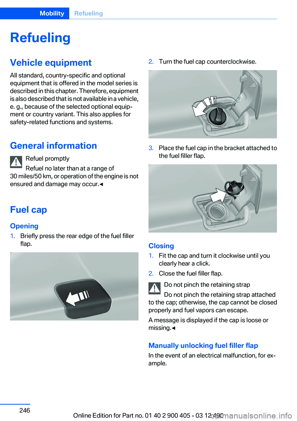
Opening1.Briefly press the rear edge of the fuel filler
flap.2.Turn the fuel cap counterclockwise.3.Place the fuel cap in the bracket attached to
the fuel filler flap.
Closing
1.Fit the cap and turn it clockwise until you
clearly hear a click.2.Close the fuel filler flap.
Do not pinch the retaining strap
Do not pinch the retaining strap attached
to the cap; otherwise, the cap cannot be closed
properly and fuel vapors can escape.
A message is displayed if the cap is loose or
missing.◀
Manually unlocking fuel filler flap
In the event of an electrical malfunction, for ex‐
ample.
Seite 246MobilityRefueling246
Online Edition for Part no. 01 40 2 900 405 - 03 12 490
Page 261 of 305
CoolantVehicle equipment
All standard, country-specific and optional
equipment that is offered in the model series is
described in this chapter. Therefore, equipment
is also described that is not available in a vehicle,
e. g., because of the selected optional equip‐
ment or country variant. This also applies for
safety-related functions and systems.
General information Danger of burns from hot engine
Do not open the cooling system while the
engine is hot; otherwise, escaping coolant may
cause burns.◀
Suitable additives
Only use suitable additives; otherwise, en‐
gine damage may occur. The additives are
harmful to your health.◀
Coolant consists of water and additives.
Not all commercially available additives are suit‐
able for your vehicle. Ask your service center for
suitable additives.Coolant level
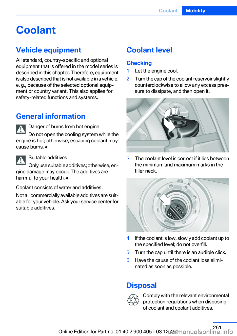
Checking1.Let the engine cool.2.Turn the cap of the coolant reservoir slightly
counterclockwise to allow any excess pres‐
sure to dissipate, and then open it.3.The coolant level is correct if it lies between
the minimum and maximum marks in the
filler neck.4.If the coolant is low, slowly add coolant up to
the specified level; do not overfill.5.Turn the cap until there is an audible click.6.Have the cause of the coolant loss elimi‐
nated as soon as possible.
Disposal
Comply with the relevant environmental
protection regulations when disposing
of coolant and coolant additives.
Seite 261CoolantMobility261
Online Edition for Part no. 01 40 2 900 405 - 03 12 490
Page 267 of 305
Inside brake lamp
Follow the general instructions on lamps and
bulbs, refer to page 264.
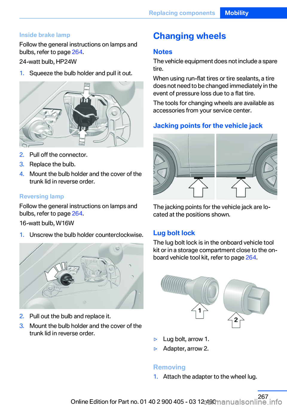
24-watt bulb, HP24W1.Squeeze the bulb holder and pull it out.2.Pull off the connector.3.Replace the bulb.4.Mount the bulb holder and the cover of the
trunk lid in reverse order.
Reversing lamp
Follow the general instructions on lamps and
bulbs, refer to page 264.
16-watt bulb, W16W
1.Unscrew the bulb holder counterclockwise.2.Pull out the bulb and replace it.3.Mount the bulb holder and the cover of the
trunk lid in reverse order.Changing wheels
Notes
The vehicle equipment does not include a spare
tire.
When using run-flat tires or tire sealants, a tire
does not need to be changed immediately in the
event of pressure loss due to a flat tire.
The tools for changing wheels are available as
accessories from your service center.
Jacking points for the vehicle jack
The jacking points for the vehicle jack are lo‐
cated at the positions shown.
Lug bolt lock
The lug bolt lock is in the onboard vehicle tool
kit or in a storage compartment close to the on‐
board vehicle tool kit, refer to page 264.
▷Lug bolt, arrow 1.▷Adapter, arrow 2.
Removing
1.Attach the adapter to the wheel lug.Seite 267Replacing componentsMobility267
Online Edition for Part no. 01 40 2 900 405 - 03 12 490
Page 271 of 305
Assist Response Center contacts you and
takes further steps to help you.
Even if you are unable to respond, the BMW
Assist Response Center can take further
steps to help you under certain circumstan‐
ces.
For this purpose, data that are used to de‐
termine the necessary rescue measures,
such as the current position of the vehicle if
it can be established, are transmitted to the
BMW Assist Response Center.▷If the LED is flashing but the BMW Assist
Response Center cannot be heard on the
hands-free system, the hands-free system
may be malfunctioning. However, the BMW
Assist Response Center may still be able to
hear you.
Initiating an Emergency Request
automatically
Under certain conditions, an Emergency Re‐
quest is automatically initiated immediately after
a severe accident. Automatic Collision Notifica‐
tion is not affected by pressing the SOS button.
Warning triangle
The warning triangle is located on the inside of
the trunk lid.
To remove, loosen the bracket.
First aid kit
The first aid kit is located in a compartment on
the right side in the cargo area. Raise the cover
to remove it.
Some of the articles have a limited service life.
Check the expiration dates of the contents reg‐
ularly and replace any expired items promptly.
Roadside Assistance
Service availability
Roadside Assistance can be reached around the
clock in many countries. You can obtain assis‐
tance there in the event of a vehicle breakdown.
Roadside Assistance
The Roadside Assistance, refer to page 238,
phone number can be viewed on the iDrive or a
connection to Roadside Assistance can be es‐
tablished directly.
Jump-starting
Notes
If the battery is discharged, an engine can be
started using the battery of another vehicle and
two jumper cables. Only use jumper cables with
fully insulated clamp handles.
To prevent personal injury or damage to both
vehicles, adhere strictly to the following proce‐
dure.
Seite 271Breakdown assistanceMobility271
Online Edition for Part no. 01 40 2 900 405 - 03 12 490
Page 295 of 305
Bar for tow-starting/tow‐ing 273
Bass 180
Battery replacement, vehicle battery 268
Battery replacement, vehicle remote control 30
Battery, vehicle 268
Belts, safety belts 49
Beverage holder, cu‐ pholder 145
Blinds, sun protection 43
Bluetooth audio 206
Bluetooth connection, activat‐ ing/deactivating 215
BMW Assist 237
BMW Homepage 6
BMW Internet page 6
BMW Maintenance Sys‐ tem 262
BMW Search 239
Bottle holder, refer to Cu‐ pholder 145
Brake assistant 99
Brake assistant, adaptive 99
Brake discs, breaking in 150
Brake force display 98
Brake lamps, brake force dis‐ play 98
Brake lamps, bulb replace‐ ment 266
Brake lights, adaptive 98
Brake pads, breaking in 150
Braking, notes 151
Breakdown assis‐ tance 270, 271
Breaking in 150
Brightness of Control Dis‐ play 81
Bulb replacement 264
Bulb replacement, front 265
Bulb replacement, rear 266
Bulbs and lamps 264
Button, RES 107
Button, Start/Stop 58 Bypassing, refer to Jump-
starting 271
C
Calendar 231
California Proposition 65 Warning 7
Camera, backup camera 119
Camera, care 278
Camera, Side View 122
Camera, Top View 121
Can holder, refer to Cu‐ pholder 145
Car battery 268
Car care products 276
Care, displays 278
Care, vehicle 276
Cargo 153
Cargo area, enlarging 139
Cargo area lid 38
Cargo area, storage compart‐ ments 145
Cargo straps, securing cargo 154
Car key, refer to Remote con‐ trol 30
Carpet, care 277
Car wash 275
Catalytic converter, refer to Hot exhaust system 150
CBS Condition Based Serv‐ ice 262
CD/DVD 191
CDs, storing 198
Cell phone 214
Center console 14
Center speaker 181
Central locking system 33
Central screen, refer to Control Display 16
Central speaker 181
Changes, technical, refer to Safety 6
Changing parts 264
Changing wheels 267 Changing wheels/tires 253
Check Control 71
Children, seating position 55
Children, transporting safely 55
Child restraint fixing sys‐ tem 55
Child restraint fixing system LATCH 56
Child restraint fixing systems, mounting 55
Child seat, mounting 55
Child seats 55
Chrome parts, care 277
Cigarette lighter 138
Cleaning, displays 278
Climate control 131
Climate control wind‐ shield 151
Clock 74
Closing/opening from in‐ side 37
Closing/opening via door lock 36
Closing/opening with remote control 34
Clothes hooks 145
Collision warning 111
Combination switch, refer to Turn signals 64
Combination switch, refer to Wiper system 64
Comfort Access 39
COMFORT program, Driving Experience Switch 104
Computer 77
Concierge service 238
Condensation on win‐ dows 132
Condensation under the vehi‐ cle 152
Condition Based Service CBS 262
Confirmation signal 35
Contacts 227, 235
Control Display 16 Seite 295Everything from A to ZReference295
Online Edition for Part no. 01 40 2 900 405 - 03 12 490
Page 296 of 305

Control Display, settings 79
Controller 16
Control systems, driving sta‐ bility 99
Convenient opening 35
Coolant 261
Coolant temperature 74
Cooling function 133
Cooling, maximum 132
Cooling system 261
Corrosion on brake discs 152
Cruise control 113
Cruise control, active with Stop & Go 105
Cruising range 75
Cupholder 145
Current fuel consumption 75
Current location, storing 162
Customer Relations 240
D
Damage, tires 253
Damping control, dy‐ namic 101
Data, technical 282
Date 75
Daytime running lights 83
Defrosting, refer to Windows, defrosting 132
Dehumidifying, air 133
Destination distance 78
Destination guidance 168
Destination guidance with in‐ termediate destinations 167
Destination input, naviga‐ tion 160
Digital clock 74
Digital radio 184
Dimensions 282
Dimmable exterior mirrors 53
Dimmable interior rearview mirror 54
Direction indicator, refer to Turn signals 64
Display, ECO PRO 156 Display in windshield 129
Display lighting, refer to Instru‐ ment lighting 85
Displays 70
Displays, cleaning 278
Disposal, coolant 261
Disposal, vehicle battery 268
Distance control, refer to PDC 115
Distance, selecting for ACC 107
Distance to destination 78
Divided screen view, split screen 20
Door lock, refer to Remote control 30
Doors, Automatic Soft Clos‐ ing 38
Drive-off assistant 99
Drive-off assistant, refer to DSC 99
Driving Experience Switch 102
Driving instructions, breaking in 150
Driving notes, general 150
Driving stability control sys‐ tems 99
Driving tips 150
DSC Dynamic Stability Con‐ trol 99
DTC driving dynamics 100
DTC Dynamic Traction Con‐ trol 100
DVD/CD 191
DVD/CD notes 197
DVD changer 195
DVD settings 194
DVDs, storing 198
DVD, video 193
Dynamic Damping Con‐ trol 101
Dynamic destination guid‐ ance 175
Dynamic Drive 101 Dynamic Stability Control
DSC 99
Dynamic Traction Control DTC 100
E
ECO PRO 156
EfficientDynamics 157
EfficientDynamics menu, refer to ECO PRO 156
Electronic displays, instru‐ ment cluster 71
Electronic Stability Program ESP, refer to DSC 99
Emergency detection, remote control 31
Emergency release, door lock 37
Emergency release, fuel filler flap 246
Emergency Request 270
Emergency service, refer to Roadside Assistance 271
Emergency start function, en‐ gine start 31
Emergency unlocking, trunk lid 39
Energy Control 75
Energy recovery 75
Engine, automatic Start/Stop function 59
Engine, automatic switch- off 59
Engine compartment 257
Engine compartment, working in 257
Engine coolant 261
Engine oil 259
Engine oil, adding 259
Engine oil additives 260
Engine oil change 260
Engine oil filler neck 259
Engine oil temperature 74
Engine oil types, alterna‐ tive 260 Seite 296ReferenceEverything from A to Z296
Online Edition for Part no. 01 40 2 900 405 - 03 12 490