2013 BMW 640I GRAN COUPE light
[x] Cancel search: lightPage 127 of 305
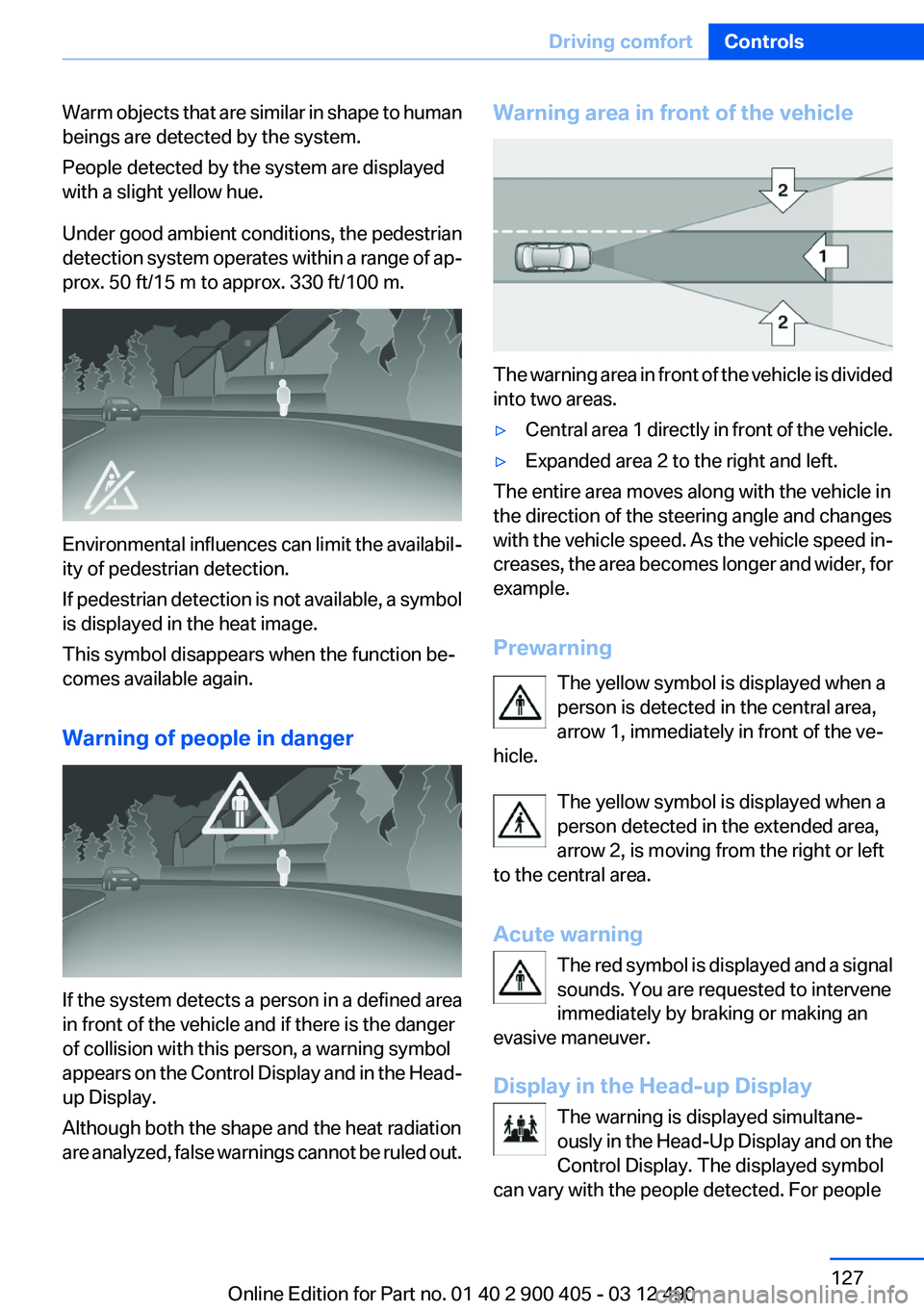
Warm objects that are similar in shape to human
beings are detected by the system.
People detected by the system are displayed
with a slight yellow hue.
Under good ambient conditions, the pedestrian
detection system operates within a range of ap‐
prox. 50 ft/15 m to approx. 330 ft/100 m.
Environmental influences can limit the availabil‐
ity of pedestrian detection.
If pedestrian detection is not available, a symbol
is displayed in the heat image.
This symbol disappears when the function be‐
comes available again.
Warning of people in danger
If the system detects a person in a defined area
in front of the vehicle and if there is the danger
of collision with this person, a warning symbol
appears on the Control Display and in the Head-
up Display.
Although both the shape and the heat radiation
are analyzed, false warnings cannot be ruled out.
Warning area in front of the vehicle
The warning area in front of the vehicle is divided
into two areas.
▷Central area 1 directly in front of the vehicle.▷Expanded area 2 to the right and left.
The entire area moves along with the vehicle in
the direction of the steering angle and changes
with the vehicle speed. As the vehicle speed in‐
creases, the area becomes longer and wider, for
example.
Prewarning The yellow symbol is displayed when a
person is detected in the central area,
arrow 1, immediately in front of the ve‐
hicle.
The yellow symbol is displayed when a
person detected in the extended area,
arrow 2, is moving from the right or left
to the central area.
Acute warning The red symbol is displayed and a signal
sounds. You are requested to intervene
immediately by braking or making an
evasive maneuver.
Display in the Head-up Display The warning is displayed simultane‐
ously in the Head-Up Display and on the
Control Display. The displayed symbol
can vary with the people detected. For people
Seite 127Driving comfortControls127
Online Edition for Part no. 01 40 2 900 405 - 03 12 490
Page 129 of 305
Head-up Display
The concept
This system projects important information into
the driver's field of vision, e.g., the speed.
In this way, the driver can get information with‐
out averting his or her eyes from the road.
Display visibility
The visibility of the displays in the Head-up Dis‐
play is influenced by:
▷Certain sitting positions.▷Objects on the cover of the Head-up Dis‐
play.▷Sunglasses with certain polarization filters.▷Wet roads.▷Unfavorable light conditions.
If the image is distorted, check the basic set‐
tings.
Switching on/off
Press the button.
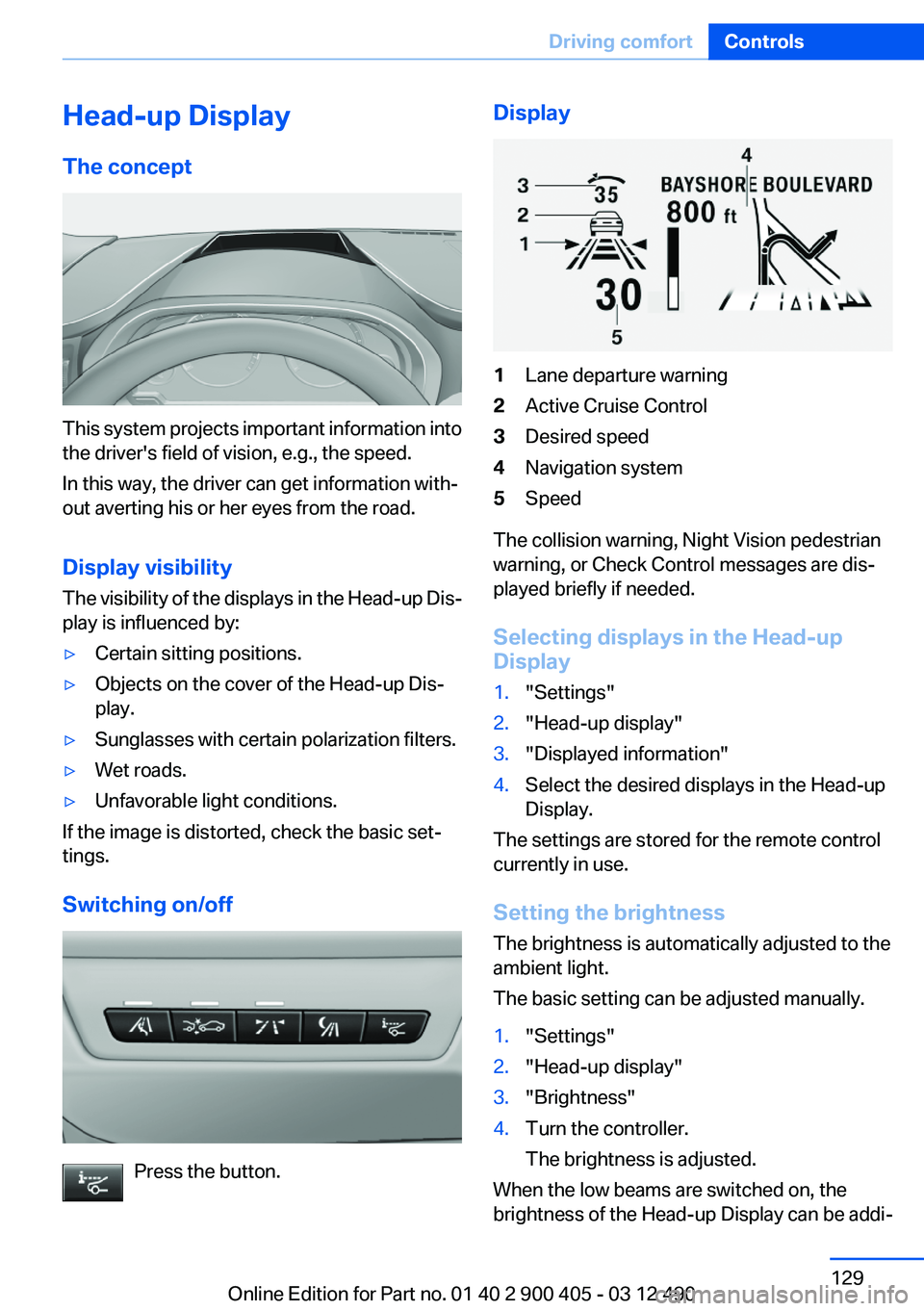
Display1Lane departure warning2Active Cruise Control3Desired speed4Navigation system5Speed
The collision warning, Night Vision pedestrian
warning, or Check Control messages are dis‐
played briefly if needed.
Selecting displays in the Head-up
Display
1."Settings"2."Head-up display"3."Displayed information"4.Select the desired displays in the Head-up
Display.
The settings are stored for the remote control
currently in use.
Setting the brightness
The brightness is automatically adjusted to the
ambient light.
The basic setting can be adjusted manually.
1."Settings"2."Head-up display"3."Brightness"4.Turn the controller.
The brightness is adjusted.
When the low beams are switched on, the
brightness of the Head-up Display can be addi‐
Seite 129Driving comfortControls129
Online Edition for Part no. 01 40 2 900 405 - 03 12 490
Page 130 of 305
tionally influenced using the instrument lighting,
refer to page 85.
The setting is stored for the remote control cur‐
rently in use.
Adjusting the height1."Settings"2."Head-up display"3."Height"4.Turn the controller.
The height is adjusted.
The setting is stored for the remote control cur‐
rently in use.
Special windshield
The windshield is part of the system.
The shape of the windshield makes it possible
to display a precise image.
A film in the windshield prevents double images
from being displayed.
Therefore, have the special windshield replaced
by a service center only.
Seite 130ControlsDriving comfort130
Online Edition for Part no. 01 40 2 900 405 - 03 12 490
Page 135 of 305
Toward red: warmer.▷Lever for changing the air flow direction, ar‐
row 2.▷Thumbwheels for continuous opening and
closing of the vents, arrow 3.
Parked-car ventilation
The concept
The parked-car ventilation ventilates the vehicle
interior and lowers its temperature, if necessary.
The system can be switched on and off directly
or by using two preset switch-on times. It re‐
mains switched on for 30 minutes.
Operation can be performed via iDrive.
Parked-car ventilation
Using the preset switch-on time or when oper‐
ated directly: any external temperature.
Open the vents to allow air to flow out.
Switching on/off directly
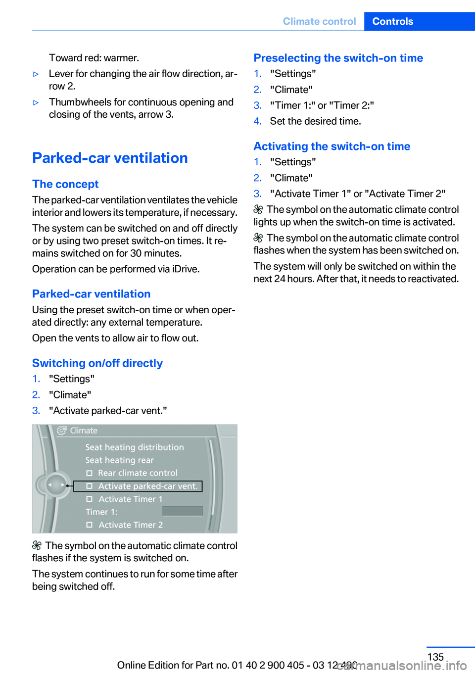
1."Settings"2."Climate"3."Activate parked-car vent."
The symbol on the automatic climate control
flashes if the system is switched on.
The system continues to run for some time after
being switched off.
Preselecting the switch-on time1."Settings"2."Climate"3."Timer 1:" or "Timer 2:"4.Set the desired time.
Activating the switch-on time
1."Settings"2."Climate"3."Activate Timer 1" or "Activate Timer 2"
The symbol on the automatic climate control
lights up when the switch-on time is activated.
The symbol on the automatic climate control
flashes when the system has been switched on.
The system will only be switched on within the
next 24 hours. After that, it needs to reactivated.
Seite 135Climate controlControls135
Online Edition for Part no. 01 40 2 900 405 - 03 12 490
Page 136 of 305
Interior equipmentVehicle equipment
All standard, country-specific and optional
equipment that is offered in the model series is
described in this chapter. Therefore, equipment
is also described that is not available in a vehicle,
e. g., because of the selected optional equip‐
ment or country variant. This also applies for
safety-related functions and systems.
Integrated universal remote
control
The concept
The integrated universal remote control can op‐
erate up to 3 functions of remote-controlled sys‐
tems such as garage door drives or lighting sys‐
tems. The integrated universal remote control
replaces up to 3 different hand-held transmit‐
ters. To operate the remote control, the buttons
on the interior rearview mirror must be program‐
med with the desired functions. The hand-held
transmitter for the particular system is required
in order to program the remote control.
During programming
During programming and before activat‐
ing a device using the integrated universal re‐
mote control, ensure that there are no people,
animals, or objects in the range of movement of
the remote-controlled device; otherwise, there
is a risk of injury or damage.
Also follow the safety instructions of the hand-
held transmitter.◀
Before selling the vehicle, delete the stored
functions for the sake of security.
Compatibility If this symbol is printed on the packaging
or in the instructions of the system to be
controlled, the system is generally com‐patible with the integrated universal remote
control.
If you have any questions, please contact:▷Your service center.▷www.homelink.com on the Internet.
HomeLink is a registered trademark of Johnson
Controls, Inc.
Controls on the interior rearview mirror
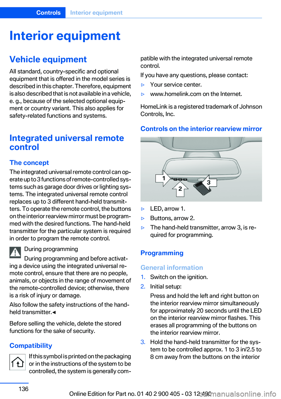
▷LED, arrow 1.▷Buttons, arrow 2.▷The hand-held transmitter, arrow 3, is re‐
quired for programming.
Programming
General information
1.Switch on the ignition.2.Initial setup:
Press and hold the left and right button on
the interior rearview mirror simultaneously
for approximately 20 seconds until the LED
on the interior rearview mirror flashes. This
erases all programming of the buttons on
the interior rearview mirror.3.Hold the hand-held transmitter for the sys‐
tem to be controlled approx. 1 to 3 in/2.5 to
8 cm away from the buttons on the interiorSeite 136ControlsInterior equipment136
Online Edition for Part no. 01 40 2 900 405 - 03 12 490
Page 138 of 305
can then be controlled by the button on the
interior rearview mirror.
If the LED does not flash faster after at least
60 seconds, change the distance and repeat
the step. Several more attempts at different
distances may be necessary. Wait at least
15 seconds between attempts.
Canada: if programming with the hand-held
transmitter was interrupted, hold down the
interior rearview mirror button and repeat‐
edly press and release the hand-held trans‐
mitter button for 2 seconds.
Controls
Before operation
Before operating a system using the
integrated universal remote control, ensure that
there are no people, animals, or objects within
the range of movement of the remote-controlled
system; otherwise, there is a risk of injury or
damage.
Also follow the safety instructions of the hand-
held transmitter.◀
The system, such as the garage door, can be
operated using the button on the interior rear‐
view mirror while the engine is running or when
the ignition is started. To do this, hold down the
button within receiving range of the system until
the function is activated. The interior rearview
mirror LED stays lit while the wireless signal is
being transmitted.
Deleting stored functions
Press and hold the left and right button on the
interior rearview mirror simultaneously for ap‐
proximately 20 seconds until the LED flashes
rapidly. All stored functions are deleted. The
functions cannot be deleted individually.
Ashtray/cigarette lighter
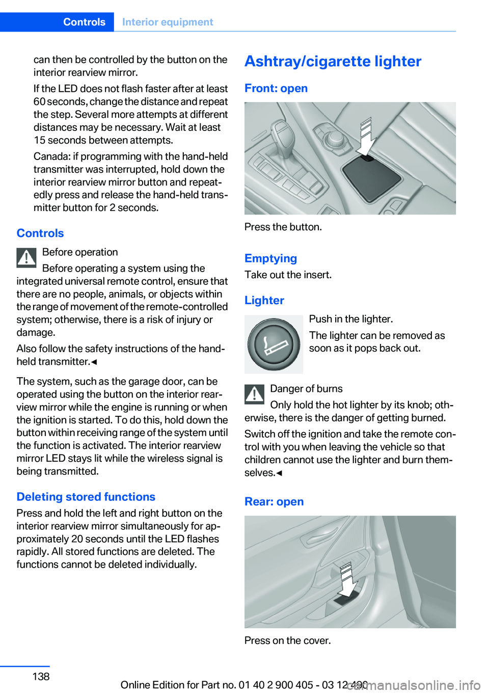
Front: open
Press the button.
Emptying
Take out the insert.
Lighter Push in the lighter.
The lighter can be removed as
soon as it pops back out.
Danger of burns
Only hold the hot lighter by its knob; oth‐
erwise, there is the danger of getting burned.
Switch off the ignition and take the remote con‐
trol with you when leaving the vehicle so that
children cannot use the lighter and burn them‐
selves.◀
Rear: open
Press on the cover.
Seite 138ControlsInterior equipment138
Online Edition for Part no. 01 40 2 900 405 - 03 12 490
Page 139 of 305
Emptying
Take out the insert.
Connecting electrical devices
Note Do not plug the charger into the socket
Do not connect battery chargers to the
factory-installed sockets in the vehicle. Doing so
may result in damage to the vehicle.◀
Sockets
The lighter socket can be used as a socket for
electrical equipment while the engine is running
or when the ignition is switched on. The total
load of all sockets must not exceed 140 watts at
12 volts.
Do not damage the socket by using unsuitable
connectors.
Center console
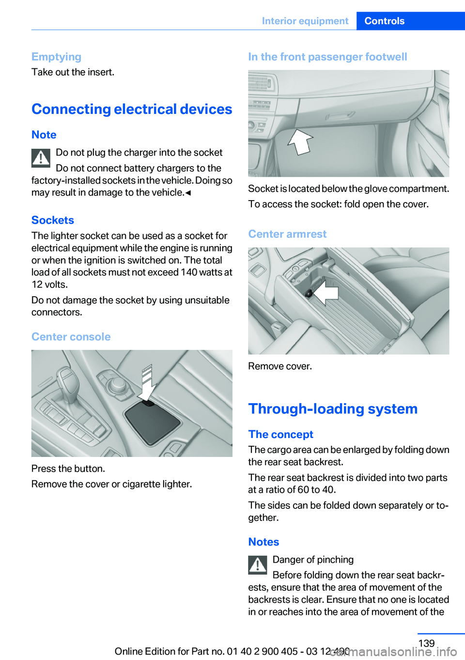
Press the button.
Remove the cover or cigarette lighter.
In the front passenger footwell
Socket is located below the glove compartment.
To access the socket: fold open the cover.
Center armrest
Remove cover.
Through-loading system
The concept
The cargo area can be enlarged by folding down
the rear seat backrest.
The rear seat backrest is divided into two parts
at a ratio of 60 to 40.
The sides can be folded down separately or to‐
gether.
Notes Danger of pinching
Before folding down the rear seat backr‐
ests, ensure that the area of movement of the
backrests is clear. Ensure that no one is located
in or reaches into the area of movement of the
Seite 139Interior equipmentControls139
Online Edition for Part no. 01 40 2 900 405 - 03 12 490
Page 140 of 305
rear seat backrests. Otherwise, injury or damage
may result.◀
Locking the backrest
Before driving with passengers in the rear
of the vehicle, make sure that the backrests are
engaged and thus locked in place. Otherwise,
the restraining effect of the safety belts may be
limited in an accident.◀
Preventing indentations
When folding down the rear seats, ensure
that the safety belt buckles are located in the
recesses provided form them in the seat. Oth‐
erwise they can create indentations in the back‐
rest.◀
Opening1.Unlock the belt lock of the center safety belt
in the rear using the latch plate of another
safety belt.2.Insert the latch plate at the end of the belt
into the specially designated fixture on the
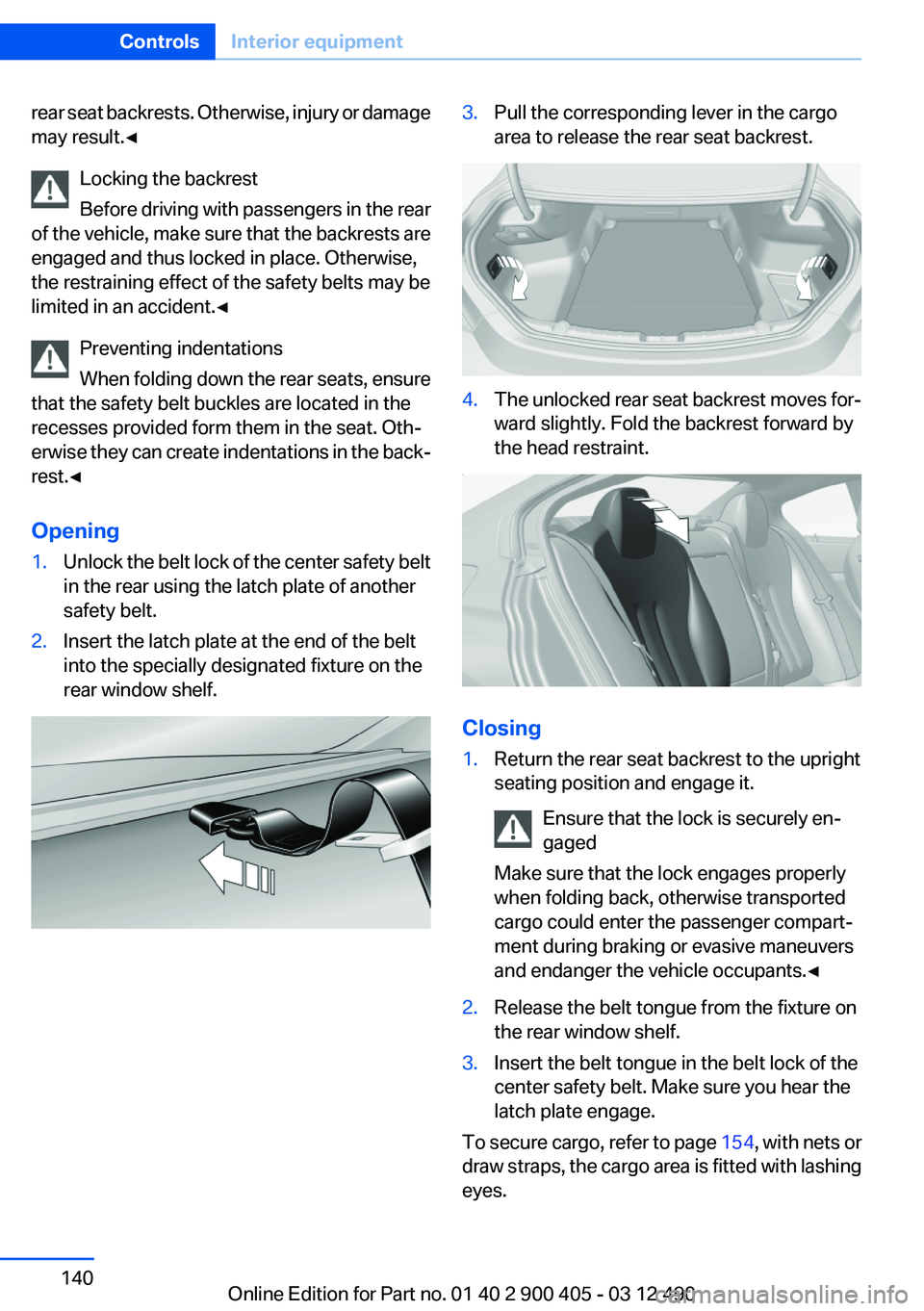
rear window shelf.3.Pull the corresponding lever in the cargo
area to release the rear seat backrest.4.The unlocked rear seat backrest moves for‐
ward slightly. Fold the backrest forward by
the head restraint.
Closing
1.Return the rear seat backrest to the upright
seating position and engage it.
Ensure that the lock is securely en‐
gaged
Make sure that the lock engages properly
when folding back, otherwise transported
cargo could enter the passenger compart‐
ment during braking or evasive maneuvers
and endanger the vehicle occupants.◀2.Release the belt tongue from the fixture on
the rear window shelf.3.Insert the belt tongue in the belt lock of the
center safety belt. Make sure you hear the
latch plate engage.
To secure cargo, refer to page 154, with nets or
draw straps, the cargo area is fitted with lashing
eyes.
Seite 140ControlsInterior equipment140
Online Edition for Part no. 01 40 2 900 405 - 03 12 490