2013 BMW 640I COUPE tow
[x] Cancel search: towPage 90 of 232
Switching the high beams on and off
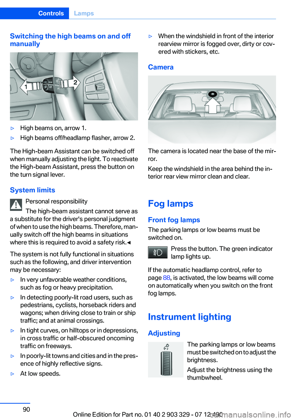
manually▷High beams on, arrow 1.▷High beams off/headlamp flasher, arrow 2.
The High-beam Assistant can be switched off
when manually adjusting the light. To reactivate
the High-beam Assistant, press the button on
the turn signal lever.
System limits Personal responsibility
The high-beam assistant cannot serve as
a substitute for the driver's personal judgment
of when to use the high beams. Therefore, man‐
ually switch off the high beams in situations
where this is required to avoid a safety risk.◀
The system is not fully functional in situations
such as the following, and driver intervention
may be necessary:
▷In very unfavorable weather conditions,
such as fog or heavy precipitation.▷In detecting poorly-lit road users, such as
pedestrians, cyclists, horseback riders and
wagons; when driving close to train or ship
traffic; and at animal crossings.▷In tight curves, on hilltops or in depressions,
in cross traffic or half-obscured oncoming
traffic on freeways.▷In poorly-lit towns and cities and in the pres‐
ence of highly reflective signs.▷At low speeds.▷When the windshield in front of the interior
rearview mirror is fogged over, dirty or cov‐
ered with stickers, etc.
Camera
The camera is located near the base of the mir‐
ror.
Keep the windshield in the area behind the in‐
terior rear view mirror clean and clear.
Fog lamps
Front fog lamps
The parking lamps or low beams must be
switched on.
Press the button. The green indicator
lamp lights up.
If the automatic headlamp control, refer to
page 88, is activated, the low beams will come
on automatically when you switch on the front
fog lamps.
Instrument lighting
Adjusting The parking lamps or low beams
must be switched on to adjust the
brightness.
Adjust the brightness using the
thumbwheel.
Seite 90ControlsLamps90
Online Edition for Part no. 01 40 2 903 329 - 07 12 490
Page 102 of 232
System limitsBe alert
Due to system limitations, warnings may
be not be issued at all, or may be issued late or
improperly. Therefore, always be alert and ready
to intervene; otherwise, there is the danger of an
accident occurring.◀
Detection range
The detection capacity of the camera and the
collision warning has limitations.
This may result in the warning not being issued
or being issued late.
For example, the following situations may not be
detected:▷Slow moving vehicles when you approach
them at high speed.▷Vehicles that suddenly swerve in front of you
or sharply decelerating vehicles.▷Vehicles with an unusual rear appearance.▷Two-wheeled vehicles ahead of you.
Functional limitations
The system may not be fully functional in the
following situations:
▷In heavy fog, rain, sprayed water or snowfall.▷In tight curves.▷If the camera view field or the front wind‐
shield are dirty or covered.▷When driving toward bright lights.▷In the case of vehicles with insufficiently visi‐
ble tail lamps.▷In the case of partially covered vehicles.▷Up to 10 seconds after the start of the en‐
gine, via the Start/Stop knob.▷During the calibration process of the camera
immediately after vehicle shipment.
Prewarning sensitivity
Depending on the set prewarning time, this may
result in increased false warnings.
Camera
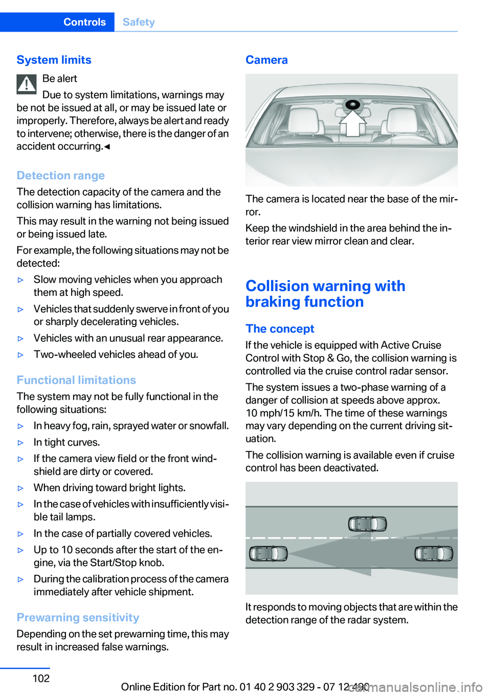
The camera is located near the base of the mir‐
ror.
Keep the windshield in the area behind the in‐
terior rear view mirror clean and clear.
Collision warning with
braking function
The concept
If the vehicle is equipped with Active Cruise
Control with Stop & Go, the collision warning is
controlled via the cruise control radar sensor.
The system issues a two-phase warning of a
danger of collision at speeds above approx.
10 mph/15 km/h. The time of these warnings
may vary depending on the current driving sit‐
uation.
The collision warning is available even if cruise
control has been deactivated.
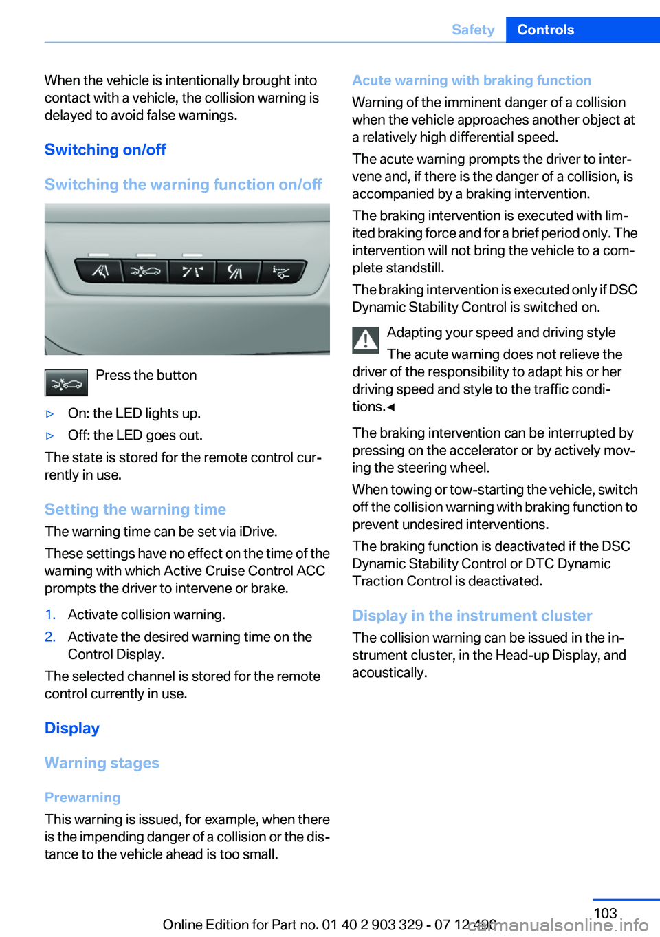
It responds to moving objects that are within the
detection range of the radar system.
Seite 102ControlsSafety102
Online Edition for Part no. 01 40 2 903 329 - 07 12 490
Page 103 of 232
When the vehicle is intentionally brought into
contact with a vehicle, the collision warning is
delayed to avoid false warnings.
Switching on/off
Switching the warning function on/off
Press the button
▷On: the LED lights up.▷Off: the LED goes out.
The state is stored for the remote control cur‐
rently in use.
Setting the warning time
The warning time can be set via iDrive.
These settings have no effect on the time of the
warning with which Active Cruise Control ACC
prompts the driver to intervene or brake.
1.Activate collision warning.2.Activate the desired warning time on the
Control Display.
The selected channel is stored for the remote
control currently in use.
Display
Warning stages
Prewarning
This warning is issued, for example, when there
is the impending danger of a collision or the dis‐
tance to the vehicle ahead is too small.
Acute warning with braking function
Warning of the imminent danger of a collision
when the vehicle approaches another object at
a relatively high differential speed.
The acute warning prompts the driver to inter‐
vene and, if there is the danger of a collision, is
accompanied by a braking intervention.
The braking intervention is executed with lim‐
ited braking force and for a brief period only. The
intervention will not bring the vehicle to a com‐
plete standstill.
The braking intervention is executed only if DSC
Dynamic Stability Control is switched on.
Adapting your speed and driving style
The acute warning does not relieve the
driver of the responsibility to adapt his or her
driving speed and style to the traffic condi‐
tions.◀
The braking intervention can be interrupted by
pressing on the accelerator or by actively mov‐
ing the steering wheel.
When towing or tow-starting the vehicle, switch
off the collision warning with braking function to
prevent undesired interventions.
The braking function is deactivated if the DSC
Dynamic Stability Control or DTC Dynamic
Traction Control is deactivated.
Display in the instrument cluster
The collision warning can be issued in the in‐
strument cluster, in the Head-up Display, and
acoustically.Seite 103SafetyControls103
Online Edition for Part no. 01 40 2 903 329 - 07 12 490
Page 108 of 232
Camera
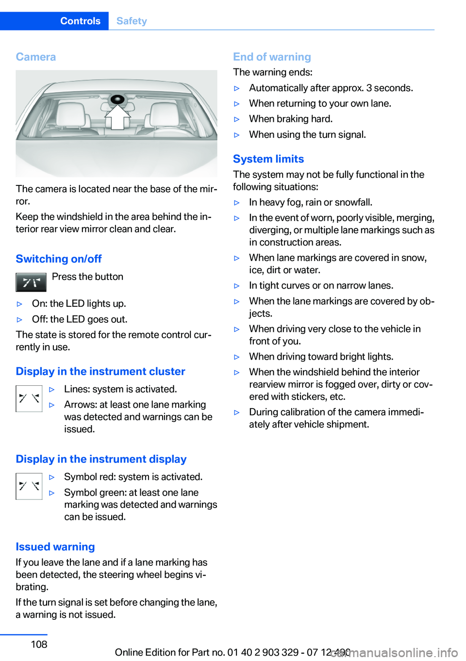
The camera is located near the base of the mir‐
ror.
Keep the windshield in the area behind the in‐
terior rear view mirror clean and clear.
Switching on/off Press the button
▷On: the LED lights up.▷Off: the LED goes out.
The state is stored for the remote control cur‐
rently in use.
Display in the instrument cluster
▷Lines: system is activated.▷Arrows: at least one lane marking
was detected and warnings can be
issued.
Display in the instrument display
▷Symbol red: system is activated.▷Symbol green: at least one lane
marking was detected and warnings
can be issued.
Issued warning
If you leave the lane and if a lane marking has
been detected, the steering wheel begins vi‐
brating.
If the turn signal is set before changing the lane,
a warning is not issued.
End of warning
The warning ends:▷Automatically after approx. 3 seconds.▷When returning to your own lane.▷When braking hard.▷When using the turn signal.
System limits
The system may not be fully functional in the
following situations:
▷In heavy fog, rain or snowfall.▷In the event of worn, poorly visible, merging,
diverging, or multiple lane markings such as
in construction areas.▷When lane markings are covered in snow,
ice, dirt or water.▷In tight curves or on narrow lanes.▷When the lane markings are covered by ob‐
jects.▷When driving very close to the vehicle in
front of you.▷When driving toward bright lights.▷When the windshield behind the interior
rearview mirror is fogged over, dirty or cov‐
ered with stickers, etc.▷During calibration of the camera immedi‐
ately after vehicle shipment.Seite 108ControlsSafety108
Online Edition for Part no. 01 40 2 903 329 - 07 12 490
Page 129 of 232
The range of the sensors is represented in col‐
ors: red, green and yellow.
If the backup camera image was selected last, it
again appears on the display. To switch to PDC:1. "Rear view camera" Select the symbol
on the Control Display.2.Press the controller.
The setting is stored for the remote control cur‐
rently in use.
System limits
Limits of ultrasonic measurement
The detection of objects can reach the physical
limits of ultrasonic measurement, e.g.:
▷With tow bars and trailer hitches.▷With thin or wedge-shaped objects.▷With low objects.▷With objects with corners and sharp edges.
Low objects already displayed, e.g., curbs, can
move into the blind area of the sensors before or
after a continuous tone sounds.
High, protruding objects such as ledges may not
be detected.
False warnings
PDC may issue a warning under the following
conditions even though there is no obstacle
within the detection range:
▷In heavy rain.▷When sensors are very dirty or covered in
ice.▷When sensors are covered in snow.▷On rough road surfaces.▷In large buildings with right angles and
smooth walls, e.g., in underground garages.▷In heavy exhaust.▷Due to other ultrasound sources, e.g.,
sweeping machines, high pressure steam
cleaners or neon lights.Malfunction
A Check Control message is displayed.
The range of the sensors is shown as a shaded
area on the Control Display.
PDC has failed. Have the system checked.
To ensure full operability:▷Keep the sensors clean and free of ice.▷When using high-pressure washers, do not
spray the sensors for long periods and main‐
tain a distance of at least 12 in/30 cm.
Surround View
The concept
Surround View includes the following systems:
▷Backup camera, refer to page 129.▷Side View, refer to page 134.▷Top View, refer to page 132.
It assists the driver when parking, maneuvering
and on blind driveways and intersections.
Backup camera
The concept
The backup camera provides assistance in park‐
ing and maneuvering backwards. The area be‐
hind the vehicle is shown on the Control Display.
Notes Check the traffic situation as well
Check the traffic situation around the ve‐
hicle with your own eyes. Otherwise, an accident
could result from road users or objects located
outside the picture area of the backup camera. ◀
Seite 129Driving comfortControls129
Online Edition for Part no. 01 40 2 903 329 - 07 12 490
Page 138 of 232
3.Adjust the parking position yourself if nec‐
essary.
Interrupting manually
The parking assistant can be interrupted at any
time:
▷ " Parking Assistant" Select the symbol on
the Control Display.▷Press the button.
Interrupting automatically
The system is interrupted automatically in the
following situations:
▷If the driver grasps the steering wheel or if
he takes over steering.▷If a gear is selected that does not match the
instruction on the Control Display.▷If a turn signal is activated in the opposite
direction to the desired side for parking.▷If the vehicle speed exceeds approx.
6 mph/10 km/h.▷On snow-covered or slippery road surfaces
if necessary.▷If doors are open.▷If the Park Distance Control PDC displays
clearances that are too small.▷If a maximum number of parking attempts or
the time taken for parking is exceeded.
A Check Control message is displayed.
Continuing
An interrupted parking procedure can be con‐
tinued if necessary.
Follow the instructions on the Control Display to
do this.
System limits
No parking assistance
The parking assistant does not offer assistance
in the following situations:
▷In tight curves.
Functional limitations
The system may not be fully functional in the
following situations:
▷When sensors are dirty or iced over.▷In heavy fog, rain or snowfall.▷On bumpy road surfaces such as gravel
roads.▷When leaves or snow has collected in the
parking space.
Limits of ultrasonic measurement
The detection of objects can reach the physical
limits of ultrasonic measurement, e.g. in the fol‐
lowing circumstances:
▷With tow bars and trailer hitches.▷With thin or wedge-shaped objects.▷With elevated, protruding objects such as
ledges or cargo.▷With objects with corners and sharp edges.▷With objects with a fine surface structure,
such as fences.
Low objects already displayed, e.g., curbs, can
move into the blind area of the sensors before or
after a continuous tone sounds.
High, protruding objects such as ledges may not
be detected.
The parking assistant may identify parking
spaces that are not suitable for parking.
Malfunction
A Check Control message is displayed.
The parking assistant failed. Have the system
checked.
Seite 138ControlsDriving comfort138
Online Edition for Part no. 01 40 2 903 329 - 07 12 490
Page 144 of 232
is shown on the display of the automatic cli‐
mate control.
The interior temperature, air volume and air dis‐
tribution can be adjusted with the ignition
switched on.
Switching off
At the lowest fan speed, press the left side of the
button on the driver's side.
on the display of the automatic climate control
goes out.
Switching the system on/off
Switching off
▷Complete system: Press and hold the left button on
the driver's side until the control
clicks off.▷On the front passenger side:
Press and hold the left button on
the front passenger side.
Switching on
Press any button except:
▷ALL program.▷Rear window defroster.▷Left side of Air volume button.▷Seat heating.▷Seat ventilation.
Microfilter/activated-charcoal filter
The microfilter removes dust and pollen from
the incoming air.
The activated-charcoal filter removes gaseous
pollutants from the outside air that enters the
vehicle.
This combined filter should be replaced during
scheduled maintenance, refer to page 189, of
your vehicle.
Ventilation
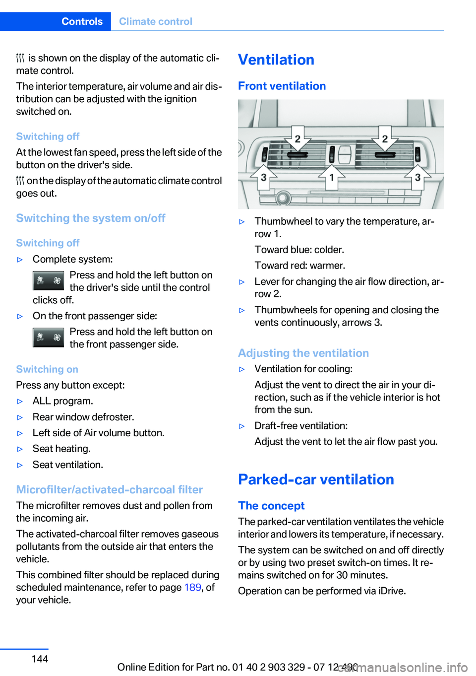
Front ventilation▷Thumbwheel to vary the temperature, ar‐
row 1.
Toward blue: colder.
Toward red: warmer.▷Lever for changing the air flow direction, ar‐
row 2.▷Thumbwheels for opening and closing the
vents continuously, arrows 3.
Adjusting the ventilation
▷Ventilation for cooling:
Adjust the vent to direct the air in your di‐
rection, such as if the vehicle interior is hot
from the sun.▷Draft-free ventilation:
Adjust the vent to let the air flow past you.
Parked-car ventilation
The concept
The parked-car ventilation ventilates the vehicle
interior and lowers its temperature, if necessary.
The system can be switched on and off directly
or by using two preset switch-on times. It re‐
mains switched on for 30 minutes.
Operation can be performed via iDrive.
Seite 144ControlsClimate control144
Online Edition for Part no. 01 40 2 903 329 - 07 12 490
Page 150 of 232
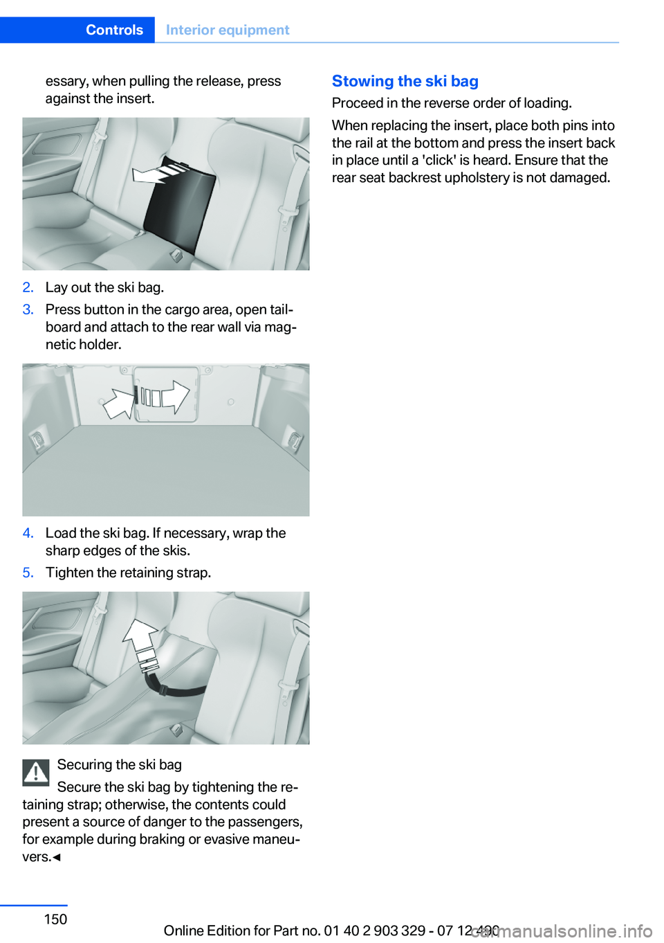
essary, when pulling the release, press
against the insert.2.Lay out the ski bag.3.Press button in the cargo area, open tail‐
board and attach to the rear wall via mag‐
netic holder.4.Load the ski bag. If necessary, wrap the
sharp edges of the skis.5.Tighten the retaining strap.
Securing the ski bag
Secure the ski bag by tightening the re‐
taining strap; otherwise, the contents could
present a source of danger to the passengers,
for example during braking or evasive maneu‐
vers.◀
Stowing the ski bag
Proceed in the reverse order of loading.
When replacing the insert, place both pins into
the rail at the bottom and press the insert back
in place until a 'click' is heard. Ensure that the
rear seat backrest upholstery is not damaged.Seite 150ControlsInterior equipment150
Online Edition for Part no. 01 40 2 903 329 - 07 12 490