Page 105 of 240

▷Disturbance by systems or devices with the
same radio frequency: after leaving the area
of the disturbance, the system automatically
becomes active again.
Declaration according to NHTSA/
FMVSS 138 Tire Pressure Monitoring
System
Each tire, including the spare (if provided)
should be checked monthly when cold and in‐
flated to the inflation pressure recommended by
the vehicle manufacturer on the vehicle placard
or tire inflation pressure label. (If your vehicle has
tires of a different size than the size indicated on
the vehicle placard or tire inflation pressure la‐
bel, you should determine the proper tire infla‐
tion pressure for those tires.) As an added safety
feature, your vehicle has been equipped with a
tire pressure monitoring system (TPMS) that il‐
luminates a low tire pressure telltale when one
or more of your tires is significantly under-in‐
flated. Accordingly, when the low tire pressure
telltale illuminates, you should stop and check
your tires as soon as possible, and inflate them
to the proper pressure. Driving on a significantly
under-inflated tire causes the tire to overheat
and can lead to tire failure. Under-inflation also
reduces fuel efficiency and tire tread life, and
may affect the vehicle's handling and stopping
ability. Please note that the TPMS is not a sub‐
stitute for proper tire maintenance, and it is the
driver's responsibility to maintain correct tire
pressure, even if under-inflation has not reached
the level to trigger illumination of the TPMS low
tire pressure telltale. Your vehicle has also been
equipped with a TPMS malfunction indicator to
indicate when the system is not operating prop‐
erly. The TPMS malfunction indicator is com‐
bined with the low tire pressure telltale. When
the system detects a malfunction, the telltale will
flash for approximately one minute and then re‐
main continuously illuminated. This sequence
will continue upon subsequent vehicle start-ups
as long as the malfunction exists. When the mal‐
function indicator is illuminated, the system may
not be able to detect or signal low tire pressure
as intended. TPMS malfunctions may occur for
a variety of reasons, including the installation of
replacement or alternate tires or wheels on the
vehicle that prevent the TPMS from functioning
properly. Always check the TPMS malfunction
telltale after replacing one or more tires or
wheels on your vehicle to ensure that the re‐
placement or alternate tires and wheels allow
the TPMS to continue to function properly.
FTM Flat Tire Monitor
The concept
The system does not measure the actual infla‐
tion pressure in the tires.
It detects a pressure loss in a tire by comparing
the rotational speeds of the individual wheels
while moving.
In the event of a pressure loss, the diameter and
therefore the rotational speed of the corre‐
sponding wheel change. This is detected and
reported as a flat tire.
Functional requirements
The system must have been initialized when the
tire inflation pressure was correct; otherwise,
reliable signaling of a flat tire is not ensured. In‐
itialize the system after each correction of the
tire inflation pressure and after every tire or
wheel change.
System limits Sudden tire damage
Sudden serious tire damage caused by
external influences cannot be indicated in ad‐
vance.◀
A natural, even pressure loss in all four tires can‐
not be detected. Therefore, check the tire infla‐
tion pressure regularly.
The system could be delayed or malfunction in
the following situations:▷When the system has not been initialized.Seite 105SafetyControls105
Online Edition for Part no. 01 40 2 903 169 - 07 12 490
Page 106 of 240

▷When driving on a snowy or slippery road
surface.▷Sporty driving style: slip in the drive wheels,
high lateral acceleration.▷When driving with snow chains.
Status display
The current status of the Flat Tire Monitor can
be displayed on the Control Display, e.g.,
whether or not the FTM is active.
1."Vehicle Info"2."Vehicle status"3. "Flat Tire Monitor"
The status is displayed.
Initialization
The initialization process adopts the set inflation
tire pressures as reference values for the detec‐
tion of a flat tire. Initialization is started by con‐
firming the inflation pressures.
Do not initialize the system when driving with
snow chains.
1."Vehicle Info"2."Vehicle status"3. "Reset"4.Start the engine - do not drive away.5.Start the initialization with "Reset".6.Drive away.
The initialization is completed while driving,
which can be interrupted at any time.
The initialization automatically continues when
driving resumes.
Indication of a flat tire The yellow warning lamp lights up. A
Check Control message is displayed.
There is a flat tire or a major loss in tire inflation
pressure.1.Reduce your speed and stop cautiously.
Avoid sudden braking and steering maneu‐
vers.2.Check whether the vehicle is fitted with reg‐
ular tires or run-flat tires.
Run-flat tires, refer to page 187, are labeled
with a circular symbol containing the letters
RSC marked on the tire sidewall.
Do not continue driving without run-flat
tires
Do not continue driving if the vehicle is not
equipped with run-flat tires; continued driving
may result in serious accidents.◀
When a flat tire is indicated, DSC Dynamic Sta‐
bility Control is switched on if necessary.
Actions in the event of a flat tire
Normal tires
1.Identify the damaged tire.
Do this by checking the air pressure in all
four tires.
If the tire inflation pressure in all four tires is
correct, the Flat Tire Monitor may not have
been initialized. In this case, initialize the
system.
If an identification is not possible, please
contact the service center.2.Rectify the flat tire.
Run-flat tires
Maximum speed
You can continue driving with a damaged tire at
speeds up to 50 mph/80 km/h.
Seite 106ControlsSafety106
Online Edition for Part no. 01 40 2 903 169 - 07 12 490
Page 107 of 240

Continued driving with a flat tire
If continuing to drive with a damaged tire:1.Avoid sudden braking and steering maneu‐
vers.2.Do not exceed a speed of 50 mph/80 km/h.3.Check the air pressure in all four tires at the
next opportunity.
If the tire inflation pressure in all four tires is
correct, the Flat Tire Monitor may not have
been initialized. In this case, initialize the
system.
Possible driving distance with complete loss of
tire inflation pressure:
The possible driving distance after a loss of tire
inflation pressure depends on the cargo load
and the driving style and conditions.
For a vehicle containing an average load, the
possible driving distance is approx.
50 miles/80 km.
When the vehicle is driven with a damaged tire,
its handling characteristics change, e.g., re‐
duced lane stability during braking, a longer
braking distance, and altered self-steering
properties. Adjust your driving style accord‐
ingly. Avoid abrupt steering maneuvers or driv‐
ing over obstacles, e.g., curbs, potholes, etc.
Because the possible driving distance depends
on how the vehicle is used during the trip, the
actual distance may be smaller or greater de‐
pending on the driving speed, road conditions,
external temperature, cargo load, etc.
Continued driving with a flat tire
Drive moderately and do not exceed a
speed of 50 mph/80 km/h.
A loss of tire inflation pressure results in a
change in the handling characteristics, e.g., re‐
duced lane stability during braking, a longer
braking distance and altered self-steering prop‐
erties.◀
Final tire failure
Vibrations or loud noises while driving can
indicate the final failure of the tire. Reduce speed
and stop; otherwise, pieces of the tire could
come loose and cause an accident. Do not con‐
tinue driving, and contact your service center. ◀
Collision warning
The concept
If the vehicle does not include Active Cruise
Control with Stop & Go, the collision warning is
controlled via the camera in the base of the in‐
terior rearview mirror.
The system issues a two-phase warning of a
danger of collision at speeds above approx.
10 mph/15 km/h. The time of these warnings
may vary depending on the current driving sit‐
uation.
In the process, vehicles in a similar direction of
movement are observed if they are located
within the detection range of the system.
When the vehicle is intentionally brought into
contact with a vehicle, the collision warning is
delayed to avoid misleading warnings.
Warning stages
Prewarning
This warning is issued, for example, when there
is the impending danger of a collision or the dis‐
tance to the vehicle ahead is too small.
Seite 107SafetyControls107
Online Edition for Part no. 01 40 2 903 169 - 07 12 490
Page 108 of 240

Acute warning
Warning of the imminent danger of a collision
when the vehicle approaches another vehicle at
a relatively high differential speed.
Switching the warning function on/off
Press the button
▷On: the LED lights up.▷Off: the LED goes out.
The state is stored for the remote control cur‐
rently in use.
Setting the warning time
The warning time can be set via iDrive.
These settings have no effect on the time of the
warning with which Active Cruise Control ACC
prompts the driver to intervene or brake.
1.Activate collision warning.2.Activate the desired warning time on the
Control Display.
The selected channel is stored for the remote
control currently in use.
Display in the instrument cluster
The collision warning can be issued in the in‐
strument cluster, in the Head-up Display, and
acoustically.
Warning stagesSymbolMeasureThe vehicle lights up red: prewarn‐
ing.
Increase distance.The vehicle flashes red and an
acoustic signal sounds: acute warn‐
ing.
You are requested to intervene by
braking or making an evasive maneu‐
ver.
Adapting your speed and driving style
The display does not relieve the driver of
the responsibility to adapt his or her driving
speed and style to the traffic conditions.◀
System limits Be alert
Due to system limitations, warnings may
be not be issued at all, or may be issued late or
improperly. Therefore, always be alert and ready
to intervene; otherwise, there is the danger of an
accident occurring.◀
Detection range
The detection capacity of the camera and the
collision warning has limitations.
This may result in the warning not being issued
or being issued late.
For example, the following situations may not be
detected:
▷Slow moving vehicles when you approach
them at high speed.▷Vehicles that suddenly swerve in front of you
or sharply decelerating vehicles.▷Vehicles with an unusual rear appearance.▷Two-wheeled vehicles ahead of you.Seite 108ControlsSafety108
Online Edition for Part no. 01 40 2 903 169 - 07 12 490
Page 109 of 240

Functional limitations
The system may not be fully functional in the
following situations:▷In heavy fog, rain, sprayed water or snowfall.▷In tight curves.▷If the camera view field or the front wind‐
shield are dirty or covered.▷When driving toward bright lights.▷In the case of vehicles with insufficiently visi‐
ble tail lamps.▷In the case of partially covered vehicles.▷Up to 10 seconds after the start of the en‐
gine, via the Start/Stop knob.▷During the calibration process of the camera
immediately after vehicle shipment.
Prewarning sensitivity
Depending on the set prewarning time, this may
result in increased false warnings.
Camera
The camera is located near the base of the mir‐
ror.
Keep the windshield in the area behind the in‐
terior rear view mirror clean and clear.
Collision warning with
braking function
The concept
If the vehicle is equipped with Active Cruise
Control with Stop & Go, the collision warning is
controlled via the cruise control radar sensor.
The system issues a two-phase warning of a
danger of collision at speeds above approx.
10 mph/15 km/h. The time of these warnings
may vary depending on the current driving sit‐
uation.
The collision warning is available even if cruise
control has been deactivated.
It responds to moving objects that are within the
detection range of the radar system.
When the vehicle is intentionally brought into
contact with a vehicle, the collision warning is
delayed to avoid false warnings.
Switching on/off
Switching the warning function on/off
Press the button
Seite 109SafetyControls109
Online Edition for Part no. 01 40 2 903 169 - 07 12 490
Page 110 of 240

▷On: the LED lights up.▷Off: the LED goes out.
The state is stored for the remote control cur‐
rently in use.
Setting the warning time
The warning time can be set via iDrive.
These settings have no effect on the time of the
warning with which Active Cruise Control ACC
prompts the driver to intervene or brake.
1.Activate collision warning.2.Activate the desired warning time on the
Control Display.
The selected channel is stored for the remote
control currently in use.
Display
Warning stages
Prewarning
This warning is issued, for example, when there
is the impending danger of a collision or the dis‐
tance to the vehicle ahead is too small.
Acute warning with braking function
Warning of the imminent danger of a collision
when the vehicle approaches another object at
a relatively high differential speed.
The acute warning prompts the driver to inter‐
vene and, if there is the danger of a collision, is
accompanied by a braking intervention.
The braking intervention is executed with lim‐
ited braking force and for a brief period only. The
intervention will not bring the vehicle to a com‐
plete standstill.
The braking intervention is executed only if DSC
Dynamic Stability Control is switched on.
Adapting your speed and driving style
The acute warning does not relieve the
driver of the responsibility to adapt his or her
driving speed and style to the traffic condi‐
tions.◀
The braking intervention can be interrupted by
pressing on the accelerator or by actively mov‐
ing the steering wheel.
When towing or tow-starting the vehicle, switch
off the collision warning with braking function to
prevent undesired interventions.
The braking function is deactivated if the DSC
Dynamic Stability Control or DTC Dynamic
Traction Control is deactivated.
Display in the instrument cluster
The collision warning can be issued in the in‐
strument cluster, in the Head-up Display, and
acoustically.
Warning stagesSymbolMeasureThe vehicle lights up red: prewarn‐
ing.
Increase distance.The vehicle flashes red and an
acoustic signal sounds: acute warn‐
ing.
You are requested to intervene by
braking or making an evasive maneu‐
ver.
Adapting your speed and driving style
The display does not relieve the driver of
the responsibility to adapt his or her driving
speed and style to the traffic conditions.◀
Seite 110ControlsSafety110
Online Edition for Part no. 01 40 2 903 169 - 07 12 490
Page 111 of 240

System limitsBe alert
Due to system limitations, warnings may
be not be issued at all, or may be issued late or
improperly. Therefore, always be alert and ready
to intervene; otherwise, there is the danger of an
accident occurring.◀
Detection range
The detection capacity of the radar sensor and
the collision warning has limitations.
This may result in the warning not being issued
or being issued late.
For example, the following situations may not be
detected:▷Slow moving vehicles when you approach
them at high speed.▷Vehicles that suddenly swerve in front of you
or sharply decelerating vehicles.▷Vehicles with an unusual rear appearance.▷Two-wheeled vehicles ahead of you.▷Pedestrians.
Functional limitations
The system may not be fully functional in the
following situations:
▷In heavy fog, rain, sprayed water or snowfall.▷In tight curves.▷If the radar sensor is dirty or obscured.
Prewarning sensitivity
Depending on the set prewarning time, this may
result in increased false warnings.
Night Vision with pedestrian
detection
The concept
Night Vision with pedestrian detection is a night
vision system.
An infrared camera records the area in front of
the vehicle and displays the image on the Con‐
trol Display.
The picture is a heat image. The system has an
integrated pedestrian detection function that
detects pedestrians and cyclists. Warm objects
that are similar in shape to human beings are
detected by the system.
Personal responsibility
Night Vision cannot replace the driver's
personal judgment of the visibility conditions
and the traffic situation. The view ahead and the
actual visibility conditions must always be the
basis on which the vehicle speed is adjusted;
otherwise, there is a risk to road safety.◀
Heat image
The image shows the heat radiated by objects
in the field of view of the camera.
Warm objects have a light appearance and cold
objects, a dark appearance.
The ability to detect an object depends on the
temperature difference between the object and
the background and on the level of heat radiation
emitted by the object. Objects that are similar in
temperature to the environment or that radiate
very little heat are difficult to detect.
For safety reasons, when driving at speeds
above approx. 3 mph/5 km/h and in low ambient
light, the image is only displayed when the low
beams are switched on.
A still image is displayed at regular intervals for
a fraction of a second.
Seite 111SafetyControls111
Online Edition for Part no. 01 40 2 903 169 - 07 12 490
Page 112 of 240

Pedestrian detection
The pedestrian detection and warning system
only operates in darkness and only when a heat
image is displayed.
Warm objects that are similar in shape to human
beings are detected by the system.
People detected by the system are displayed
with a slight yellow hue.
Under good ambient conditions, the pedestrian
detection system operates within a range of ap‐
prox. 50 ft/15 m to approx. 330 ft/100 m.
Environmental influences can limit the availabil‐
ity of pedestrian detection.
If pedestrian detection is not available, a symbol
is displayed in the heat image.
This symbol disappears when the function be‐
comes available again.
Warning of people in danger
If the system detects a person in a defined area
in front of the vehicle and if there is the danger
of collision with this person, a warning symbol
appears on the Control Display and in the Head-
up Display.
Although both the shape and the heat radiation
are analyzed, false warnings cannot be ruled out.
Warning area in front of the vehicle
The warning area in front of the vehicle is divided
into two areas.
▷Central area 1 directly in front of the vehicle.▷Expanded area 2 to the right and left.
The entire area moves along with the vehicle in
the direction of the steering angle and changes
with the vehicle speed. As the vehicle speed in‐
creases, the area becomes longer and wider, for
example.
Prewarning The yellow symbol is displayed when a
person is detected in the central area,
Seite 112ControlsSafety112
Online Edition for Part no. 01 40 2 903 169 - 07 12 490
 1
1 2
2 3
3 4
4 5
5 6
6 7
7 8
8 9
9 10
10 11
11 12
12 13
13 14
14 15
15 16
16 17
17 18
18 19
19 20
20 21
21 22
22 23
23 24
24 25
25 26
26 27
27 28
28 29
29 30
30 31
31 32
32 33
33 34
34 35
35 36
36 37
37 38
38 39
39 40
40 41
41 42
42 43
43 44
44 45
45 46
46 47
47 48
48 49
49 50
50 51
51 52
52 53
53 54
54 55
55 56
56 57
57 58
58 59
59 60
60 61
61 62
62 63
63 64
64 65
65 66
66 67
67 68
68 69
69 70
70 71
71 72
72 73
73 74
74 75
75 76
76 77
77 78
78 79
79 80
80 81
81 82
82 83
83 84
84 85
85 86
86 87
87 88
88 89
89 90
90 91
91 92
92 93
93 94
94 95
95 96
96 97
97 98
98 99
99 100
100 101
101 102
102 103
103 104
104 105
105 106
106 107
107 108
108 109
109 110
110 111
111 112
112 113
113 114
114 115
115 116
116 117
117 118
118 119
119 120
120 121
121 122
122 123
123 124
124 125
125 126
126 127
127 128
128 129
129 130
130 131
131 132
132 133
133 134
134 135
135 136
136 137
137 138
138 139
139 140
140 141
141 142
142 143
143 144
144 145
145 146
146 147
147 148
148 149
149 150
150 151
151 152
152 153
153 154
154 155
155 156
156 157
157 158
158 159
159 160
160 161
161 162
162 163
163 164
164 165
165 166
166 167
167 168
168 169
169 170
170 171
171 172
172 173
173 174
174 175
175 176
176 177
177 178
178 179
179 180
180 181
181 182
182 183
183 184
184 185
185 186
186 187
187 188
188 189
189 190
190 191
191 192
192 193
193 194
194 195
195 196
196 197
197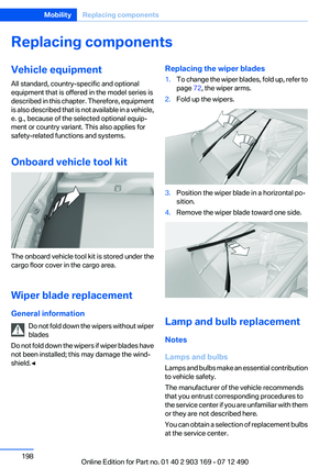 198
198 199
199 200
200 201
201 202
202 203
203 204
204 205
205 206
206 207
207 208
208 209
209 210
210 211
211 212
212 213
213 214
214 215
215 216
216 217
217 218
218 219
219 220
220 221
221 222
222 223
223 224
224 225
225 226
226 227
227 228
228 229
229 230
230 231
231 232
232 233
233 234
234 235
235 236
236 237
237 238
238 239
239