2013 BMW 535I XDRIVE trailer
[x] Cancel search: trailerPage 43 of 246

▷The indicator lamp flashes after locking:
The doors, hood or trunk lid is not closed
properly, but the rest of the vehicle is se‐
cured.
After 10 seconds, the indicator lamp flashes
continuously. Interior motion sensor and tilt
alarm sensor are not active.▷The indicator lamp goes out after unlocking:
The vehicle has not been tampered with.▷The indicator lamp flashes after unlocking
until the engine ignition is switched on, but
no longer than approx. 5 minutes:
An alarm has been triggered.
Tilt alarm sensor
The tilt of the vehicle is monitored.
The alarm system responds in situations such
as attempts to steal a wheel or when the car is
towed.
Interior motion sensor
The windows and glass sunroof must be closed
for the system to function properly.
Avoiding unintentional alarms
The tilt alarm sensor and interior motion sensor
can be switched off together, such as in the fol‐
lowing situations:
▷In automatic car washes.▷In duplex garages.▷During transport on car-carrying trains, at
sea or on a trailer.▷When animals are to remain in the vehicle.
Switching off the tilt alarm sensor and
interior motion sensor
Press the remote control button again
within 10 seconds as soon as the vehicle
is locked.
The indicator lamp lights up for approx. 2 sec‐
onds and then continues to flash.
The tilt alarm sensor and interior motion sensor
are switched off until the vehicle is locked again.
Power windows
General information Take the remote control with you
Take the remote control with you when
leaving the vehicle so that children, for example,
cannot operate the power windows and injure
themselves.◀
Opening
▷ Press the switch to the resistance
point.
The window opens while the switch is held.▷ Press the switch beyond the resist‐
ance point.
The window opens automatically.
Pressing again stops the motion.
Convenient opening, refer to page 34, via the
remote control.
Closing Keep the closing path clear
Monitor the closing process and make
sure that the closing path of the window is clear;
otherwise, injuries may result.◀
▷ Pull the switch to the resistance point.
Seite 43Opening and closingControls43
Online Edition for Part no. 01 40 2 917 522 - II/13
Page 87 of 246

the information stored in the navigation system
and also displays speed limits present on routes
without signs.
No Passing Information
No Passing Information in the instrument cluster
displays the beginnings and ends of no passing
zones detected by the camera. The system ac‐
counts for only the beginnings and ends of No
Passing zones marked by signs.
No display is shown:▷In countries where No Passing zones are
primarily identified with road markings.▷On routes without signage.▷Where there are railroad crossings, highway
markings or other situations where no sig‐
nage is present, but passing would not be
permitted.
Hints
Speed limits when towing a trailer are not
shown.
Personal judgment
The system cannot serve as a substitute
for the driver's personal judgment of the traffic
situation.
The system assists the driver and does not re‐
place the human eye.◀
At a glance
Camera
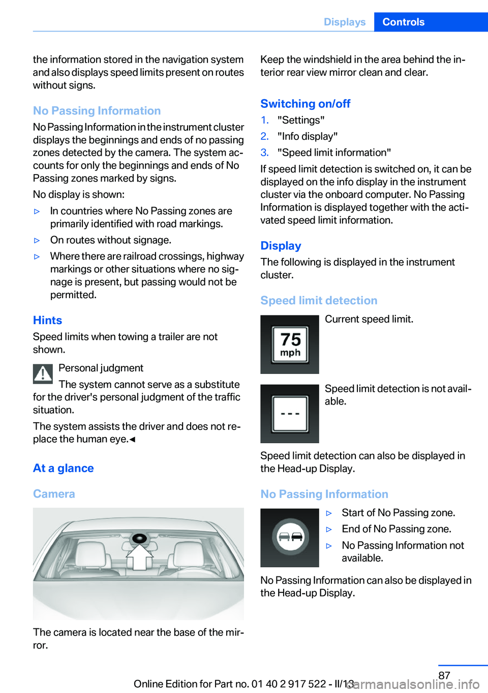
The camera is located near the base of the mir‐
ror.
Keep the windshield in the area behind the in‐
terior rear view mirror clean and clear.
Switching on/off1."Settings"2."Info display"3."Speed limit information"
If speed limit detection is switched on, it can be
displayed on the info display in the instrument
cluster via the onboard computer. No Passing
Information is displayed together with the acti‐
vated speed limit information.
Display
The following is displayed in the instrument
cluster.
Speed limit detection Current speed limit.
Speed limit detection is not avail‐
able.
Speed limit detection can also be displayed in
the Head-up Display.
No Passing Information
▷Start of No Passing zone.▷End of No Passing zone.▷No Passing Information not
available.
No Passing Information can also be displayed in
the Head-up Display.
Seite 87DisplaysControls87
Online Edition for Part no. 01 40 2 917 522 - II/13
Page 96 of 246

Switching off
Briefly press the lever to the resistance point in
the opposite direction.
Adaptive light control
The concept
Adaptive Light Control is a variable headlamp
control system that enables dynamic illumina‐
tion of the road surface.
Depending on the steering angle and other pa‐
rameters, the light from the headlamp follows
the course of the road.
In tight curves, e.g., on mountainous roads or
when turning, an additional, corner-illuminating
lamp is switched on that lights up the inside of
the curve when the vehicle is moving below a
certain speed.
Activating
Switch position
with the ignition switched
on.
The turning lamps are automatically switched
on depending on the steering angle or the use
of turn signals.
To avoid blinding oncoming traffic, the Adaptive
Light Control does not swivel to the driver's side
when the vehicle is at a standstill.
When driving in reverse, only the turning lamp is
active.
Self-leveling headlights
The self-leveling headlights feature adapts the
light distribution to the contours of the road.
The light distribution is lowered on hilltops to
avoid blinding oncoming traffic and tilted in de‐
pressions to increase visibility.
Malfunction
A Check Control message is displayed.
Adaptive light control is malfunctioning or has
failed. Have the system checked as soon as pos‐
sible.
Headlamp range control
With halogen headlamps, the headlamp range of
the low beams can be manually adjusted for the
vehicle load to avoid blinding oncoming traffic.
The values following the slash apply to trailer
operation.
0 / 1 = 1 to 2 people without luggage.
1 / 1 = 5 people without luggage.
1 / 2 = 5 people with luggage.
2 / 2 = 1 person, full cargo area.
High-beam Assistant
The concept
When the low beams are switched on, this sys‐
tem automatically switches the high beams on
and off. The procedure is controlled by a sensor
on the front of the interior rearview mirror. The
assistant ensures that the high beams are
switched on whenever the traffic situation al‐
lows. The driver can intervene at any time and
switch the high beams on and off as usual.
Activating1.Turn the light switch to or .2.Press the button on the turn signal lever, ar‐
row.Seite 96ControlsLamps96
Online Edition for Part no. 01 40 2 917 522 - II/13
Page 119 of 246

Driving stability control systemsVehicle equipment
All standard, country-specific and optional
equipment that is offered in the model series is
described in this chapter. Therefore, equipment
is also described that is not available in a vehicle,
e. g., because of the selected optional equip‐
ment or country variant. This also applies for
safety-related functions and systems.
Antilock Brake System ABS
ABS prevents locking of the wheels during brak‐
ing.
The vehicle remains steerable even during full
brake applications, thus increasing active
safety.
ABS is operational every time you start the en‐
gine.
Brake assistant
When you apply the brakes rapidly, this system
automatically produces the maximum braking
force boost. It thus helps to achieve the shortest
possible braking distance during full braking.
This system utilizes all of the benefits provided
by ABS.
Do not reduce the pressure on the brake pedal
for the duration of the full braking.
Adaptive brake assistant
In combination with the Active Cruise Control,
this system ensures that the brakes respond
even more rapidly when braking in critical situa‐
tions. Refer also to Collision warning, refer to
page 107.Drive-off assistant
This system supports driving away on gradients.
The parking brake is not required.1.Hold the vehicle in place with the foot brake.2.Release the foot brake and drive away with‐
out delay.
After the foot brake is released, the vehicle is
held in place for approx. 2 seconds.
Depending on the vehicle load or when a trailer
is being used, the vehicle may roll back slightly.
Driving off without delay
After releasing the foot brake, start driving
without delay, since the drive-off assistant will
not hold the vehicle in place for more than ap‐
prox. 2 seconds and the vehicle will begin rolling
back.◀
DSC Dynamic Stability
Control
The concept
DSC prevents traction loss in the driving wheels
when driving away and accelerating.
DSC also recognizes unstable vehicle condi‐
tions, such as fishtailing or nose-diving. Subject
to physical limits, DSC helps to keep the vehicle
on a steady course by reducing engine speed
and by applying brakes at individual wheels.
Adjust your driving style to the situation
An appropriate driving style is always the
responsibility of the driver.
The laws of physics cannot be repealed, even
with DSC.
Therefore, do not reduce the additional safety
margin by driving in a risky manner.◀
Seite 119Driving stability control systemsControls119
Online Edition for Part no. 01 40 2 917 522 - II/13
Page 136 of 246

The range of the sensors is represented in col‐
ors: red, green and yellow.
If the backup camera image was selected last, it
again appears on the display. To switch to PDC:1. "Rear view camera" Select the symbol
on the Control Display.2.Press the controller.
The setting is stored for the remote control cur‐
rently in use.
System limits
Limits of ultrasonic measurement
The detection of objects can reach the physical
limits of ultrasonic measurement, e.g.:
▷With tow bars and trailer hitches.▷With thin or wedge-shaped objects.▷With low objects.▷With objects with corners and sharp edges.
Low objects already displayed, e.g., curbs, can
move into the blind area of the sensors before or
after a continuous tone sounds.
High, protruding objects such as ledges may not
be detected.
False warnings
PDC may issue a warning under the following
conditions even though there is no obstacle
within the detection range:
▷In heavy rain.▷When sensors are very dirty or covered in
ice.▷When sensors are covered in snow.▷On rough road surfaces.▷In large buildings with right angles and
smooth walls, e.g., in underground garages.▷In heavy exhaust.▷Due to other ultrasound sources, e.g.,
sweeping machines, high pressure steam
cleaners or neon lights.Malfunction
A Check Control message is displayed.
The range of the sensors is shown as a shaded
area on the Control Display.
PDC has failed. Have the system checked.
To ensure full operability:▷Keep the sensors clean and free of ice.▷When using high-pressure washers, do not
spray the sensors for long periods and main‐
tain a distance of at least 12 in/30 cm.
Surround View
The concept
Surround View comprises various camera as‐
sistance systems that help the driver when park‐
ing, maneuvering, and at complex exits and in‐
tersections.
▷Backup camera, refer to page 136▷Side View, refer to page 141.▷Top View, refer to page 139.
Backup camera
The concept
The backup camera provides assistance in park‐
ing and maneuvering backwards. The area be‐
hind the vehicle is shown on the Control Display.
Notes Check the traffic situation as well
Check the traffic situation around the ve‐
hicle with your own eyes. Otherwise, an accident
could result from road users or objects located
outside the picture area of the backup camera. ◀
Seite 136ControlsDriving comfort136
Online Edition for Part no. 01 40 2 917 522 - II/13
Page 146 of 246

Limits of ultrasonic measurement
The detection of objects can reach the physical
limits of ultrasonic measurement, e.g., in the fol‐
lowing circumstances:▷With tow bars and trailer hitches.▷With thin or wedge-shaped objects.▷With elevated, protruding objects such as
ledges or cargo.▷With objects with corners and sharp edges.▷With objects with a fine surface structure,
such as fences.
Low objects already displayed, e.g., curbs, can
move into the blind area of the sensors before or
after a continuous tone sounds.
High, protruding objects such as ledges may not
be detected.
The parking assistant may identify parking
spaces that are not suitable for parking.
Malfunction
A Check Control message is displayed.
The parking assistant failed. Have the system
checked.
Head-up Display
The concept
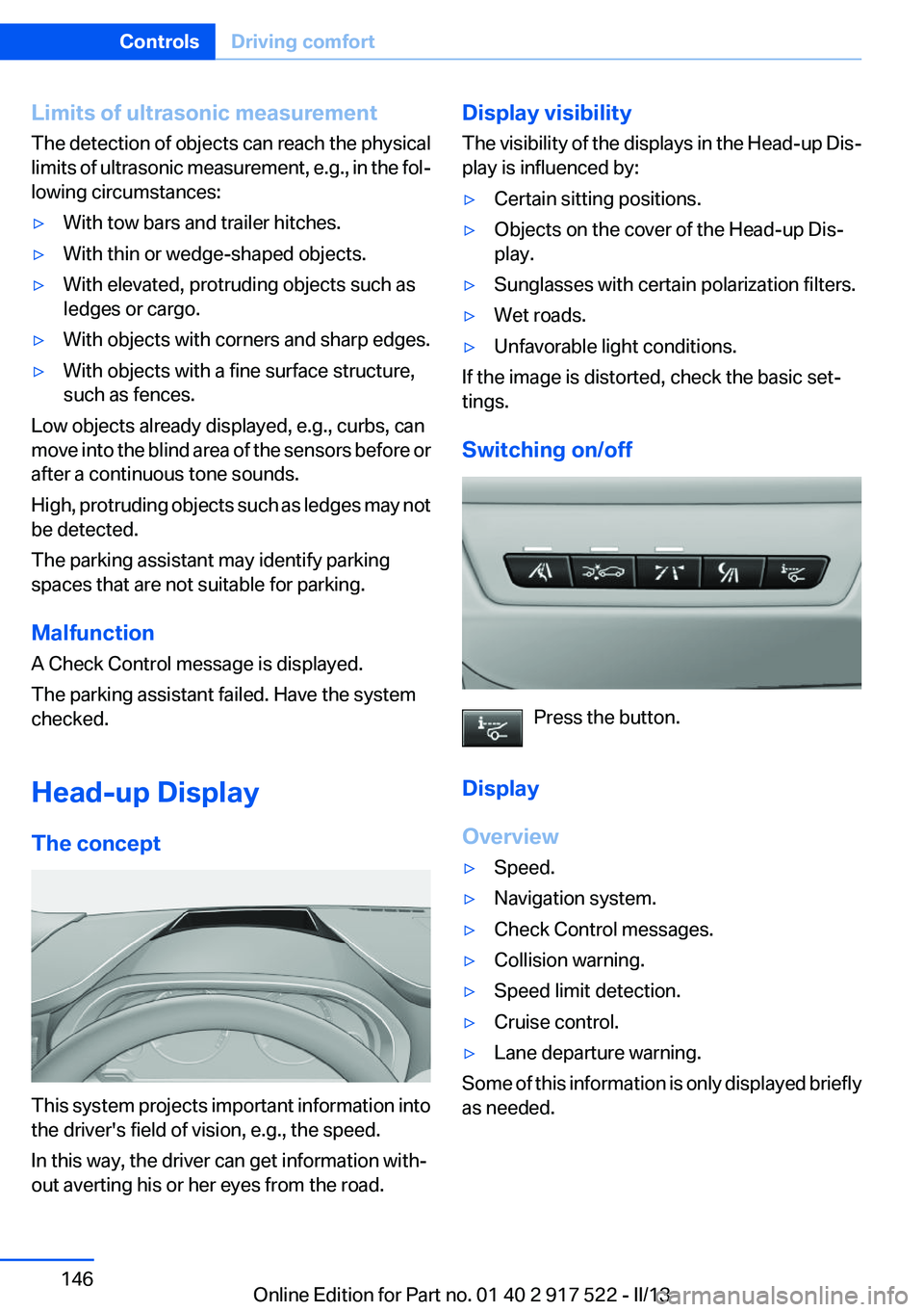
This system projects important information into
the driver's field of vision, e.g., the speed.
In this way, the driver can get information with‐
out averting his or her eyes from the road.
Display visibility
The visibility of the displays in the Head-up Dis‐
play is influenced by:▷Certain sitting positions.▷Objects on the cover of the Head-up Dis‐
play.▷Sunglasses with certain polarization filters.▷Wet roads.▷Unfavorable light conditions.
If the image is distorted, check the basic set‐
tings.
Switching on/off
Press the button.
Display
Overview
▷Speed.▷Navigation system.▷Check Control messages.▷Collision warning.▷Speed limit detection.▷Cruise control.▷Lane departure warning.
Some of this information is only displayed briefly
as needed.
Seite 146ControlsDriving comfort146
Online Edition for Part no. 01 40 2 917 522 - II/13