2013 BMW 535I XDRIVE GRAN TURISMO reset
[x] Cancel search: resetPage 32 of 240
Transmitting the settings
Your personal settings can be taken with you to
another vehicle equipped with the Personal Pro‐
file function. For more information, contact your
service center.
Transmission takes place via:▷The USB interface in the center armrest
onto a USB device.
Profile management
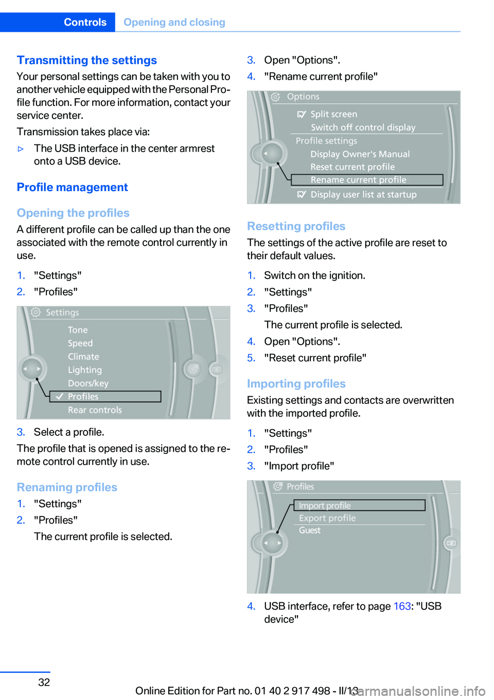
Opening the profiles
A different profile can be called up than the one
associated with the remote control currently in
use.
1."Settings"2."Profiles"3.Select a profile.
The profile that is opened is assigned to the re‐
mote control currently in use.
Renaming profiles
1."Settings"2."Profiles"
The current profile is selected.3.Open "Options".4."Rename current profile"
Resetting profiles
The settings of the active profile are reset to
their default values.
1.Switch on the ignition.2."Settings"3."Profiles"
The current profile is selected.4.Open "Options".5."Reset current profile"
Importing profiles
Existing settings and contacts are overwritten
with the imported profile.
1."Settings"2."Profiles"3."Import profile"4.USB interface, refer to page 163: "USB
device"Seite 32ControlsOpening and closing32
Online Edition for Part no. 01 40 2 917 498 - II/13
Page 55 of 240
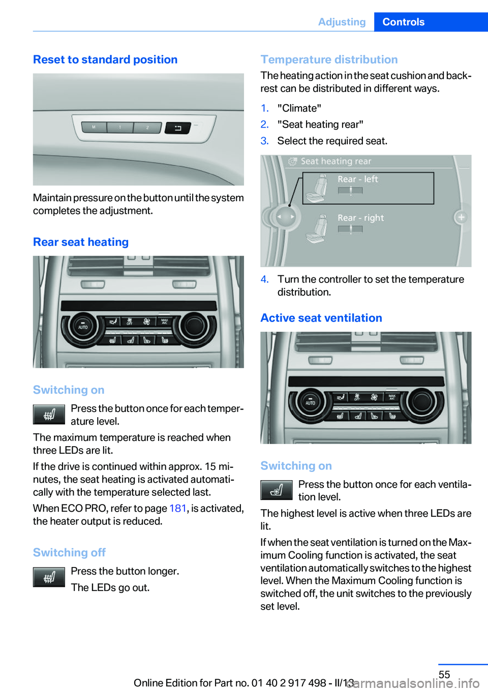
Reset to standard position
Maintain pressure on the button until the system
completes the adjustment.
Rear seat heating
Switching on Press the button once for each temper‐
ature level.
The maximum temperature is reached when
three LEDs are lit.
If the drive is continued within approx. 15 mi‐
nutes, the seat heating is activated automati‐
cally with the temperature selected last.
When ECO PRO, refer to page 181, is activated,
the heater output is reduced.
Switching off Press the button longer.
The LEDs go out.
Temperature distribution
The heating action in the seat cushion and back‐
rest can be distributed in different ways.1."Climate"2."Seat heating rear"3.Select the required seat.4.Turn the controller to set the temperature
distribution.
Active seat ventilation
Switching on
Press the button once for each ventila‐
tion level.
The highest level is active when three LEDs are
lit.
If when the seat ventilation is turned on the Max‐
imum Cooling function is activated, the seat
ventilation automatically switches to the highest
level. When the Maximum Cooling function is
switched off, the unit switches to the previously
set level.
Seite 55AdjustingControls55
Online Edition for Part no. 01 40 2 917 498 - II/13
Page 81 of 240
DisplaysVehicle equipment
All standard, country-specific and optional
equipment that is offered in the model series is
described in this chapter. Therefore, equipmentis also described that is not available in a vehicle,
e. g., because of the selected optional equip‐
ment or country variant. This also applies for
safety-related functions and systems.
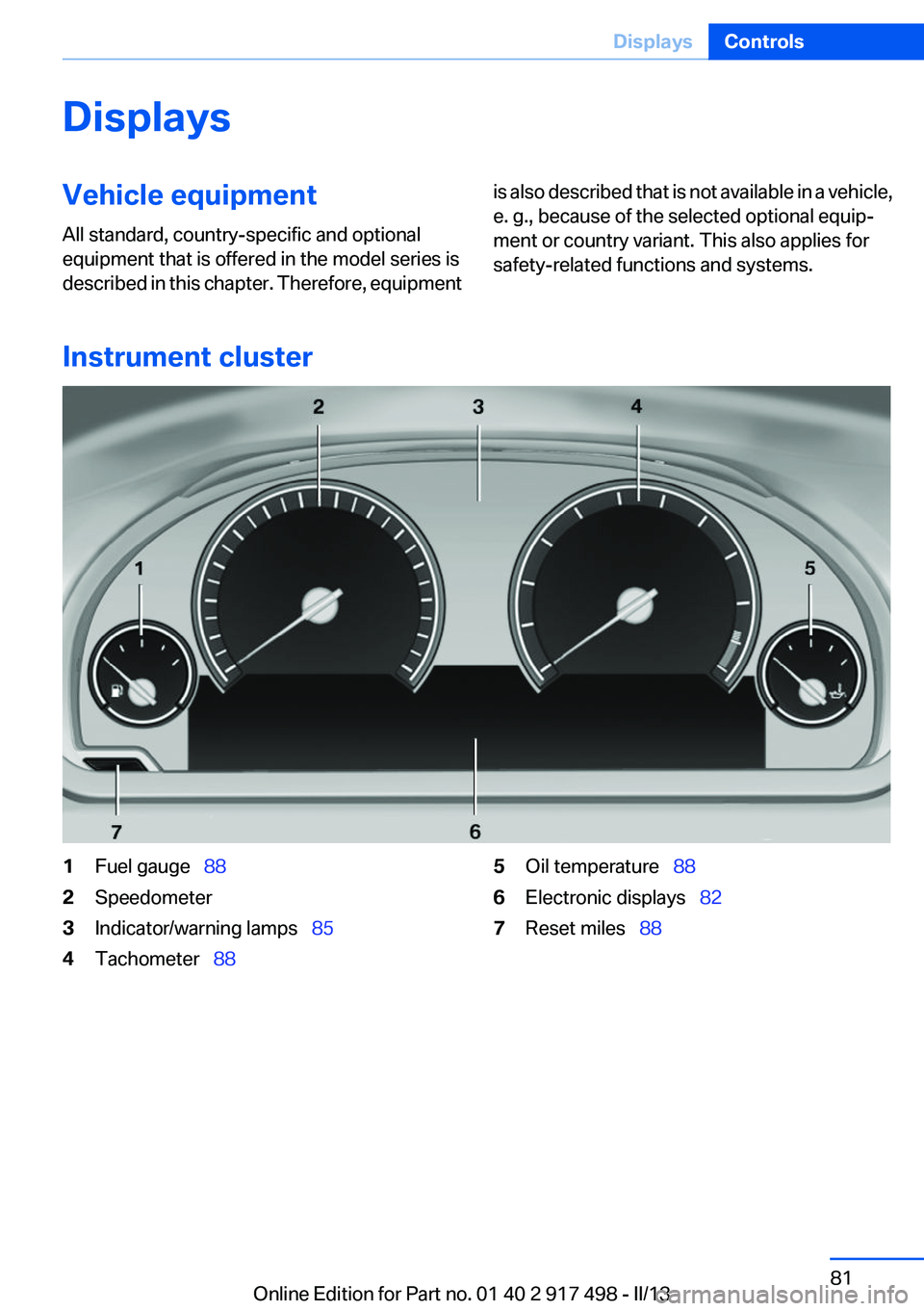
Instrument cluster
1Fuel gauge 882Speedometer3Indicator/warning lamps 854Tachometer 885Oil temperature 886Electronic displays 827Reset miles 88Seite 81DisplaysControls81
Online Edition for Part no. 01 40 2 917 498 - II/13
Page 83 of 240
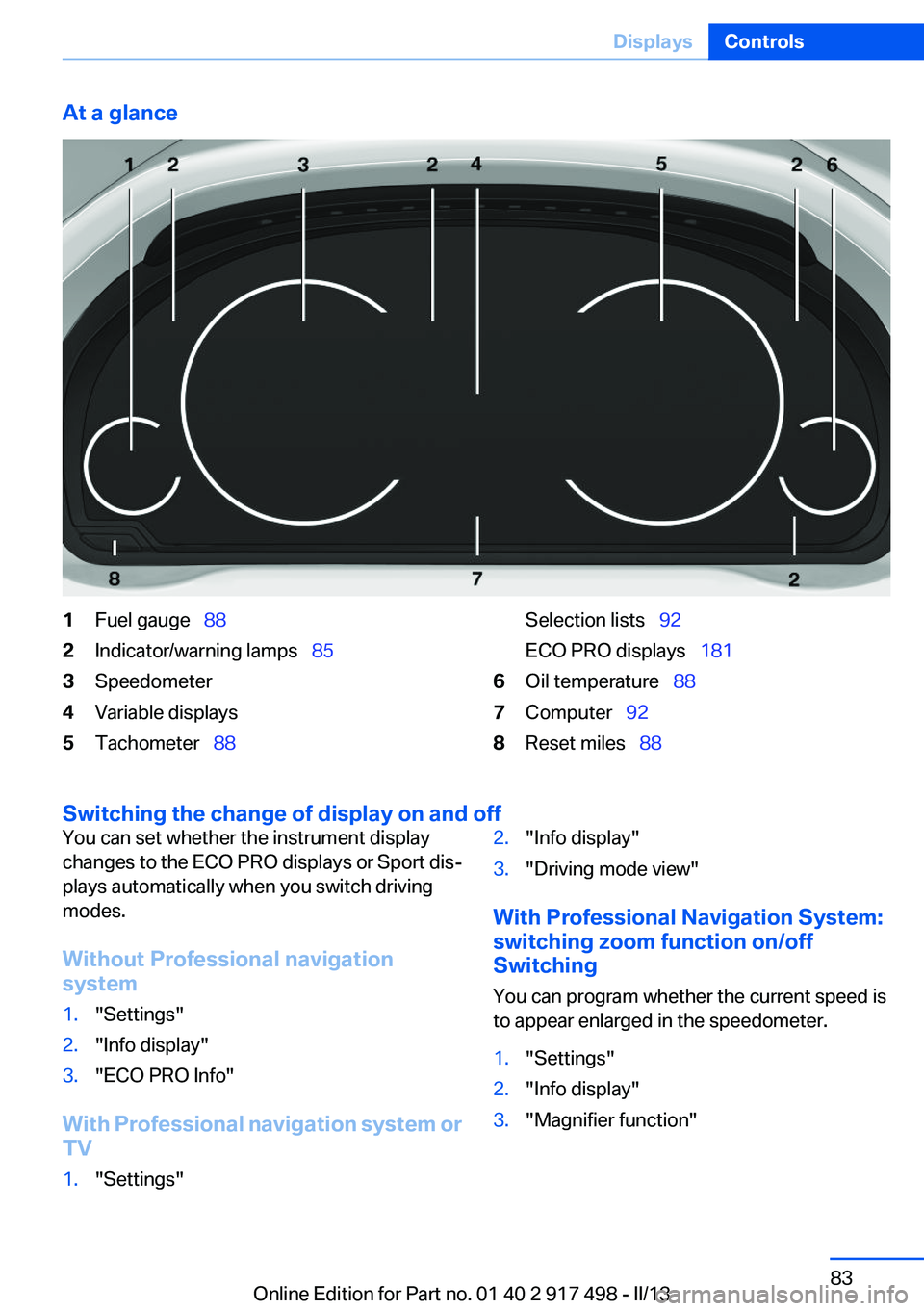
At a glance1Fuel gauge 882Indicator/warning lamps 853Speedometer4Variable displays5Tachometer 88Selection lists 92
ECO PRO displays 1816Oil temperature 887Computer 928Reset miles 88
Switching the change of display on and off
You can set whether the instrument display
changes to the ECO PRO displays or Sport dis‐
plays automatically when you switch driving
modes.
Without Professional navigation
system1."Settings"2."Info display"3."ECO PRO Info"
With Professional navigation system or
TV
1."Settings"2."Info display"3."Driving mode view"
With Professional Navigation System:
switching zoom function on/off
Switching
You can program whether the current speed is
to appear enlarged in the speedometer.
1."Settings"2."Info display"3."Magnifier function"Seite 83DisplaysControls83
Online Edition for Part no. 01 40 2 917 498 - II/13
Page 88 of 240
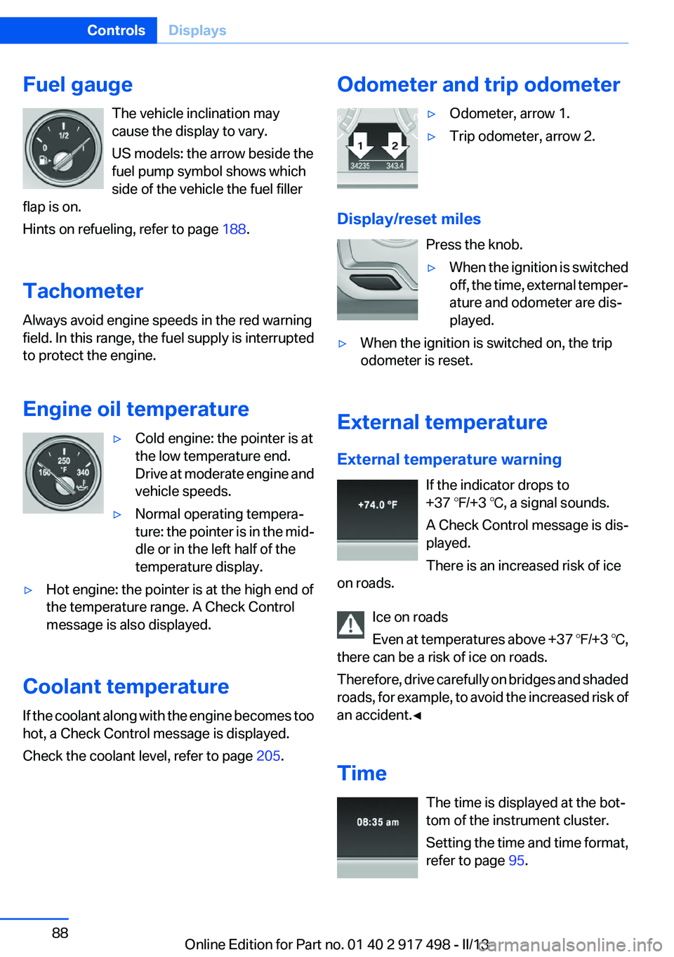
Fuel gaugeThe vehicle inclination may
cause the display to vary.
US models: the arrow beside the
fuel pump symbol shows which
side of the vehicle the fuel filler
flap is on.
Hints on refueling, refer to page 188.
Tachometer
Always avoid engine speeds in the red warning
field. In this range, the fuel supply is interrupted
to protect the engine.
Engine oil temperature▷Cold engine: the pointer is at
the low temperature end.
Drive at moderate engine and
vehicle speeds.▷Normal operating tempera‐
ture: the pointer is in the mid‐
dle or in the left half of the
temperature display.▷Hot engine: the pointer is at the high end of
the temperature range. A Check Control
message is also displayed.
Coolant temperature
If the coolant along with the engine becomes too
hot, a Check Control message is displayed.
Check the coolant level, refer to page 205.
Odometer and trip odometer▷Odometer, arrow 1.▷Trip odometer, arrow 2.
Display/reset miles
Press the knob.
▷When the ignition is switched
off, the time, external temper‐
ature and odometer are dis‐
played.▷When the ignition is switched on, the trip
odometer is reset.
External temperature
External temperature warning If the indicator drops to
+37 ℉/+3 ℃, a signal sounds.
A Check Control message is dis‐
played.
There is an increased risk of ice
on roads.
Ice on roads
Even at temperatures above +37 ℉/+3 ℃,
there can be a risk of ice on roads.
Therefore, drive carefully on bridges and shaded
roads, for example, to avoid the increased risk of
an accident.◀
Time The time is displayed at the bot‐
tom of the instrument cluster.
Setting the time and time format,
refer to page 95.
Seite 88ControlsDisplays88
Online Edition for Part no. 01 40 2 917 498 - II/13
Page 93 of 240
Information at a glance
Repeatedly pressing the button on the turn sig‐
nal lever calls up the following information on the
info display:▷Range.▷Average fuel consumption.▷Average speed.▷Date.▷Speed limit detection.▷Time of arrival.
When destination guidance is activated in
the navigation system.▷Distance to destination.
When destination guidance is activated in
the navigation system.▷Arrow view of navigation system.
When destination guidance is activated in
the navigation system.
When the arrow view in the Head-up Display
is inactive.▷ECO PRO bonus range.
Adjusting the info display
You can select what information from the on‐
board computer is to be displayed on the info
display of the instrument cluster.
1."Settings"2."Info display"3.Select the desired displays.
Information in detail
Range
Displays the estimated cruising range available
with the remaining fuel.
It is calculated based on your driving style over
the last 20 miles/30 km. If there is only enough
fuel left for less than 45 miles/80 km, the color
of the display changes.
Average fuel consumption
This is calculated for the period during which the
engine is running.
The average fuel consumption is calculated for
the distance traveled since the last reset by the
onboard computer.
Average speed
Periods in which the vehicle is parked with the
engine manually stopped do not enter into the
calculation of the average speed.
Resetting average values
Press and hold the computer button on the turn
signal lever.
Distance to destination
The distance remaining to the destination is dis‐
played if a destination is entered in the naviga‐
tion system before the trip is started.
The distance to the destination is adopted au‐
tomatically.
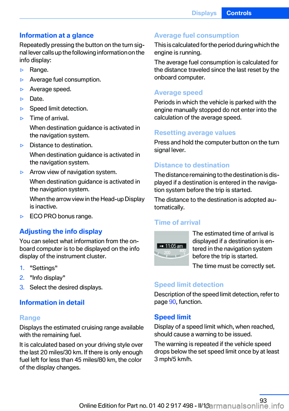
Time of arrival The estimated time of arrival is
displayed if a destination is en‐
tered in the navigation system
before the trip is started.
The time must be correctly set.
Speed limit detection
Description of the speed limit detection, refer to
page 90, function.
Speed limit
Display of a speed limit which, when reached,
should cause a warning to be issued.
The warning is repeated if the vehicle speed
drops below the set speed limit once by at least
3 mph/5 km/h.Seite 93DisplaysControls93
Online Edition for Part no. 01 40 2 917 498 - II/13
Page 94 of 240
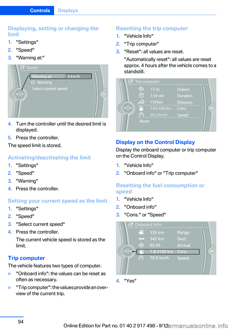
Displaying, setting or changing the
limit1."Settings"2."Speed"3."Warning at:"4.Turn the controller until the desired limit is
displayed.5.Press the controller.
The speed limit is stored.
Activating/deactivating the limit
1."Settings"2."Speed"3."Warning"4.Press the controller.
Setting your current speed as the limit
1."Settings"2."Speed"3."Select current speed"4.Press the controller.
The current vehicle speed is stored as the
limit.
Trip computer
The vehicle features two types of computer.
▷"Onboard info": the values can be reset as
often as necessary.▷" Trip computer": the values provide an over‐
view of the current trip.Resetting the trip computer1."Vehicle Info"2."Trip computer"3."Reset": all values are reset.
"Automatically reset": all values are reset
approx. 4 hours after the vehicle comes to a
standstill.
Display on the Control Display
Display the onboard computer or trip computer
on the Control Display.
1."Vehicle Info"2."Onboard info" or "Trip computer"
Resetting the fuel consumption or
speed
1."Vehicle Info"2."Onboard info"3."Cons." or "Speed"4."Yes"Seite 94ControlsDisplays94
Online Edition for Part no. 01 40 2 917 498 - II/13
Page 105 of 240
sure that the indicator lamp for the front pas‐
senger airbags lights up. This indicates that the
child seat has been detected and the front pas‐
senger airbags are not activated.
Strength of the driver's and front
passenger airbag
The strength with which the driver's and front
passenger airbags are triggered depends on the
position of the driver's and front passenger
seats.
To maintain the accuracy of this function over
the long-term, calibrate the front seats when a
corresponding message appears on the Control
Display.
Calibrating the front seats
A corresponding message appears on the Con‐
trol Display.1.Move the respective seat forward all the
way.2.Move the respective seat forward again. It
moves forward briefly.3.Readjust the seat to the desired position.
The calibration procedure is completed when
the message on the Control Display disappears.
If the message continues to be displayed, repeat
the calibration.
If the message does not disappear after a repeat
calibration, have the system checked as soon as
possible.
Unobstructed area of movement
Ensure that the area of movement of the
seats is unobstructed to avoid personal injury or
damage to objects.◀
FTM Flat Tire Monitor
The concept
The system does not measure the actual infla‐
tion pressure in the tires.
It detects a pressure loss in a tire by comparing
the rotational speeds of the individual wheels
while moving.
In the event of a pressure loss, the diameter and
therefore the rotational speed of the corre‐
sponding wheel change. This is detected and
reported as a flat tire.
Functional requirements
The system must have been initialized when the
tire inflation pressure was correct; otherwise,
reliable signaling of a flat tire is not ensured. In‐
itialize the system after each correction of the
tire inflation pressure and after every tire or
wheel change.
Status display
The current status of the Flat Tire Monitor can
be displayed on the Control Display, e.g.,
whether or not the FTM is active.1."Vehicle Info"2."Vehicle status"3. "Flat Tire Monitor"
The status is displayed.
Initialization
The initialization process adopts the set inflation
tire pressures as reference values for the detec‐
tion of a flat tire. Initialization is started by con‐
firming the inflation pressures.
Do not initialize the system when driving with
snow chains.
1."Vehicle Info"2."Vehicle status"3. "Reset"4.Start the engine - do not drive away.5.Start the initialization with "Reset".6.Drive away.
The initialization is completed while driving,
which can be interrupted at any time.
Seite 105SafetyControls105
Online Edition for Part no. 01 40 2 917 498 - II/13