2013 BMW 535I XDRIVE GRAN TURISMO rear view mirror
[x] Cancel search: rear view mirrorPage 117 of 240
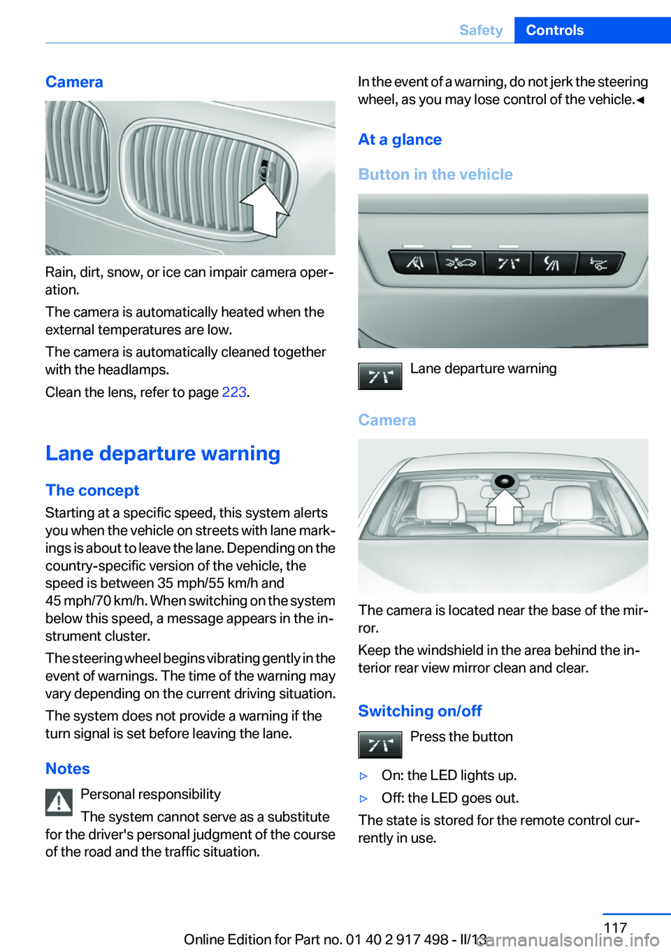
Camera
Rain, dirt, snow, or ice can impair camera oper‐
ation.
The camera is automatically heated when the
external temperatures are low.
The camera is automatically cleaned together
with the headlamps.
Clean the lens, refer to page 223.
Lane departure warning
The concept
Starting at a specific speed, this system alerts
you when the vehicle on streets with lane mark‐
ings is about to leave the lane. Depending on the
country-specific version of the vehicle, the
speed is between 35 mph/55 km/h and
45 mph/70 km/h. When switching on the system
below this speed, a message appears in the in‐
strument cluster.
The steering wheel begins vibrating gently in the
event of warnings. The time of the warning may
vary depending on the current driving situation.
The system does not provide a warning if the
turn signal is set before leaving the lane.
Notes Personal responsibility
The system cannot serve as a substitute
for the driver's personal judgment of the course
of the road and the traffic situation.
In the event of a warning, do not jerk the steering
wheel, as you may lose control of the vehicle.◀
At a glance
Button in the vehicle
Lane departure warning
Camera
The camera is located near the base of the mir‐
ror.
Keep the windshield in the area behind the in‐
terior rear view mirror clean and clear.
Switching on/off Press the button
▷On: the LED lights up.▷Off: the LED goes out.
The state is stored for the remote control cur‐
rently in use.
Seite 117SafetyControls117
Online Edition for Part no. 01 40 2 917 498 - II/13
Page 118 of 240
Display in the instrument cluster▷Lines: system is activated.▷Arrows: at least one lane marking
was detected and warnings can be
issued.
Display in the instrument display
▷Symbol red: system is activated.▷Symbol green: at least one lane
marking was detected and warnings
can be issued.
Issued warning
If you leave the lane and if a lane marking has
been detected, the steering wheel begins vi‐
brating.
If the turn signal is set before changing the lane,
a warning is not issued.
End of warning
The warning ends:
▷Automatically after approx. 3 seconds.▷When returning to your own lane.▷When braking hard.▷When using the turn signal.
System limits
The system may not be fully functional in the
following situations:
▷In heavy fog, rain or snowfall.▷In the event of worn, poorly visible, merging,
diverging, or multiple lane markings such as
in construction areas.▷When lane markings are covered in snow,
ice, dirt or water.▷In tight curves or on narrow lanes.▷When the lane markings are covered by ob‐
jects.▷When driving very close to the vehicle in
front of you.▷When driving toward bright lights.▷When the windshield behind the interior
rearview mirror is fogged over, dirty or cov‐
ered with stickers, etc.▷During calibration of the camera immedi‐
ately after vehicle shipment.
Active Blind Spot Detection
The concept
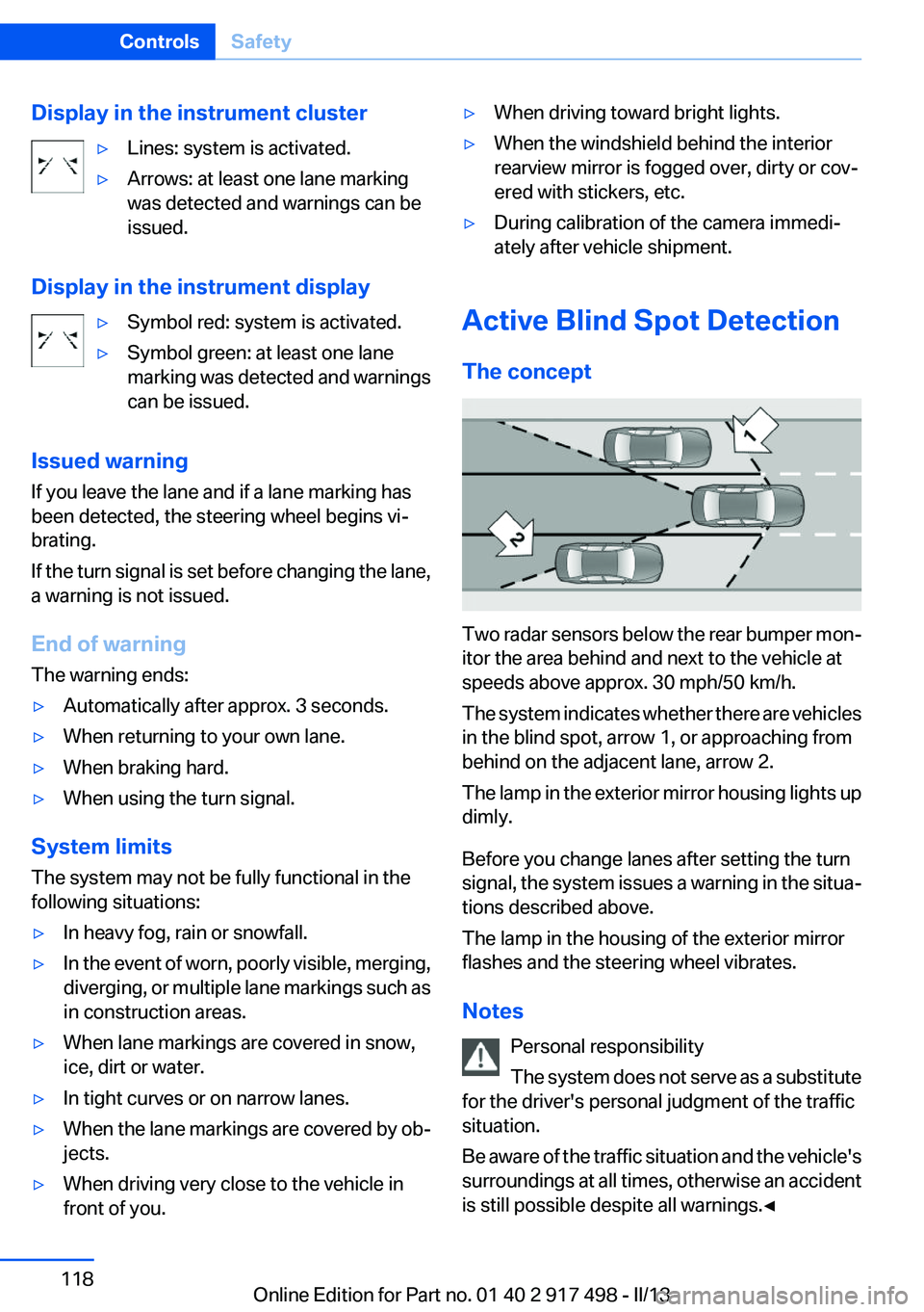
Two radar sensors below the rear bumper mon‐
itor the area behind and next to the vehicle at
speeds above approx. 30 mph/50 km/h.
The system indicates whether there are vehicles
in the blind spot, arrow 1, or approaching from
behind on the adjacent lane, arrow 2.
The lamp in the exterior mirror housing lights up
dimly.
Before you change lanes after setting the turn
signal, the system issues a warning in the situa‐
tions described above.
The lamp in the housing of the exterior mirror
flashes and the steering wheel vibrates.
Notes Personal responsibility
The system does not serve as a substitute
for the driver's personal judgment of the traffic
situation.
Be aware of the traffic situation and the vehicle's
surroundings at all times, otherwise an accident
is still possible despite all warnings.◀
Seite 118ControlsSafety118
Online Edition for Part no. 01 40 2 917 498 - II/13
Page 144 of 240
Switch the system back on if necessary.
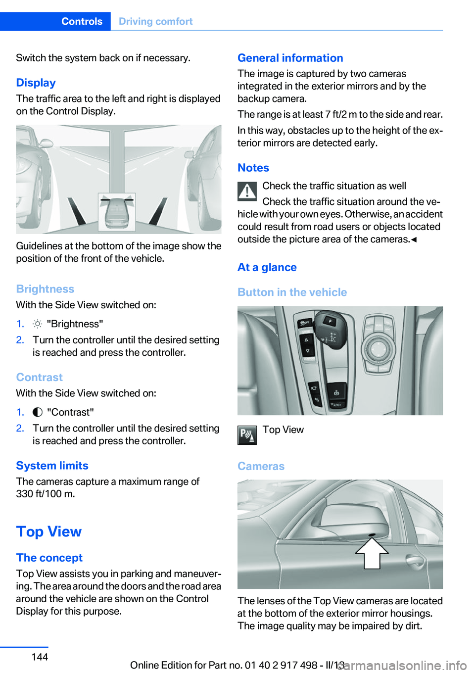
Display
The traffic area to the left and right is displayed
on the Control Display.
Guidelines at the bottom of the image show the
position of the front of the vehicle.
Brightness
With the Side View switched on:
1. "Brightness"2.Turn the controller until the desired setting
is reached and press the controller.
Contrast
With the Side View switched on:
1. "Contrast"2.Turn the controller until the desired setting
is reached and press the controller.
System limits
The cameras capture a maximum range of
330 ft/100 m.
Top View
The concept
Top View assists you in parking and maneuver‐
ing. The area around the doors and the road area
around the vehicle are shown on the Control
Display for this purpose.
General information
The image is captured by two cameras
integrated in the exterior mirrors and by the
backup camera.
The range is at least 7 ft/2 m to the side and rear.
In this way, obstacles up to the height of the ex‐
terior mirrors are detected early.
Notes Check the traffic situation as well
Check the traffic situation around the ve‐
hicle with your own eyes. Otherwise, an accident
could result from road users or objects located
outside the picture area of the cameras.◀
At a glance
Button in the vehicle
Top View
Cameras
The lenses of the Top View cameras are located
at the bottom of the exterior mirror housings.
The image quality may be impaired by dirt.
Seite 144ControlsDriving comfort144
Online Edition for Part no. 01 40 2 917 498 - II/13
Page 159 of 240
Interior equipmentVehicle equipment
All standard, country-specific and optional
equipment that is offered in the model series is
described in this chapter. Therefore, equipment
is also described that is not available in a vehicle,
e. g., because of the selected optional equip‐
ment or country variant. This also applies for
safety-related functions and systems.
Integrated universal remote
control
The concept
The integrated universal remote control can op‐
erate up to 3 functions of remote-controlled sys‐
tems such as garage door drives or lighting sys‐
tems. The integrated universal remote control
replaces up to 3 different hand-held transmit‐
ters. To operate the remote control, the buttons
on the interior rearview mirror must be program‐
med with the desired functions. The hand-held
transmitter for the particular system is required
in order to program the remote control.
During programming
During programming and before activat‐
ing a device using the integrated universal re‐
mote control, ensure that there are no people,
animals, or objects in the range of movement of
the remote-controlled device; otherwise, there
is a risk of injury or damage.
Also follow the safety instructions of the hand-
held transmitter.◀
Before selling the vehicle, delete the stored
functions for the sake of security.
Compatibility If this symbol is printed on the packaging
or in the instructions of the system to be
controlled, the system is generally com‐patible with the integrated universal remote
control.
If you have any questions, please contact:▷Your service center.▷www.homelink.com on the Internet.
HomeLink is a registered trademark of Johnson
Controls, Inc.
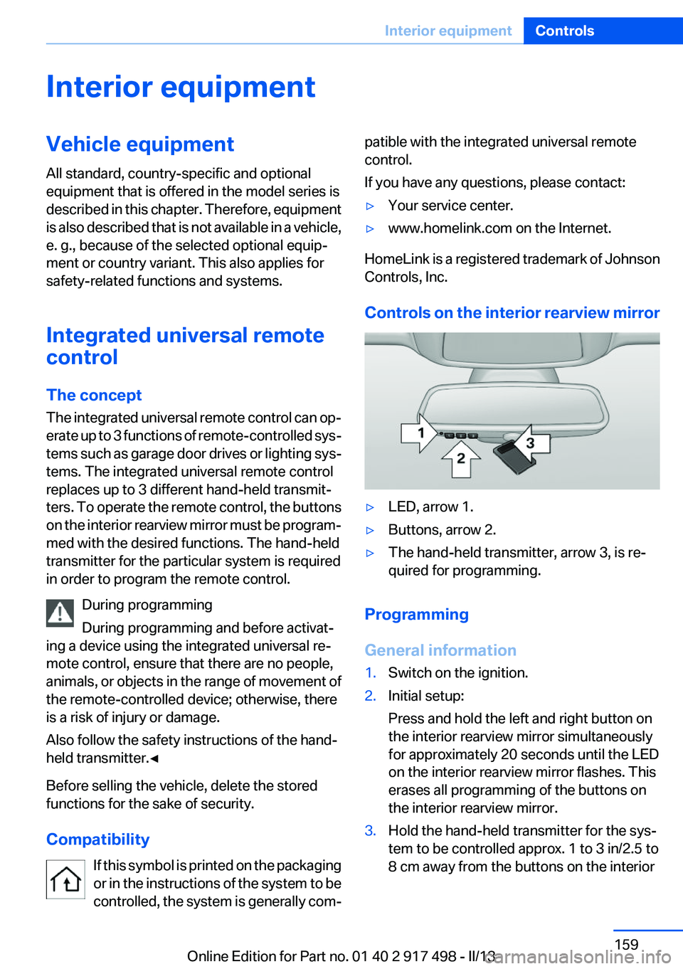
Controls on the interior rearview mirror
▷LED, arrow 1.▷Buttons, arrow 2.▷The hand-held transmitter, arrow 3, is re‐
quired for programming.
Programming
General information
1.Switch on the ignition.2.Initial setup:
Press and hold the left and right button on
the interior rearview mirror simultaneously
for approximately 20 seconds until the LED
on the interior rearview mirror flashes. This
erases all programming of the buttons on
the interior rearview mirror.3.Hold the hand-held transmitter for the sys‐
tem to be controlled approx. 1 to 3 in/2.5 to
8 cm away from the buttons on the interiorSeite 159Interior equipmentControls159
Online Edition for Part no. 01 40 2 917 498 - II/13
Page 160 of 240
rearview mirror. The required distance de‐
pends on the manual transmitter.4.Simultaneously press and hold the button of
the desired function on the hand-held trans‐
mitter and the button to be programmed on
the interior rearview mirror. The LED on the
interior rearview mirror will begin flashing
slowly.5.Release both buttons as soon as the LED
flashes more rapidly. When the LED is flash‐
ing faster, this indicates that the button on
the interior rearview mirror has been pro‐
grammed.
If the LED does not flash faster after at least
60 seconds, change the distance between
the interior rearview mirror and the hand-
held transmitter and repeat the step. Several
more attempts at different distances may be
necessary. Wait at least 15 seconds be‐
tween attempts.
Canada: if programming with the hand-held
transmitter was interrupted, hold down the
interior rearview mirror button and repeat‐
edly press and release the hand-held trans‐
mitter button for 2 seconds.6.To program other functions on other but‐
tons, repeat steps 3 to 5.
The systems can be controlled using the interior
rearview mirror buttons.
Special feature of the alternating-code
wireless system
If you are unable to operate the system after re‐
peated programming, please check if the sys‐
tem to be controlled features an alternating-
code system.
Read the system's operating manual, or press
the programmed button on the interior rearview
mirror longer. If the LED on the interior rearview
mirror starts flashing rapidly and then stays lit
constantly for 2 seconds, the system features
an alternating-code system. Flashing and con‐
tinuous illumination of the LED will repeat for
approximately 20 seconds.
For systems with an alternating-code system,
the integrated universal remote control and the
system also have to be synchronized.
Please read the operating manual of the system
being set up for information on how to syn‐
chronize the system.
Synchronizing is easier with the aid of a second
person.
To synchronize:1.Park the vehicle within range of the remote-
controlled system.2.Program the relevant button on the interior
rearview mirror as described.3.Locate and press the synchronizing button
on the system being programmed. You have
approx. 30 seconds for the next step.4.Hold down the programmed button on the
interior rearview mirror for approximately
3 seconds and then release it. If necessary,
repeat this work step up to three times in or‐
der to finish synchronization. Once synchro‐
nization is complete, the programmed func‐
tion will be carried out.
Reprogramming individual buttons
1.Switch on the ignition.2.Press and hold the interior rearview mirror
button to be programmed.3.As soon as the interior rearview mirror LED
starts flashing slowly, hold the hand-held
transmitter for the system to be controlled
approx. 1 to 3 in/2.5 to 8 cm away from the
buttons on the interior rearview mirror. The
required distance depends on the manual
transmitter.4.Likewise, press and hold the button of the
desired function on the hand-held transmit‐
ter.5.Release both buttons as soon as the interior
rearview mirror LED flashes more rapidly.
When the LED is flashing faster, this indi‐
cates that the button on the interior rearview
mirror has been programmed. The systemSeite 160ControlsInterior equipment160
Online Edition for Part no. 01 40 2 917 498 - II/13
Page 161 of 240
can then be controlled by the button on the
interior rearview mirror.
If the LED does not flash faster after at least
60 seconds, change the distance and repeat
the step. Several more attempts at different
distances may be necessary. Wait at least
15 seconds between attempts.
Canada: if programming with the hand-held
transmitter was interrupted, hold down the
interior rearview mirror button and repeat‐
edly press and release the hand-held trans‐
mitter button for 2 seconds.
Controls
Before operation
Before operating a system using the
integrated universal remote control, ensure that
there are no people, animals, or objects within
the range of movement of the remote-controlled
system; otherwise, there is a risk of injury or
damage.
Also follow the safety instructions of the hand-
held transmitter.◀
The system, such as the garage door, can be
operated using the button on the interior rear‐
view mirror while the engine is running or when
the ignition is started. To do this, hold down the
button within receiving range of the system until
the function is activated. The interior rearview
mirror LED stays lit while the wireless signal is
being transmitted.
Deleting stored functions
Press and hold the left and right button on the
interior rearview mirror simultaneously for ap‐
proximately 20 seconds until the LED flashes
rapidly. All stored functions are deleted. The
functions cannot be deleted individually.
Ashtray/cigarette lighter
Front
Opening
Press on the cover.
Emptying
Take out the insert.
Lighter Push in the lighter.
The lighter can be removed as
soon as it pops back out.
Danger of burns
Only hold the hot lighter by its knob; oth‐
erwise, there is the danger of getting burned.
Switch off the ignition and take the remote con‐
trol with you when leaving the vehicle so that
children cannot use the lighter and burn them‐
selves.◀
Seite 161Interior equipmentControls161
Online Edition for Part no. 01 40 2 917 498 - II/13
Page 232 of 240

Controller 16
Control systems, driving sta‐ bility 122
Convenient opening 35
Coolant 205
Coolant temperature 88
Cooling function 154
Cooling, maximum 153
Cooling system 205
Corrosion on brake discs 176
Cruise control 136
Cruise control, active with Stop & Go 130
Cruising range 89
Cupholder 169
Curb weight 227
Current fuel consumption 89
D
Damage, tires 196
Damping control, dy‐ namic 125
Data, technical 226
Date 89
Daytime running lights 98
Defrosting, refer to Windows, defrosting 153
Dehumidifying, air 154
Destination distance 93
Digital clock 88
Dimensions 226
Dimmable exterior mirrors 61
Dimmable interior rearview mirror 61
Direction indicator, refer to Turn signals 75
Display in windshield 150
Display lighting, refer to Instru‐ ment lighting 100
Displays 81, 82
Displays, cleaning 223
Disposal, vehicle battery 213
Distance control, refer to PDC 138 Distance, selecting for
ACC 132
Distance to destination 93
Divided screen view, split screen 20
Door lock, refer to Remote control 30
Doors, Automatic Soft Clos‐ ing 38
Downhill control 124
Drive-off assistant 122
Drive-off assistant, refer to DSC 122
Driving Dynamics Control 127
Driving instructions, breaking in 174
Driving mode 127
Driving notes, general 174
Driving stability control sys‐ tems 122
Driving tips 174
DSC Dynamic Stability Con‐ trol 122
DTC driving dynamics 123
DTC Dynamic Traction Con‐ trol 123
Dynamic Damping Con‐ trol 125
Dynamic Drive 125
Dynamic Stability Control DSC 122
Dynamic Traction Control DTC 123
E
ECO PRO 181
ECO PRO, bonus range 182
ECO PRO display 181
ECO PRO driving mode 181
ECO PRO mode 181
ECO PRO Tip - driving instruc‐ tion 183
EfficientDynamics 183
Electronic displays, instru‐ ment cluster 82 Electronic Stability Program
ESP, refer to DSC 122
Emergency detection, remote control 31
Emergency release, door lock 37
Emergency release, fuel filler flap 188
Emergency release, parking brake 72
Emergency Request 215
Emergency service, refer to Roadside Assistance 216
Emergency start function, en‐ gine start 31
Emergency unlocking, tail‐ gate 41
Energy Control 89
Energy recovery 89
Engine, automatic Start/Stop function 70
Engine, automatic switch- off 70
Engine compartment 201
Engine compartment, working in 201
Engine coolant 205
Engine oil 203
Engine oil, adding 204
Engine oil additives 204
Engine oil change 204
Engine oil filler neck 204
Engine oil temperature 88
Engine oil types, alterna‐ tive 204
Engine oil types, ap‐ proved 204
Engine start during malfunc‐ tion 31
Engine start, jump-start‐ ing 217
Engine start, refer to Starting the engine 69
Engine stop 69
Engine temperature 88
Entering a car wash 220 Seite 232ReferenceEverything from A to Z232
Online Edition for Part no. 01 40 2 917 498 - II/13
Page 234 of 240
Ignition off 68
Ignition on 68
Indication of a flat tire 106 , 108
Individual air distribution 153
Individual settings, refer to Personal Profile 31
Inflation pressure, tires 191
Inflation pressure warning FTM, tires 105
Info display, refer to Com‐ puter 92
Initialization, Integral Active Steering 126
Initialize, Tire Pressure Moni‐ tor TPM 108
Initializing, Flat Tire Monitor FTM 105
Instrument cluster 81
Instrument cluster, electronic displays 82
Instrument display, multifunc‐ tional 82
Instrument lighting 100
Integral Active Steering 125
Integrated key 30
Integrated universal remote control 159
Intensity, AUTO program 153
Interior equipment 159
Interior lamps 101
Interior lamps via remote con‐ trol 35
Interior motion sensor 44
Interior rearview mirror 61
Interior rearview mirror, auto‐ matic dimming feature 61
Internet page 6
Interval display, service re‐ quirements 89
J
Jacking points for the vehicle jack 212
Jack, refer to Vehicle jack 212 Joystick, automatic transmis‐
sion 79
Jump-starting 217
K
Key/remote control 30
Keyless Go, refer to Comfort Access 41
Key Memory, refer to Personal Profile 31
Kickdown, automatic trans‐ mission 79
Knee airbag 102
L
Lamp replacement 208
Lamp replacement, rear 211
Lamps 97
Lamps and bulbs 208
Lane departure warning 117
Lane margin, warning 117
Language on Control Dis‐ play 95
Lashing eyes, securing cargo 178
LATCH child restraint fixing system 64
Leather, care 221
LEDs, light-emitting di‐ odes 209
Length, vehicle 227
Letters and numbers, enter‐ ing 21
License plate lamp, bulb re‐ placement 211
Light-alloy wheels, care 222
Light control 99
Light-emitting diodes, LEDs 209
Lighting 97
Lighting, speaker 101
Lighting via remote control 35
Light switch 97
Load 177 Loading 177
Loading position 166
Lock, door 36
Locking/unlocking from in‐ side 37
Locking/unlocking via door lock 36
Locking/unlocking with re‐ mote control 34
Locking, automatic 37
Locking, central 34
Locking via tailgate 39
Lock, power window 46
Locks, doors, and win‐ dows 67
Low beams 97
Low beams, automatic, refer to High-beam Assistant 99
Lower back support 51
Luggage rack, refer to Roof- mounted luggage rack 178
Lumbar support 51
M
Maintenance 206
Maintenance require‐ ments 206
Maintenance, service require‐ ments 89
Maintenance system, BMW 206
Malfunction displays, refer to Check Control 85
Malfunction, self-leveling sus‐ pension 126
Manual air distribution 153
Manual air flow 153
Manual brake, refer to Parking brake 72
Manual mode, transmis‐ sion 80
Manual operation, backup camera 141
Manual operation, door lock 37 Seite 234ReferenceEverything from A to Z234
Online Edition for Part no. 01 40 2 917 498 - II/13