2013 BMW 335I check engine light
[x] Cancel search: check engine lightPage 44 of 242

If desired, continue the movement by pressing
the switch.
Pinch protection system
If the closing force when closing the glass sun‐
roof exceeds a certain value, the closing move‐
ment is stopped, beginning at approximately the
middle of the opening in the roof, or from the
tilted position during closing.
The glass sunroof opens again slightly.
Danger of pinching even with pinch pro‐
tection
Despite the pinch protection system, check that
the roof's closing path is clear; otherwise, the
closing action may not be interrupted in certain
extreme situations, such as when thin objects
are present.◀
Closing from the open position without
pinch protection
For example, if there is an external danger, pro‐
ceed as follows:1.Press the switch forward beyond the resist‐
ance point and hold.
Pinch protection is limited and the roof re‐
opens slightly if the closing force exceeds a
certain value.2.Press the switch forward again beyond the
resistance point and hold until the roof
closes without pinch protection.
Closing from the raised position
without pinch protection
If there is an external danger, push the switch
forward past the resistance point and hold it.
The roof closes without pinch protection.
Initializing after a power failure
After a power failure during the opening or clos‐
ing process, the roof can only be operated to a
limited extent.
Initializing the system
The system can be initialized when the vehicle
is stationary and the engine is running.
During the initialization, the roof closes without
pinch protection.
Keep the closing path clear
Monitor the closing process and make
sure that the closing path of the glass sunroof is
clear; otherwise, injuries may result.◀
Press the switch up and hold it
until the initialization is complete:▷Initialization begins within
15 seconds and is completed
when the sunroof is com‐
pletely closed.▷The roof closes without pinch protection.Seite 44ControlsOpening and closing44
Online Edition for Part no. 01 40 2 917 801 - II/13
Page 63 of 242
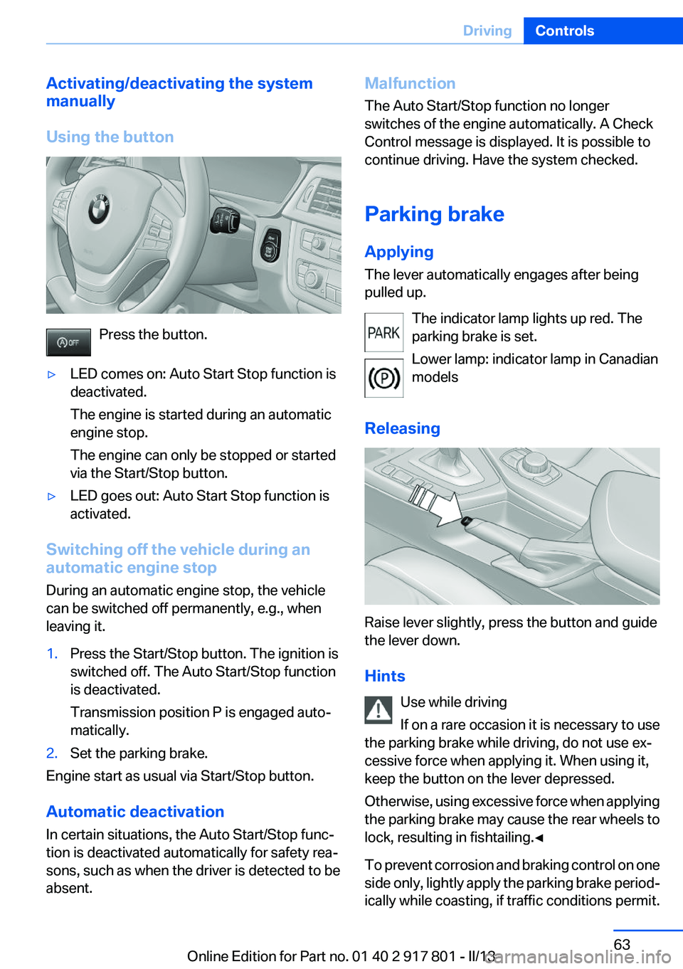
Activating/deactivating the system
manually
Using the button
Press the button.
▷LED comes on: Auto Start Stop function is
deactivated.
The engine is started during an automatic
engine stop.
The engine can only be stopped or started
via the Start/Stop button.▷LED goes out: Auto Start Stop function is
activated.
Switching off the vehicle during an
automatic engine stop
During an automatic engine stop, the vehicle
can be switched off permanently, e.g., when
leaving it.
1.Press the Start/Stop button. The ignition is
switched off. The Auto Start/Stop function
is deactivated.
Transmission position P is engaged auto‐
matically.2.Set the parking brake.
Engine start as usual via Start/Stop button.
Automatic deactivation
In certain situations, the Auto Start/Stop func‐
tion is deactivated automatically for safety rea‐
sons, such as when the driver is detected to be
absent.
Malfunction
The Auto Start/Stop function no longer
switches of the engine automatically. A Check
Control message is displayed. It is possible to
continue driving. Have the system checked.
Parking brake
Applying
The lever automatically engages after being
pulled up.
The indicator lamp lights up red. The
parking brake is set.
Lower lamp: indicator lamp in Canadian
models
Releasing
Raise lever slightly, press the button and guide
the lever down.
Hints Use while driving
If on a rare occasion it is necessary to use
the parking brake while driving, do not use ex‐
cessive force when applying it. When using it,
keep the button on the lever depressed.
Otherwise, using excessive force when applying
the parking brake may cause the rear wheels to
lock, resulting in fishtailing.◀
To prevent corrosion and braking control on one
side only, lightly apply the parking brake period‐
ically while coasting, if traffic conditions permit.
Seite 63DrivingControls63
Online Edition for Part no. 01 40 2 917 801 - II/13
Page 74 of 242
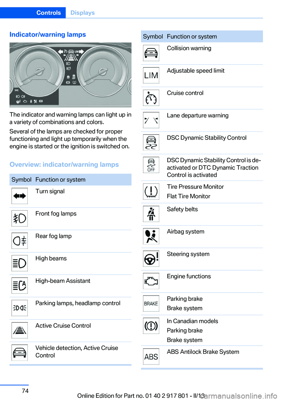
Indicator/warning lamps
The indicator and warning lamps can light up in
a variety of combinations and colors.
Several of the lamps are checked for proper
functioning and light up temporarily when the
engine is started or the ignition is switched on.
Overview: indicator/warning lamps
SymbolFunction or systemTurn signalFront fog lampsRear fog lampHigh beamsHigh-beam AssistantParking lamps, headlamp controlActive Cruise ControlVehicle detection, Active Cruise
ControlSymbolFunction or systemCollision warningAdjustable speed limitCruise controlLane departure warningDSC Dynamic Stability ControlDSC Dynamic Stability Control is de‐
activated or DTC Dynamic Traction
Control is activatedTire Pressure Monitor
Flat Tire MonitorSafety beltsAirbag systemSteering systemEngine functionsParking brake
Brake systemIn Canadian models
Parking brake
Brake systemABS Antilock Brake SystemSeite 74ControlsDisplays74
Online Edition for Part no. 01 40 2 917 801 - II/13
Page 96 of 242
One wheel is yellow
A flat tire or major drop in inflation pressure in
the indicated tire.
All wheels are yellow
A flat tire or major drop in inflation pressure in
several tires.
Wheels, gray
The system cannot detect a flat tire. Reasons for
this may be:▷The system is being reset.▷Malfunction.
Carry out reset
Reset the system after each correction of the
tire inflation pressure and after every tire or
wheel change.
1."Vehicle Info"2."Vehicle status"3. "Reset"4.Start the engine - do not drive away.5.Carry out the reset with "Reset".6.Drive away.
The tires are shown in gray and the status is dis‐
played.
After driving faster than 19 mph/30 km/h for a
short period, the tire inflation pressures set are
accepted as reference values. The reset is com‐
pleted automatically during driving. After suc‐
cessful completion of the reset, the tires appear
in green on the Control Display and "TPM
active" is displayed.
The trip can be interrupted at any time. If you
drive away again, the reset resumes automati‐
cally.
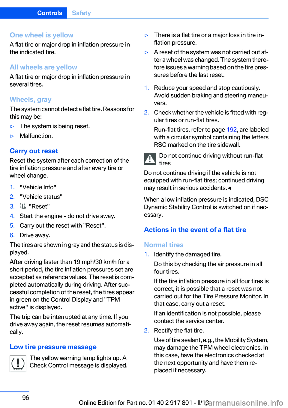
Low tire pressure message The yellow warning lamp lights up. A
Check Control message is displayed.
▷There is a flat tire or a major loss in tire in‐
flation pressure.▷A reset of the system was not carried out af‐
ter a wheel was changed. The system there‐
fore issues a warning based on the tire pres‐
sures before the last reset.1.Reduce your speed and stop cautiously.
Avoid sudden braking and steering maneu‐
vers.2.Check whether the vehicle is fitted with reg‐
ular tires or run-flat tires.
Run-flat tires, refer to page 192, are labeled
with a circular symbol containing the letters
RSC marked on the tire sidewall.
Do not continue driving without run-flat
tires
Do not continue driving if the vehicle is not
equipped with run-flat tires; continued driving
may result in serious accidents.◀
When a low inflation pressure is indicated, DSC
Dynamic Stability Control is switched on if nec‐
essary.
Actions in the event of a flat tire
Normal tires
1.Identify the damaged tire.
Do this by checking the air pressure in all
four tires.
If the tire inflation pressure in all four tires is
correct, it is possible that a reset was not
carried out for the Tire Pressure Monitor. In
that case, carry out a reset.
If an identification is not possible, please
contact the service center.2.Rectify the flat tire.
Use of tire sealant, e.g., the Mobility System,
may damage the TPM wheel electronics. In
this case, have the electronics checked at
the next opportunity and have them re‐
placed if necessary.Seite 96ControlsSafety96
Online Edition for Part no. 01 40 2 917 801 - II/13
Page 99 of 242

2."Vehicle status"3. "Flat Tire Monitor"
The status is displayed.
Initialization
The initialization process adopts the set inflation
tire pressures as reference values for the detec‐
tion of a flat tire. Initialization is started by con‐
firming the inflation pressures.
Do not initialize the system when driving with
snow chains.
1."Vehicle Info"2."Vehicle status"3. "Reset"4.Start the engine - do not drive away.5.Start the initialization with "Reset".6.Drive away.
The initialization is completed while driving,
which can be interrupted at any time.
The initialization automatically continues when
driving resumes.
Indication of a flat tire The yellow warning lamp lights up. A
Check Control message is displayed.
There is a flat tire or a major loss in tire
inflation pressure.
1.Reduce your speed and stop cautiously.
Avoid sudden braking and steering maneu‐
vers.2.Check whether the vehicle is fitted with reg‐
ular tires or run-flat tires.
Run-flat tires, refer to page 192, are labeled
with a circular symbol containing the letters
RSC marked on the tire sidewall.
Do not continue driving without run-flat
tires
Do not continue driving if the vehicle is not
equipped with run-flat tires; continued driving
may result in serious accidents.◀
When a flat tire is indicated, DSC Dynamic Sta‐
bility Control is switched on if necessary.
System limits Sudden tire damage
Sudden serious tire damage caused by
external influences cannot be indicated in ad‐
vance.◀
A natural, even pressure loss in all four tires can‐
not be detected. Therefore, check the tire infla‐
tion pressure regularly.
The system could be delayed or malfunction in
the following situations:▷When the system has not been initialized.▷When driving on a snowy or slippery road
surface.▷Sporty driving style: slip in the drive wheels,
high lateral acceleration.▷When driving with snow chains.
Actions in the event of a flat tire
Normal tires
1.Identify the damaged tire.
Do this by checking the air pressure in all
four tires.
If the tire inflation pressure in all four tires is
correct, the Flat Tire Monitor may not have
been initialized. In this case, initialize the
system.
If an identification is not possible, please
contact the service center.2.Rectify the flat tire.
Run-flat tires
Maximum speed
You can continue driving with a damaged tire at
speeds up to 50 mph/80 km/h.
Seite 99SafetyControls99
Online Edition for Part no. 01 40 2 917 801 - II/13
Page 107 of 242
A Check Control message is displayed when the
system is not fully functional.
For US owners only
The transmitter and receiver units comply with
part 15 of the FCC/Federal Communication
Commission regulations. Operation is governed
by the following:
FCC ID:▷NBG009014A.
Compliance statement:
This device complies with part 15 of the FCC
Rules. Operation is subject to the following two
conditions:
▷This device may not cause harmful interfer‐
ence, and▷this device must accept any interference re‐
ceived, including interference that may
cause undesired operation.
Any unauthorized modifications or changes to
these devices could void the user's authority to
operate this equipment.
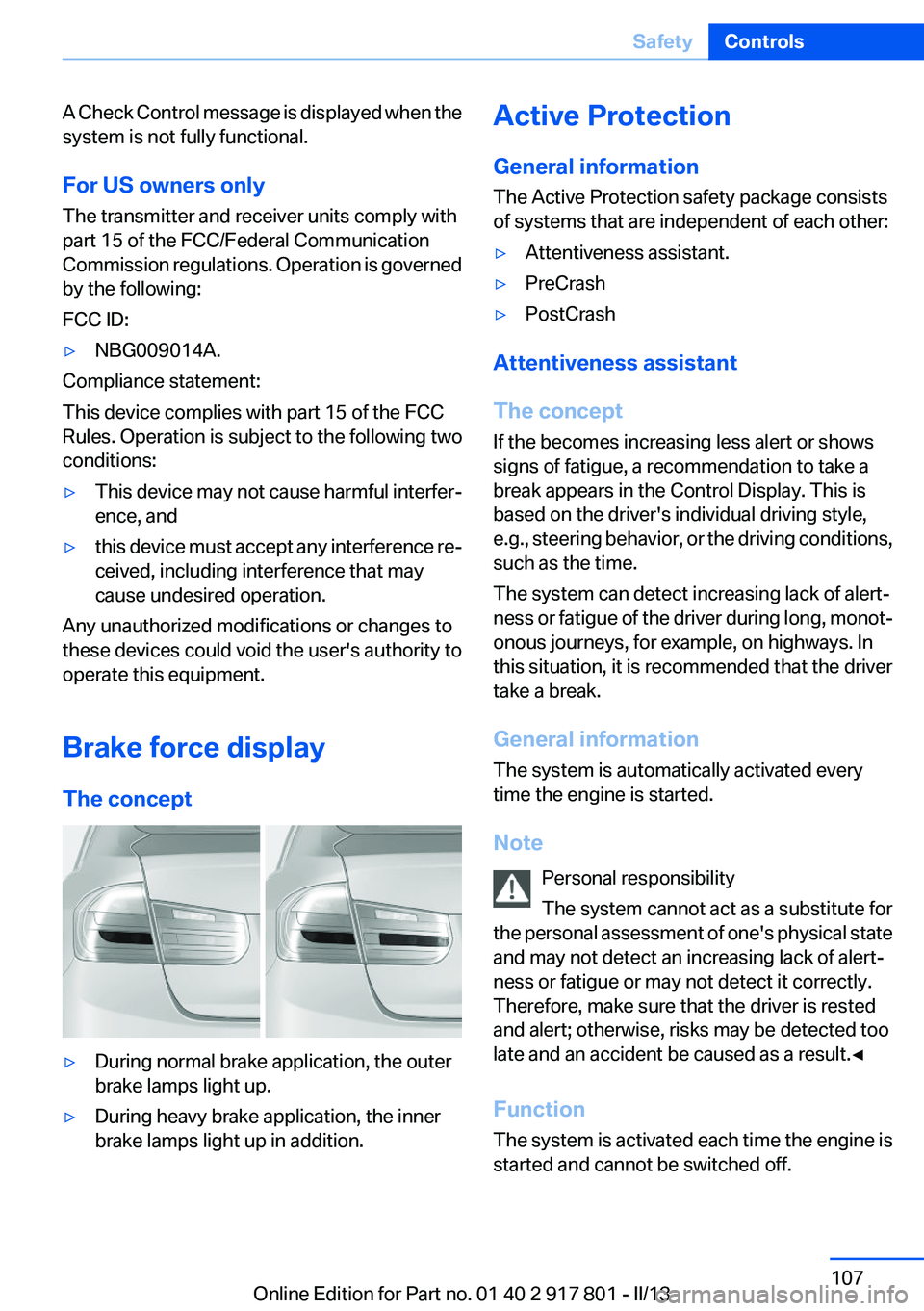
Brake force display
The concept
▷During normal brake application, the outer
brake lamps light up.▷During heavy brake application, the inner
brake lamps light up in addition.Active Protection
General information
The Active Protection safety package consists
of systems that are independent of each other:▷Attentiveness assistant.▷PreCrash▷PostCrash
Attentiveness assistant
The concept
If the becomes increasing less alert or shows
signs of fatigue, a recommendation to take a
break appears in the Control Display. This is
based on the driver's individual driving style,
e.g., steering behavior, or the driving conditions,
such as the time.
The system can detect increasing lack of alert‐
ness or fatigue of the driver during long, monot‐
onous journeys, for example, on highways. In
this situation, it is recommended that the driver
take a break.
General information
The system is automatically activated every
time the engine is started.
Note Personal responsibility
The system cannot act as a substitute for
the personal assessment of one's physical state
and may not detect an increasing lack of alert‐
ness or fatigue or may not detect it correctly.
Therefore, make sure that the driver is rested
and alert; otherwise, risks may be detected too
late and an accident be caused as a result.◀
Function
The system is activated each time the engine is
started and cannot be switched off.
Seite 107SafetyControls107
Online Edition for Part no. 01 40 2 917 801 - II/13
Page 118 of 242
While standingBefore leaving the vehicle, secure it
against rolling.
Before leaving the vehicle with the engine run‐
ning, engage position P of the automatic trans‐
mission and apply the parking brake. Otherwise,
the vehicle may begin to roll.◀
The system brought the vehicle to a complete
standstill:▷Green marking in the speedometer:
Your vehicle accelerates automatically as
soon as the vehicle in the range of the radar
sensor moves off.▷Marking in the speedometer turns orange:
no automatic driving away.
To accelerate to the desired speed auto‐
matically, press the accelerator briefly or
press the RES or SET button.
Rolling bars in the distance display indicate that
the vehicle in the radar sensor detection range
has moved off.
Your vehicle was braked to a halt by pressing on
the brake pedal and it is standing behind another
vehicle:
1. Press the button to call up a stored
desired speed.2.Release the brake pedal.3.Press on the accelerator briefly, or press the
RES button or the rocker switch when the
vehicle ahead of you drives away.
Displays in the instrument cluster
Desired speed
▷The marking lights up green:
the system is active.▷The marking lights up or‐
ange: the system has been
interrupted.▷The marking does not light up: the system is
switched off.
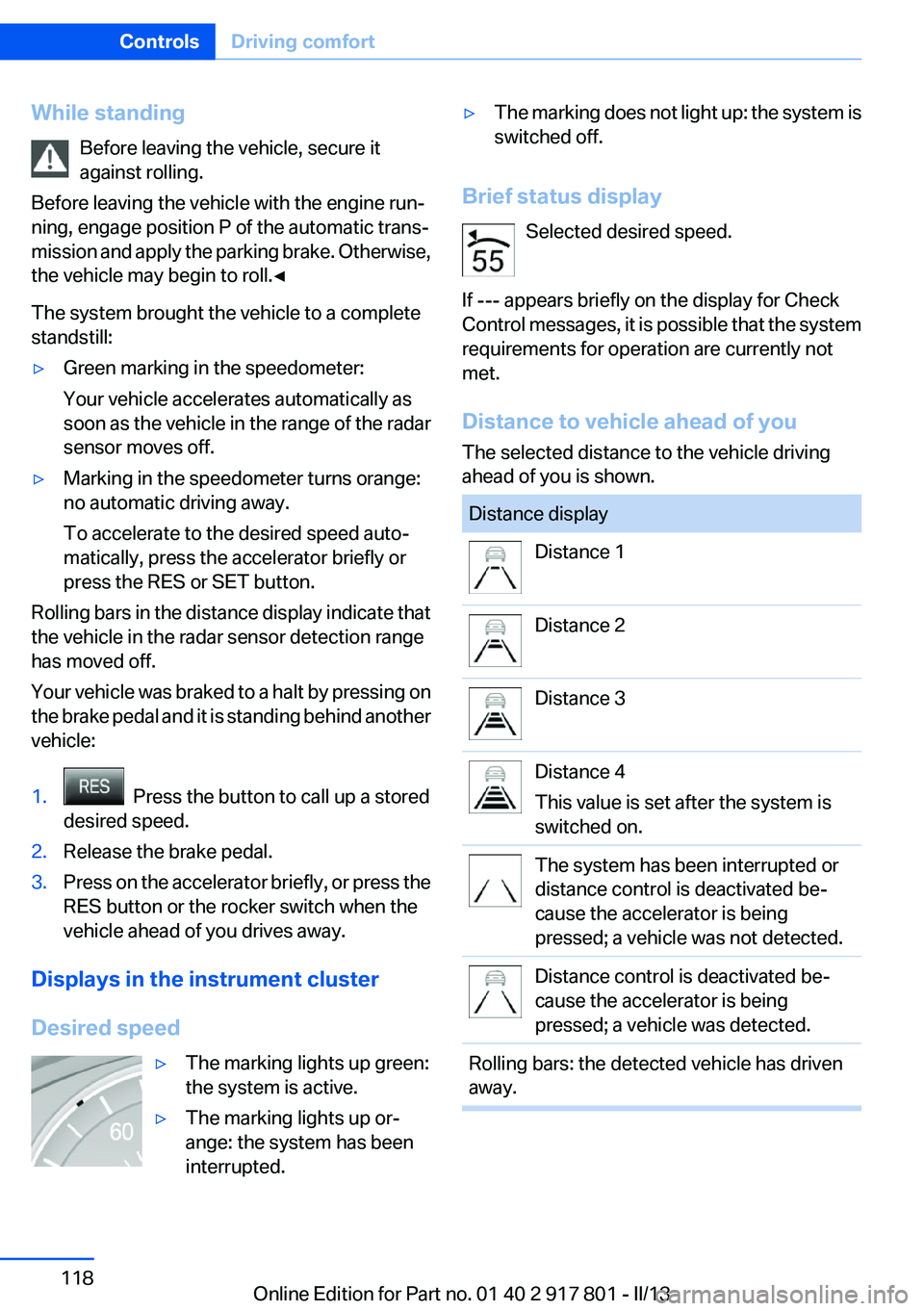
Brief status display
Selected desired speed.
If --- appears briefly on the display for Check
Control messages, it is possible that the system
requirements for operation are currently not
met.
Distance to vehicle ahead of you
The selected distance to the vehicle driving
ahead of you is shown.
Distance displayDistance 1Distance 2Distance 3Distance 4
This value is set after the system is
switched on.The system has been interrupted or
distance control is deactivated be‐
cause the accelerator is being
pressed; a vehicle was not detected.Distance control is deactivated be‐
cause the accelerator is being
pressed; a vehicle was detected.Rolling bars: the detected vehicle has driven
away.Seite 118ControlsDriving comfort118
Online Edition for Part no. 01 40 2 917 801 - II/13
Page 126 of 242
NotesCheck the traffic situation as well
Check the traffic situation around the ve‐
hicle with your own eyes. Otherwise, an accident
could result from road users or objects located
outside the picture area of the backup camera. ◀
At a glance
Button in the vehicle
Backup camera
Camera
The camera lens is located in the handle of the
trunk lid. The image quality may be impaired by
dirt.
Clean the lens, refer to page 222.
Switching on/off
Switching on automatically
Select transmission position R with the engine
running.
The backup camera image is displayed if the
system was switched on via the iDrive.
Automatic deactivation during forward
travel
The system switches off when a certain driving
distance or speed is exceeded.
Switch the system back on if necessary.
Switching on/off manually Press the button.▷On: the LED lights up.▷Off: the LED goes out.
The PDC is shown on the Control Display.
Switch on the backup camera via the iDrive, refer
to page 124.
Switching on the backup camera via the
iDrive
With PDC activated:
"Rear view camera"
The backup camera image is displayed. The set‐
ting is stored for the remote control currently in
use.
Display on the Control Display
Functional requirement
▷The backup camera is switched on.▷The trunk lid is fully closed.
Activating the assistance functions
More than one assistance function can be active
at the same time.
▷Parking aid lines
"Parking aid lines"
Pathway and turning circle lines are dis‐
played.
▷Obstacle marking
"Obstacle marking"
Seite 126ControlsDriving comfort126
Online Edition for Part no. 01 40 2 917 801 - II/13