2013 BMW 335I ECU
[x] Cancel search: ECUPage 195 of 242

Hood
Hints Working in the engine compartment
Never attempt to perform any service or
repair operations on your vehicle without the
necessary professional technical training.
If you are unfamiliar with the statutory guide‐
lines, have any work on the vehicle performed
only by a service center.
If this work is not carried out properly, there is
the danger of subsequent damage and related
safety hazards.◀
Never reach into the engine compartment
Never reach into the intermediate spaces
or gaps in the engine compartment. Otherwise,
there is risk of injury, e.g. from rotating or hot
parts.◀
Fold down wiper arm
Before opening the hood, ensure that the
wiper arms are against the windshield, or this
may result in damage.◀
Opening the hood1.Pull lever in the interior:
Engine is released, arrow 1.2.After the lever is released, pull the lever
again:
Hood can be opened, arrow 2.Indicator/warning lamps
When the hood is opened, a Check Control mes‐
sage is displayed.
Closing the hood
Let the hood drop from a height of approx.
16 in/40 cm and push down on it to lock it fully.
The hood must audibly engage on both sides.
Hood open when driving
If you see any signs that the hood is not
completely closed while driving, pull over imme‐
diately and close it securely.◀
Danger of pinching
Make sure that the closing path of the
hood is clear; otherwise, injuries may result.◀
Seite 195Engine compartmentMobility195
Online Edition for Part no. 01 40 2 917 801 - II/13
Page 209 of 242

5.Remove the connecting line from the clip on
the bulb holder.6.Release the catch at the top on the connec‐
tor of the connecting line and remove the
connector from the bulb holder.
Replacing the bulbs
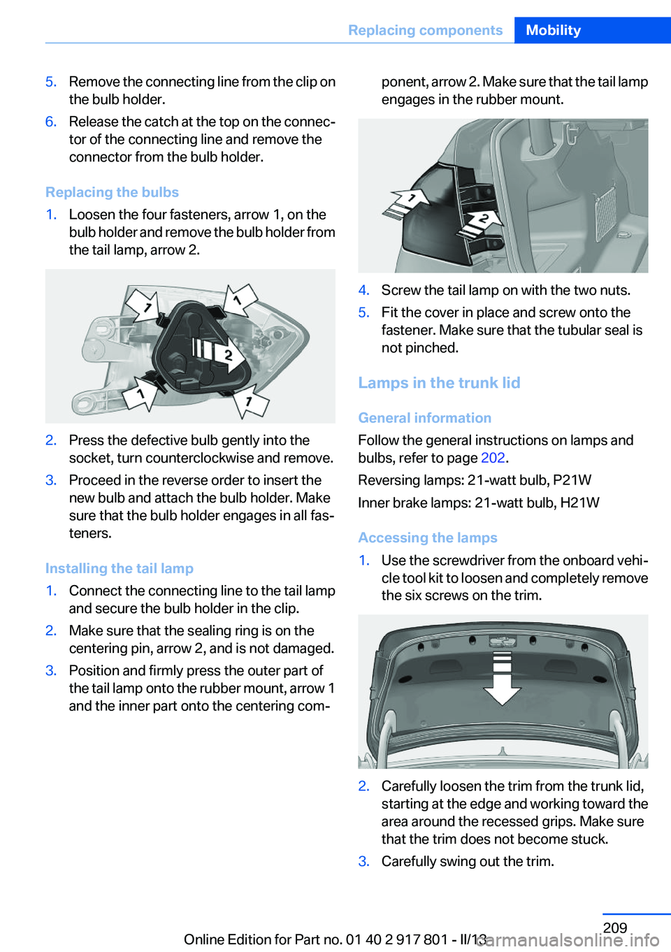
1.Loosen the four fasteners, arrow 1, on the
bulb holder and remove the bulb holder from
the tail lamp, arrow 2.2.Press the defective bulb gently into the
socket, turn counterclockwise and remove.3.Proceed in the reverse order to insert the
new bulb and attach the bulb holder. Make
sure that the bulb holder engages in all fas‐
teners.
Installing the tail lamp
1.Connect the connecting line to the tail lamp
and secure the bulb holder in the clip.2.Make sure that the sealing ring is on the
centering pin, arrow 2, and is not damaged.3.Position and firmly press the outer part of
the tail lamp onto the rubber mount, arrow 1
and the inner part onto the centering com‐ponent, arrow 2. Make sure that the tail lamp
engages in the rubber mount.4.Screw the tail lamp on with the two nuts.5.Fit the cover in place and screw onto the
fastener. Make sure that the tubular seal is
not pinched.
Lamps in the trunk lid
General information
Follow the general instructions on lamps and
bulbs, refer to page 202.
Reversing lamps: 21-watt bulb, P21W
Inner brake lamps: 21-watt bulb, H21W
Accessing the lamps
1.Use the screwdriver from the onboard vehi‐
cle tool kit to loosen and completely remove
the six screws on the trim.2.Carefully loosen the trim from the trunk lid,
starting at the edge and working toward the
area around the recessed grips. Make sure
that the trim does not become stuck.3.Carefully swing out the trim.Seite 209Replacing componentsMobility209
Online Edition for Part no. 01 40 2 917 801 - II/13
Page 210 of 242

Replacing the reversing lamp and inner
brake lamp1.Loosen the two fasteners, arrow 1 and pull
down on the lamp holder to remove, arrow 2.2.Press the defective bulb gently into the
socket, turn counterclockwise and remove.3.Insert the new bulb.
Installing the bulb holder
1.Slide the bulb holder onto the two guide
pins, arrow 1. Insert the two contacts, ar‐
row 2, into the connections, arrow 3.2.Press on the bulb holder. Make sure that the
two exterior fasteners latch into place.3.Swing the trim back onto the trunk lid and
secure.
Tail lamp, license plate lamp and
central brake lamp
Follow the general instructions on lamps and
bulbs, refer to page 202.
The lamps feature LED technology. Contact
your service center in the event of a malfunction.
Changing wheels
Notes
The vehicle equipment does not include a spare
tire.
When using run-flat tires or tire sealants, a tire
does not need to be changed immediately in the
event of pressure loss due to a flat tire.
The tools for changing wheels are available as
accessories from your service center.
Jacking points for the vehicle jack
The jacking points for the vehicle jack are lo‐
cated in the positions shown.
Vehicle battery
Maintenance
The battery is maintenance-free, i.e., the elec‐
trolyte will last for the life of the battery.
Your service center will be glad to advise you on
questions regarding the battery.
Battery replacement Use approved vehicle batteries only
Only use vehicle batteries that have been
approved for your vehicle by the manufacturer;
otherwise, the vehicle could be damaged and
systems or functions may not be fully availa‐
ble.◀
After a battery replacement, have the battery
registered on the vehicle by your service center
Seite 210MobilityReplacing components210
Online Edition for Part no. 01 40 2 917 801 - II/13
Page 211 of 242

to ensure that all comfort functions are fully
available and that any Check Control messages
are no longer displayed.
Charging the battery
Note Do not plug chargers into the socket
Do not connect battery chargers to the
factory-installed sockets in the vehicle as this
may damage the battery.◀
General information
Make sure that the battery is always sufficiently
charged to guarantee that the battery remains
usable for its full service life.
The battery may need to be charged in the fol‐
lowing cases:▷When making frequent short-distance
drives.▷If the vehicle is not used for prolonged peri‐
ods, longer than a month.
Starting aid terminals
In the vehicle, only charge the battery via the
starting aid terminals, refer to page 215, in the
engine compartment with the engine off.
Power failure
After a temporary power loss, some equipment
needs to be reinitialized.
Individual settings need to be reprogrammed:
▷Seat and mirror memory: store the positions
again.▷Time: update.▷Date: update.▷Radio station: save again.▷Navigation system: wait for the operability of
the navigation.Disposing of old batteries
Have old batteries disposed of by your
service center or bring them to a recy‐
cling center.
Maintain the battery in an upright position for
transport and storage. Secure the battery so
that it does not tip over during transport.
Fuses
Notes Replacing fuses
Never attempt to repair a blown fuse and
do not replace a defective fuse with a substitute
of another color or amperage rating; this could
lead to a circuit overload, ultimately resulting in
a fire in the vehicle.◀
Plastic tweezers and information on the fuse
types and locations are stored in the fuse box in
the cargo area.
In the engine compartment1.Use the onboard vehicle tool kit to loosen
the three cover screws, arrow 1.2.Pull up the holder, arrow 2.Seite 211Replacing componentsMobility211
Online Edition for Part no. 01 40 2 917 801 - II/13
Page 217 of 242

Do not lift the vehicle
Do not lift the vehicle by the tow fitting or
body and chassis parts; otherwise, damage may
result.◀
Towing other vehicles
General information Light towing vehicle
The towing vehicle must not be lighter
than the vehicle being towed; otherwise, it will
not be possible to control the vehicle re‐
sponse.◀
Attaching the tow bar/tow rope correctly
Attach the tow bar or tow rope to the tow
fitting; connecting it to other vehicle parts may
cause damage.◀▷Switch on the hazard warning system, de‐
pending on local regulations.▷If the electrical system has failed, clearly
identify the vehicle being towed by placing
a sign or a warning triangle in the rear win‐
dow.
Tow bar
The tow fittings used should be on the same
side on both vehicles.
Should it prove impossible to avoid mounting
the tow bar at an offset angle, please observe
the following:
▷Maneuvering capability is limited during cor‐
nering.▷The tow bar will generate lateral forces if it
is secured with an offset.
Tow rope
When starting to tow the vehicle, make sure that
the tow rope is taut.
To avoid jerking and the associated stresses on
the vehicle components when towing, always
use nylon ropes or nylon straps.
Attaching the tow rope correctly
Only secure the tow rope on the tow fit‐
ting; otherwise, damage can occur when it is se‐
cured on other parts of the vehicle.◀
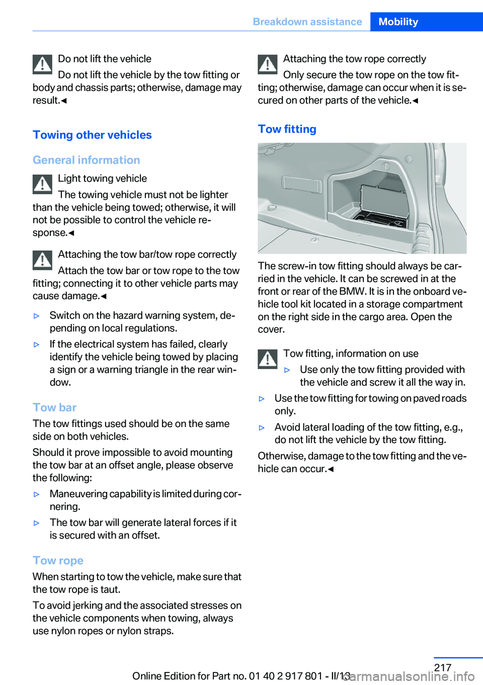
Tow fitting
The screw-in tow fitting should always be car‐
ried in the vehicle. It can be screwed in at the
front or rear of the BMW. It is in the onboard ve‐
hicle tool kit located in a storage compartment
on the right side in the cargo area. Open the
cover.
Tow fitting, information on use
▷Use only the tow fitting provided with
the vehicle and screw it all the way in.▷Use the tow fitting for towing on paved roads
only.▷Avoid lateral loading of the tow fitting, e.g.,
do not lift the vehicle by the tow fitting.
Otherwise, damage to the tow fitting and the ve‐
hicle can occur.◀
Seite 217Breakdown assistanceMobility217
Online Edition for Part no. 01 40 2 917 801 - II/13
Page 222 of 242

Do not place additional floor mats over existing
mats or other objects.
Only use floor mats that have been approved for
the vehicle and can be properly fixed in place.
Ensure that the floor mats are securely fastened
again after they were removed for cleaning, for
example.◀
Floor mats can be removed from the passenger
compartment for cleaning.
If the floor carpets are very dirty, clean with a
microfiber cloth and water or a textile cleaner. To
prevent matting of the carpet, rub back and forth
in the direction of travel only.
Sensors/cameras
To clean sensors and cameras, use a cloth mois‐
tened with a small amount of glass cleaner.
Displays/screens
Clean the displays with an antistatic microfiber
cloth.
Cleaning displays
Do not use chemical or household cleans‐
ers.
Keep all fluids and moisture away from the unit.
Otherwise, they could affect or damage surfa‐
ces or electrical components.
Avoid pressing too hard when cleaning and do
not use abrasive materials; otherwise, damage
can result.◀
Long-term vehicle storage
Your service center can advise you on what to
consider when storing the vehicle for longer
than three months.Seite 222MobilityCare222
Online Edition for Part no. 01 40 2 917 801 - II/13
Page 233 of 242

Brake assistant 110
Brake discs, breaking in 158
Brake force display 107
Brake lamps, brake force dis‐ play 107
Brake lights, adaptive 107
Brake pads, breaking in 158
Braking, notes 159
Breakdown assis‐ tance 213, 214
Breaking in 158
Brightness of Control Dis‐ play 85
Bulb replacement 202
Bulb replacement, front 203
Bulb replacement, halogen headlamps 203
Bulb replacement, rear 208
Bulb replacement, xenon headlamps 206
Bulbs and lamps 202
Button, RES 117
Button, Start/Stop 59
Bypassing, refer to Jump- starting 214
C
California Proposition 65 Warning 7
Camera, backup camera 126
Camera, care 222
Camera, Side View 130
Camera, Top View 128
Can holder, refer to Cu‐ pholder 154
Car battery 210
Car care products 220
Care, displays 222
Care, vehicle 220
Cargo 161
Cargo area, enlarging 150
Cargo area lid 37
Cargo area, storage compart‐ ments 155 Cargo straps, securing
cargo 162
Car key, refer to Remote con‐ trol 30
Carpet, care 221
Car wash 219
Catalytic converter, refer to Hot exhaust system 159
CBS Condition Based Serv‐ ice 200
CD/Multimedia, see user's manual for Navigation, Enter‐
tainment and Communica‐
tion
Center armrest 153
Center console 14
Central locking system 33
Central screen, refer to Control Display 16
Changes, technical, refer to Safety 7
Changing parts 202
Changing wheels 210
Changing wheels/tires 191
Check Control 73
Children, seating position 55
Children, transporting safely 55
Child restraint fixing sys‐ tem 55
Child restraint fixing system LATCH 56
Child restraint fixing systems, mounting 55
Child safety locks 58
Child seat, mounting 55
Child seats 55
Chrome parts, care 221
Cigarette lighter 148
Cleaning, displays 222
Climate control 137, 139
Clock 76
Closing/opening from in‐ side 36
Closing/opening via door lock 36 Closing/opening with remote
control 34
Clothes hooks 154
Cold starting, refer to Starting the engine 60
Collision warning 100, 102
Combination switch, refer to Turn signals 64
Combination switch, refer to Wiper system 64
Comfort Access 38
COMFORT program, Dynamic Driving Control 113
Compartments in the doors 153
Compass 146
Computer 81
Condensation on win‐ dows 141
Condensation under the vehi‐ cle 160
Condition Based Service CBS 200
Configure driving mode 113
Confirmation signal 35
ConnectedDrive, see user's manual for Navigation, Enter‐
tainment and Communica‐
tion
Control Display 16
Control Display, settings 84
Controller 16, 17
Control systems, driving sta‐ bility 110
Convenient opening 34
Coolant 199
Coolant temperature 76
Cooling function 138, 140
Cooling, maximum 140
Cooling system 199
Corrosion on brake discs 160
Cruise control 121
Cruise control, active with Stop & Go 115
Cruising range 77
Cupholder 154 Seite 233Everything from A to ZReference233
Online Edition for Part no. 01 40 2 917 801 - II/13
Page 235 of 242

Exterior mirror, automatic dim‐ming feature 53
Exterior mirrors 52
External start 214
External temperature dis‐ play 76
External temperature warn‐ ing 76
Eyes for securing cargo 162
F
Failure message, refer to Check Control 73
False alarm, refer to Uninten‐ tional alarm 41
Fan, refer to Air flow 138, 141
Fault displays, refer to Check Control 73
Filler neck for engine oil 197
Fine wood, care 221
First aid kit 214
Fitting for towing, refer to Tow fitting 217
Flat tire, changing wheels 210
Flat Tire Monitor FTM 98
Flat tire, Tire Pressure Monitor TPM 95
Flat tire, warning lamp 96, 99
Flooding 159
Floor carpet, care 221
Floor mats, care 221
Fogged up windows 138
Fold down the rear seat back‐ rest, see Though-loading
system 150
Fold-out position, windshield wipers 66
Foot brake 159
Front airbags 92
Front fog lamps 90
Front fog lamps, front, bulb re‐ placement 207
Front lamps 203
Front passenger airbags, au‐ tomatic deactivation 94 Front passenger airbags, indi‐
cator lamp 94
FTM Flat Tire Monitor 98
Fuel cap 172
Fuel consumption, current 77
Fuel consumption, refer to Average fuel consump‐
tion 82
Fuel filler flap 172
Fuel gauge 76
Fuel quality 174
Fuel, tank capacity 230
Fuse 211
G
Garage door opener, refer to Integrated universal remote
control 144
Gasoline 174
Gasoline quality 174
Gear change, automatic trans‐ mission 68
Gear shift indicator 79
General driving notes 158
Glass sunroof, powered 43
Glove compartment 152
Gross vehicle weight, ap‐ proved 227
H
Handbrake, refer to parking brake 63
Hand-held transmitter, alter‐ nating code 145
Hazard warning flashers 213
Head airbags 92
Headlamp control, auto‐ matic 88
Headlamp courtesy delay fea‐ ture 88
Headlamp flasher 64
Headlamp glass 203
Headlamps 203
Headlamps, care 220 Headlamp washer system 64
Headliner 15
Head restraints 45
Head restraints, front 49
Head restraints, rear 50
Head-up Display 131
Head-up Display, care 222
Heavy cargo, stowing 162
Height, vehicle 226
High-beam Assistant 89
High beams 64
High beams/low beams, refer to High-beam Assistant 89
Hills 160
Hill start assistant, refer to Drive-off assistant 114
Hints 6
Holder for beverages 154
Homepage 6
Hood 195
Horn 12
Hotel function, trunk lid 37
Hot exhaust system 159
HUD Head-up Display 131
Hydroplaning 159
I
Ice warning, refer to External temperature warning 76
Icy roads, refer to External temperature warning 76
Identification marks, tires 189
Identification number, refer to Important features in the en‐
gine compartment 194
iDrive 16
Ignition key, refer to Remote control 30
Ignition off 59
Ignition on 59
Indication of a flat tire 96, 99
Individual air distribu‐ tion 138, 141
Individual settings, refer to Personal Profile 31 Seite 235Everything from A to ZReference235
Online Edition for Part no. 01 40 2 917 801 - II/13