2013 BMW 328I instrument cluster
[x] Cancel search: instrument clusterPage 82 of 242
Information at a glance
Repeatedly pressing the button on the turn sig‐
nal lever calls up the following information on the
info display:▷Range.▷Average fuel consumption.▷Current fuel consumption.▷Average speed.▷Date.▷Speed limit detection.▷Time of arrival.
When destination guidance is activated in
the navigation system.▷Distance to destination.
When destination guidance is activated in
the navigation system.▷Arrow view of navigation system.
When destination guidance is activated in
the navigation system.
When the arrow view in the Head-up Display
is inactive.▷ECO PRO bonus range.
Adjusting the info display
You can select what information from the on‐
board computer is to be displayed on the info
display of the instrument cluster.
1."Settings"2."Info display"3.Select the desired displays.
Information in detail
Range
Displays the estimated cruising range available
with the remaining fuel.
It is calculated based on your driving style over
the last 20 miles/30 km.
If there is only enough fuel left for less than
45 miles/80 km, the color of the display changes.
Average fuel consumption
This is calculated for the period during which the
engine is running.
The average fuel consumption is calculated for
the distance traveled since the last reset by the
onboard computer.
Average speed
Periods in which the vehicle is parked with the
engine manually stopped do not enter into the
calculation of the average speed.
Resetting average values
Press and hold the computer button on the turn
signal lever.
Distance to destination
The distance remaining to the destination is dis‐
played if a destination is entered in the naviga‐
tion system before the trip is started.
The distance to the destination is adopted au‐
tomatically.
Time of arrival The estimated time of arrival is
displayed if a destination is en‐
tered in the navigation system
before the trip is started.
The time must be correctly set.
Speed limit detection
Description of the speed limit detection, refer to
page 79, function.
Speed limit
Display of a speed limit which, when reached,
should cause a warning to be issued.
The warning is repeated if the vehicle speed
drops below the set speed limit once by at least
3 mph/5 km/h.Seite 82ControlsDisplays82
Online Edition for Part no. 01 40 2 917 801 - II/13
Page 88 of 242

Headlamp courtesy delay feature
The low beams stay lit for a short while if the
headlamp flasher is switched on after the igni‐
tion is switched off.
Setting the duration1."Settings"2."Lighting"3."Pathway light.: s"4.Set the duration.
The setting is stored for the remote control cur‐
rently in use.
Automatic headlamp control
Switch position
: the low beams are switched
on and off automatically, e.g., in tunnels, in twi‐
light or if there is precipitation. The indicator
lamp in the instrument cluster lights up.
A blue sky with the sun low on the horizon can
cause the lights to be switched on.
The low beams always stay on when the fog
lamps are switched on.
Personal responsibility
The automatic headlamp control cannot
serve as a substitute for your personal judgment
in determining when the lamps should be
switched on in response to ambient lighting
conditions.
For example, the sensors are unable to detect
fog or hazy weather. To avoid safety risks, you
should always switch on the lamps manually un‐
der these conditions.◀
Daytime running lights
With the ignition switched on, the daytime run‐
ning lights light up in position 0,
or .
After the ignition is switched off, the parking
lamps light up in position
.
Activating/deactivating
In some countries, daytime running lights are
compulsory, so it may not be possible to deac‐
tivate the daytime running lights.
1."Settings"2."Lighting"3."Daytime running lamps"
The setting is stored for the remote control cur‐
rently in use.
Roadside parking lamps
The vehicle can be illuminated on one side.
Switching on
With the ignition switched off, press the lever
either up or down past the resistance point for
approx. 2 seconds.
Seite 88ControlsLamps88
Online Edition for Part no. 01 40 2 917 801 - II/13
Page 89 of 242

Switching off
Briefly press the lever to the resistance point in
the opposite direction.
Adaptive light control
The concept
Adaptive Light Control is a variable headlamp
control system that enables dynamic illumina‐
tion of the road surface.
Depending on the steering angle and other pa‐
rameters, the light from the headlamp follows
the course of the road.
In tight curves, e.g., on mountainous roads or
when turning, one of the two front fog lamps is
switched on as a turning lamp. As a result the
inside of the curve is better lighted.
Activating
Switch position
with the ignition switched
on.
The turning lamps are automatically switched
on depending on the steering angle or the use
of turn signals.
To avoid blinding oncoming traffic, the Adaptive
Light Control does not swivel to the driver's side
when the vehicle is at a standstill.
When driving in reverse, only the turning lamp is
active.
Malfunction
A Check Control message is displayed.
Adaptive light control is malfunctioning or has
failed. Have the system checked as soon as pos‐
sible.
High-beam Assistant
The concept
When the low beams are switched on, this sys‐
tem automatically switches the high beams on
and off or suppresses the light in the areas that
blind oncoming traffic. The procedure is con‐
trolled by a sensor on the front of the interior
rearview mirror. The assistant ensures that the
high beams are switched on whenever the traffic
situation allows. The driver can intervene at any
time and switch the high beams on and off as
usual.
Activating
The High-beam Assistant can be activated
when the low beams are switched on.
1.Turn the light switch to or .2.Press the button on the turn signal lever, ar‐
row.
The indicator lamp in the instrument
cluster lights up.
When the low beams are on, the lights are au‐
tomatically brightened or dimmed.
The system responds to light from oncoming
traffic and traffic driving ahead of you, and to ad‐
equate illumination, e.g., in towns and cities.
The blue indicator lamp in the instru‐
ment cluster lights up when the system
switches on the high beams. Depending
on the version of the system in the vehicle, the
high beams may not switch off for oncoming ve‐
hicles, but may only be dimmed in the areas that
blind oncoming traffic. In this case, the blue in‐
dicator light will stay on.
Seite 89LampsControls89
Online Edition for Part no. 01 40 2 917 801 - II/13
Page 93 of 242
Protective action
Airbags are not triggered in every impact situa‐
tion, e.g., in less severe accidents or rear-end
collisions.
Information on how to ensure the optimal
protective effect of the airbags▷Keep at a distance from the airbags.▷Always grasp the steering wheel on the
steering wheel rim, holding your hands at
the 3 o'clock and 9 o'clock positions, to keep
the danger of injury to your hands or arms as
low as possible if the airbag is triggered.▷There should be no people, animals, or ob‐
jects between an airbag and a person.▷Do not use the cover of the front airbag on
the front passenger side as a storage area.▷Keep the dashboard and window on the
front passenger side clear, i.e., do not cover
with adhesive labels or coverings, and do not
attach holders such as for navigation instru‐
ments and mobile phones.▷Make sure that the front passenger is sitting
correctly, i.e., keeps his or her feet and legs
in the footwell; otherwise, leg injuries can
occur if the front airbag is triggered.▷Do not place slip covers, seat cushions or
other objects on the front passenger seat
that are not approved specifically for seats
with integrated side airbags.▷Do not hang pieces of clothing, such as jack‐
ets, over the backrests.▷Make sure that occupants keep their heads
away from the side airbag and do not rest
against the head airbag; otherwise, injuries
can occur if the airbags are triggered.▷Do not remove the airbag restraint system.▷Do not remove the steering wheel.▷Do not apply adhesive materials to the air‐
bag cover panels, cover them or modify
them in any way.▷Never modify either the individual compo‐
nents or the wiring in the airbag system. This
also applies to steering wheel covers, the
dashboard, the seats, the roof pillars and the
sides of the headliner.◀
Even when all instructions are followed closely,
injury from contact with the airbags cannot be
ruled out in certain situations.
The ignition and inflation noise may lead to
short-term and, in most cases, temporary hear‐
ing impairment in sensitive individuals.
In the case of a malfunction, deactivation
and after triggering of the airbags
Do not touch the individual components imme‐
diately after the system has been triggered; oth‐
erwise, there is the danger of burns.
Only have the airbags checked, repaired or dis‐
mantled and the airbag generator scrapped by
your service center or a workshop that has the
necessary authorization for handling explosives.
Non-professional attempts to service the sys‐
tem could lead to failure in an emergency or un‐
desired triggering of the airbag, either of which
could result in injury.◀
Warnings and information on the airbags are
also found on the sun visors.
Functional readiness of the airbag
system
When the ignition is switch on, the warn‐
ing lamp in the instrument cluster lights
up briefly and thereby indicates the op‐
erational readiness of the entire airbag system
and the belt tensioner.
Airbag system malfunctioning
▷Warning lamp does not come on when the
ignition is turned on.▷The warning lamp lights up continuously.Seite 93SafetyControls93
Online Edition for Part no. 01 40 2 917 801 - II/13
Page 101 of 242

Switching on/off
Switching the warning function on/off
Press the button
▷On: the LED lights up.▷Off: the LED goes out.
The state is stored for the remote control cur‐
rently in use.
Setting the warning time
The warning time can be set via iDrive, refer to
page 85.
1.Activate collision warning.2.Activate the desired warning time on the
Control Display.
The selected channel is stored for the remote
control currently in use.
Display
Warning stages
Prewarning
This warning is issued, for example, when there
is the impending danger of a collision or the dis‐
tance to the vehicle ahead is too small.
Acute warning with braking function
Warning of the imminent danger of a collision
when the vehicle approaches another object at
a relatively high differential speed.
The acute warning prompts the driver to inter‐
vene and, if there is the danger of a collision, is
accompanied by a braking intervention.
The braking intervention is executed with lim‐
ited braking force and for a brief period only. The
intervention will not bring the vehicle to a com‐
plete standstill.
The braking intervention is executed only if DSC
Dynamic Stability Control is switched on.
Adapting your speed and driving style
The acute warning does not relieve the
driver of the responsibility to adapt his or her
driving speed and style to the traffic condi‐
tions.◀
The braking intervention can be interrupted by
pressing on the accelerator or by actively mov‐
ing the steering wheel.
When towing or tow-starting the vehicle, switch
off the collision warning with braking function to
prevent undesired interventions.
The braking function is deactivated if the DSC
Dynamic Stability Control or DTC Dynamic
Traction Control is deactivated.
Display in the instrument cluster
The collision warning can be issued in the in‐
strument cluster, in the Head-up Display, and
acoustically.
Warning stagesSymbolMeasureThe vehicle lights up red: prewarn‐
ing.
Increase distance.The vehicle flashes red and an
acoustic signal sounds: acute warn‐
ing.
You are requested to intervene by
braking or making an evasive maneu‐
ver.Seite 101SafetyControls101
Online Edition for Part no. 01 40 2 917 801 - II/13
Page 103 of 242
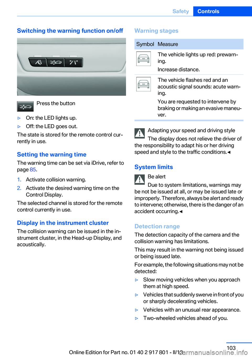
Switching the warning function on/off
Press the button
▷On: the LED lights up.▷Off: the LED goes out.
The state is stored for the remote control cur‐
rently in use.
Setting the warning time
The warning time can be set via iDrive, refer to
page 85.
1.Activate collision warning.2.Activate the desired warning time on the
Control Display.
The selected channel is stored for the remote
control currently in use.
Display in the instrument cluster
The collision warning can be issued in the in‐
strument cluster, in the Head-up Display, and
acoustically.
Warning stagesSymbolMeasureThe vehicle lights up red: prewarn‐
ing.
Increase distance.The vehicle flashes red and an
acoustic signal sounds: acute warn‐
ing.
You are requested to intervene by
braking or making an evasive maneu‐
ver.
Adapting your speed and driving style
The display does not relieve the driver of
the responsibility to adapt his or her driving
speed and style to the traffic conditions.◀
System limits Be alert
Due to system limitations, warnings may
be not be issued at all, or may be issued late or
improperly. Therefore, always be alert and ready
to intervene; otherwise, there is the danger of an
accident occurring.◀
Detection range
The detection capacity of the camera and the
collision warning has limitations.
This may result in the warning not being issued
or being issued late.
For example, the following situations may not be
detected:
▷Slow moving vehicles when you approach
them at high speed.▷Vehicles that suddenly swerve in front of you
or sharply decelerating vehicles.▷Vehicles with an unusual rear appearance.▷Two-wheeled vehicles ahead of you.Seite 103SafetyControls103
Online Edition for Part no. 01 40 2 917 801 - II/13
Page 105 of 242
Camera
The camera is located near the base of the mir‐
ror.
Keep the windshield in the area behind the in‐
terior rear view mirror clean and clear.
Switching on/off Press the button
▷On: the LED lights up.▷Off: the LED goes out.
The state is stored for the remote control cur‐
rently in use.
Display in the instrument cluster
▷Lines: system is activated.▷Arrows: at least one lane marking
was detected and warnings can be
issued.
Issued warning
If you leave the lane and if a lane marking has
been detected, the steering wheel begins vi‐
brating.
If the turn signal is set before changing the lane,
a warning is not issued.
End of warning
The warning ends:
▷Automatically after approx. 3 seconds.▷When returning to your own lane.▷When braking hard.▷When using the turn signal.
System limits
The system may not be fully functional in the
following situations:
▷In heavy fog, rain or snowfall.▷In the event of worn, poorly visible, merging,
diverging, or multiple lane markings such as
in construction areas.▷When lane markings are covered in snow,
ice, dirt or water.▷In tight curves or on narrow lanes.▷When the lane markings are covered by ob‐
jects.▷When driving very close to the vehicle in
front of you.▷When driving toward bright lights.▷When the windshield behind the interior
rearview mirror is fogged over, dirty or cov‐
ered with stickers, etc.▷During calibration of the camera immedi‐
ately after vehicle shipment.
Active Blind Spot Detection
The concept
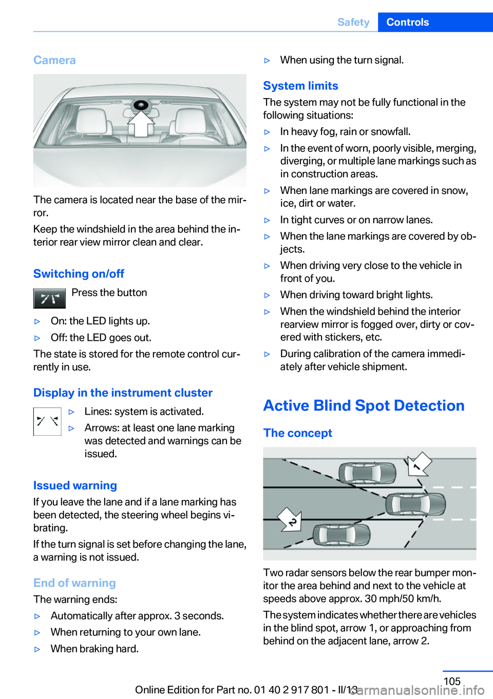
Two radar sensors below the rear bumper mon‐
itor the area behind and next to the vehicle at
speeds above approx. 30 mph/50 km/h.
The system indicates whether there are vehicles
in the blind spot, arrow 1, or approaching from
behind on the adjacent lane, arrow 2.
Seite 105SafetyControls105
Online Edition for Part no. 01 40 2 917 801 - II/13
Page 111 of 242
Indicator/warning lamps
When DSC is deactivated, DSC OFF is dis‐
played in the instrument cluster.
The indicator lamp lights up: DSC is de‐
activated.
DTC Dynamic Traction
Control
The concept
The DTC system is a version of the DSC in which
forward momentum is optimized.
The system ensures maximum forward momen‐
tum on special road conditions, e.g., unplowed
snowy roads, but driving stability is limited.
It is therefore necessary to drive with appropri‐
ate caution.
You may find it useful to briefly activate DTC un‐
der the following special circumstances:▷When driving in slush or on uncleared,
snow-covered roads.▷When rocking the vehicle or driving off in
deep snow or on loose surfaces.▷When driving with snow chains.
Deactivating/activating DTC Dynamic
Traction Control
Activating the Dynamic Traction Control DTC
provides maximum traction on loose ground.
Driving stability is limited during acceleration
and when driving in bends.
Activating DTC Press the button.
TRACTION is displayed in the instru‐
ment cluster and the indicator lamp for DSC
OFF lights up.
Deactivating DTC
Press the button again.
TRACTION and the DSC OFF indicator
lamp go out.
xDrive
xDrive is the all-wheel-drive system of your ve‐
hicle. Concerted action by the xDrive and DSC
further optimize traction and driving dynamics.
The xDrive all-wheel-drive system variably dis‐
tributes the drive forces to the front and rear
axles as demanded by the driving situation and
road surface.
Dynamic Damping Control
The concept
This system reduces undesirable vehicle mo‐
tion when using a dynamic driving style or trav‐
eling on uneven road surfaces.
The system enhances driving dynamics and
comfort as required for the road surface and
driving style.
Programs
The system offers several different programs.
The programs can be selected via the Driving
Dynamics Control, refer to page 112.
SPORT
Consistently sporty control of the shock absorb‐
ers for greater driving agility.
SPORT+
Consistently sporty control of the shock absorb‐
ers and engine controller for greater driving agil‐
ity when driving with limited driving stabilization.
COMFORT / ECO PRO
Balanced control of the vehicle.Seite 111Driving stability control systemsControls111
Online Edition for Part no. 01 40 2 917 801 - II/13