2013 BMW 135IS CONVERTIBLE ignition
[x] Cancel search: ignitionPage 81 of 284
80
ControlsControls overview
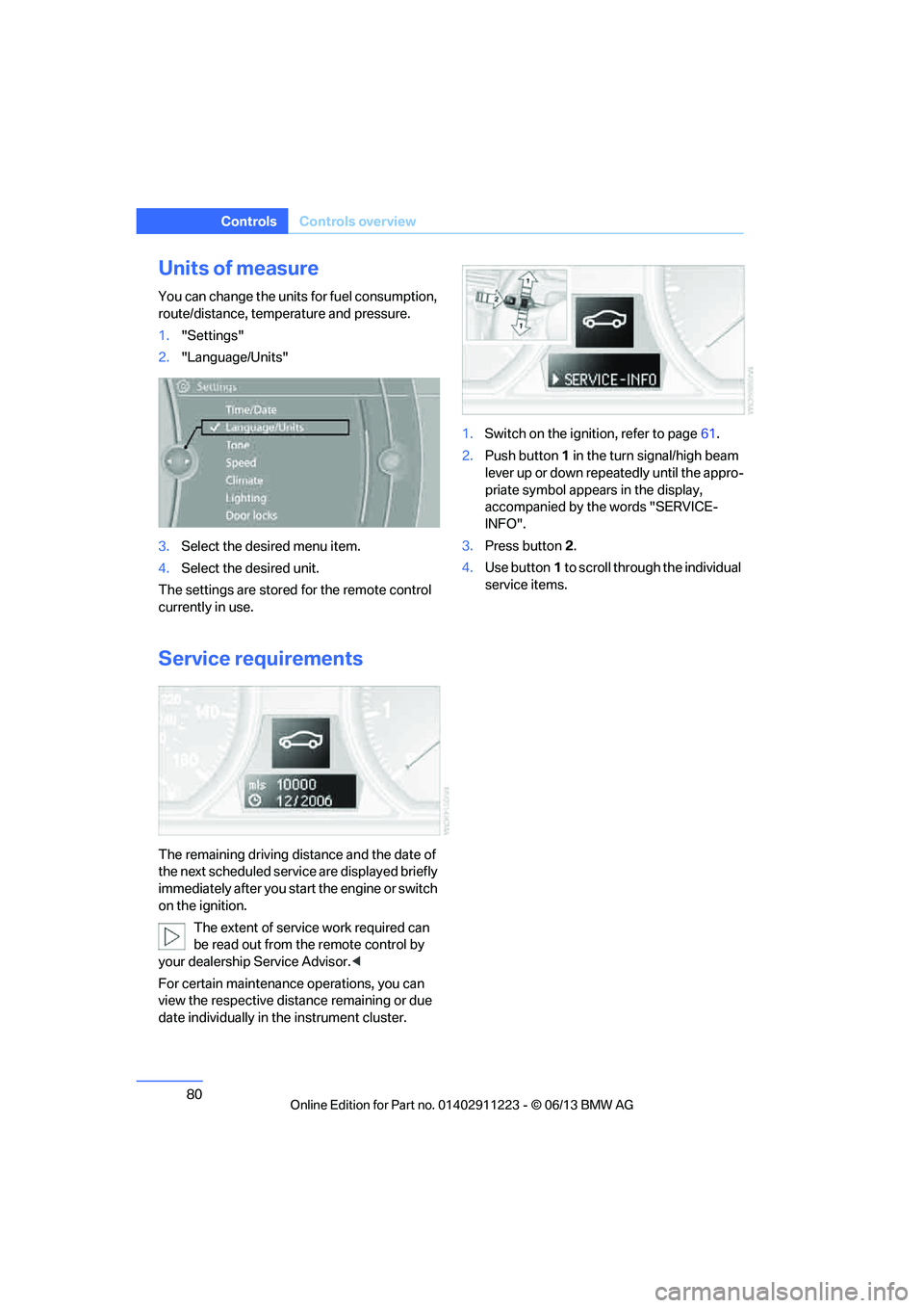
Units of measure
You can change the units for fuel consumption,
route/distance, temperature and pressure.
1."Settings"
2. "Language/Units"
3. Select the desired menu item.
4. Select the desired unit.
The settings are stored for the remote control
currently in use.
Service requirements
The remaining driving distance and the date of
the next scheduled servic e are displayed briefly
immediately after you start the engine or switch
on the ignition.
The extent of service work required can
be read out from the remote control by
your dealership Service Advisor. <
For certain maintenance operations, you can
view the respective distance remaining or due
date individually in the instrument cluster. 1.
Switch on the ignition, refer to page 61.
2. Push button 1 in the turn signal/high beam
lever up or down repe atedly until the appro-
priate symbol appear s in the display,
accompanied by the words "SERVICE-
INFO".
3. Press button 2.
4. Use button 1 to scroll through the individual
service items.
00320051004F004C00510048000300280047004C0057004C005200510003
Page 85 of 284
84
ControlsControls overview
Date
The settings are stored for the remote control
currently in use, refer also to Personal Profile on
page32.
Setting the date
In the instrument cluster
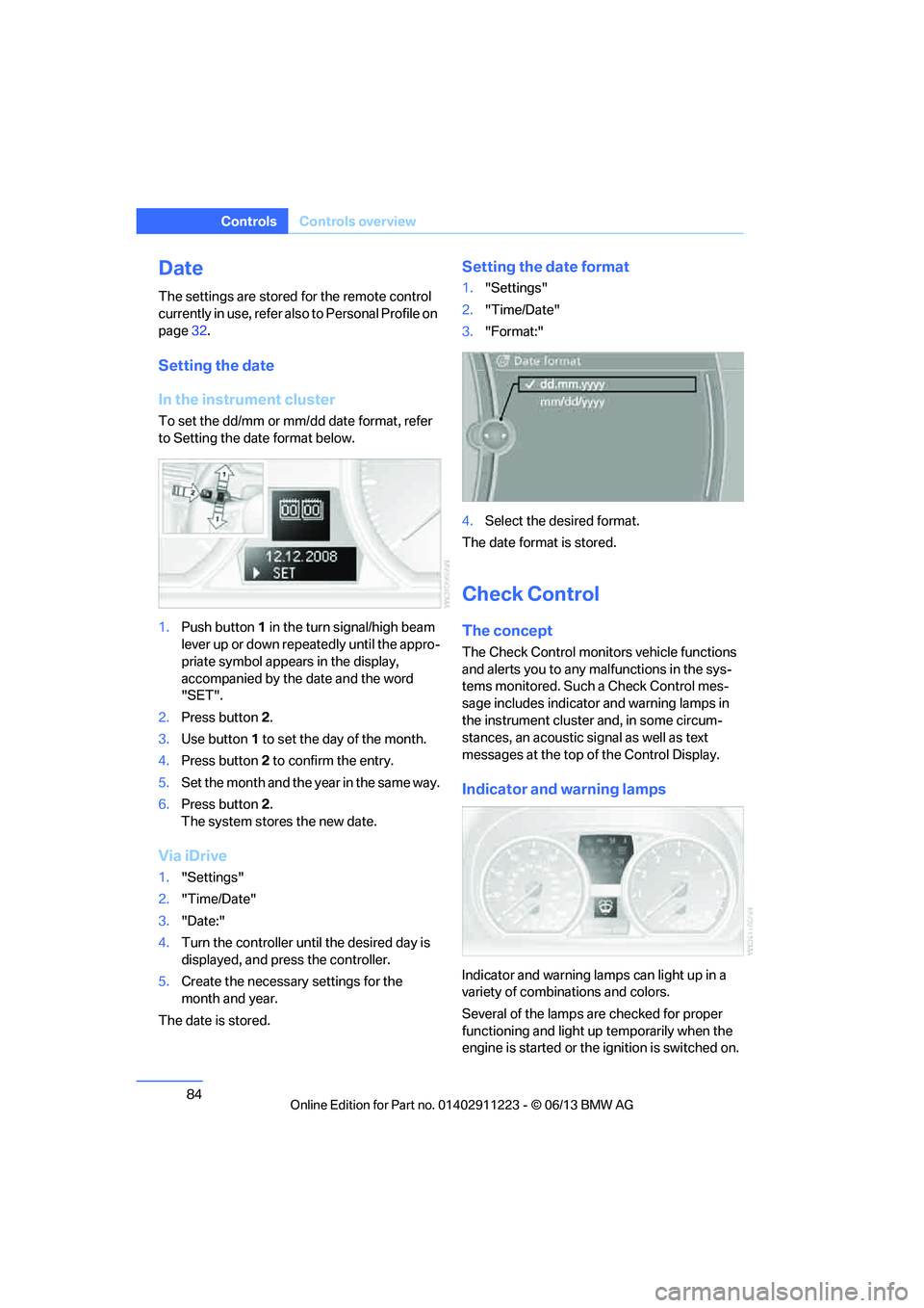
To set the dd/mm or mm/dd date format, refer
to Setting the date format below.
1. Push button 1 in the turn signal/high beam
lever up or down repe atedly until the appro-
priate symbol appear s in the display,
accompanied by the date and the word
"SET".
2. Press button 2.
3. Use button 1 to set the day of the month.
4. Press button 2 to confirm the entry.
5. Set the month and the ye a r i n t he s a m e w a y .
6. Press button 2.
The system stores the new date.
Via iDrive
1. "Settings"
2. "Time/Date"
3. "Date:"
4. Turn the controller until the desired day is
displayed, and press the controller.
5. Create the necessary settings for the
month and year.
The date is stored.
Setting the date format
1. "Settings"
2. "Time/Date"
3. "Format:"
4. Select the desired format.
The date format is stored.
Check Control
The concept
The Check Control monitors vehicle functions
and alerts you to any malfunctions in the sys-
tems monitored. Such a Check Control mes-
sage includes indicato r and warning lamps in
the instrument cluster and, in some circum-
stances, an acoustic signal as well as text
messages at the top of the Control Display.
Indicator and warning lamps
Indicator and warning lamps can light up in a
variety of combinations and colors.
Several of the lamps are checked for proper
functioning and light up temporarily when the
engine is started or the ignition is switched on.
00320051004F004C00510048000300280047004C0057004C005200510003
Page 89 of 284

88
ControlsTechnology for driving comfort and safety
Technology for driving comfort and safety
Vehicle equipment
In this chapter, all pr oduction, country, and
optional equipment that is offered in the model
range is described. For this reason, descrip-
tions will be given of some equipment that may
not be available in a vehi cle, for example due to
the special options or national-market version
selected. This also app lies to safety related
functions and systems.
Park Distance Control PDC
The concept
The PDC assists you with maneuvering in tight
parking spaces. Acoustic signals and a visual
indicator warn you of the presence of an object
behind your vehicle. Four ultrasonic sensors in
the bumper measure the distance.
These sensors have a range of approx. 6.5 ft/
2 m. However, an acoustic warning does not
sound until an object is approx. 24 in/60 cm
from the corner sensors or approx. 5 ft/1.50 m
from the center sensors.
PDC is a parking aid that can indicate
objects when they are approached
slowly, as is usually th e case when parking.
Avoid approaching an object at high speed; oth-
erwise, physical circumstances may lead to the
system warning being issued too late. <
Switching on automatically
With the engine running or the ignition switched
on, the system is activated after approx. second
when you engage reverse gear or move the
automatic transmission selector lever to
position R. Wait this short period before driving.
Switching off automatically
After approx. 164 ft/50 m of driving or above
approx. 18 mph/30 km/h, the system switches
off and the LED goes out.
Signal tones
When nearing an object, its position is indicated
correspondingly by an in terval tone. As the dis-
tance between vehicle an d object decreases,
the intervals betwee n the tones become
shorter. If the distance to the nearest object
falls to below roughly 1 ft/30 cm, then a contin-
uous tone sounds.
An interval tone is interrupted after approx.
3seconds:
> If you stop in front of an object that has been
detected by only one of the corner sensors
> If you are driving parallel to a wall
Malfunction
The warning lamp lights up. A mes-
sage appears on the Control Display.
PDC is malfunctioning. Have the
system checked.
To avoid this problem, keep the sensors clean
and free of ice or snow in order to ensure that
they will continue to op erate effectively. When
using a high-pressure cleaner, do not spray the
sensors for extended periods of time and only
from a distance of at least 1 ft/30 cm.
PDC with visual warning
The approach of the vehicle to an object is
shown on the Control Display. Objects that are
farther away are displayed on the Control Dis-
play before a signal tone sounds. The display
appears on the Control Display as soon as PDC
is activated.
00320051004F004C00510048000300280047004C0057004C005200510003
Page 101 of 284

100
ControlsLamps
Lamps
Vehicle equipment
In this chapter, all pr oduction, country, and
optional equipment that is offered in the model
range is described. For this reason, descrip-
tions will be given of some equipment that may
not be available in a vehi cle, for example due to
the special options or national-market version
selected. This also app lies to safety related
functions and systems.
Overview
0 Lamps off,
daytime running lights
1 Parking lamps and daytime running lights
2 Low beams,
welcome lamps
3 Automatic headlamp control, daytime run-
ning lights, welcome lamps, High-beam
Assistant, Adaptive Light Control
Parking lamps/low beams,
automatic headlamp control
General information
When the driver's door is opened with ignition
switched off, then the exterior lighting is auto-
matically switched off if the light switch is in
position 0, 2 , or 3.
Parking lamps
In switch position 1, the front, rear and side
vehicle lighting is switch ed on. You can use the
parking lamps for parking.
With halogen headlamps: when the ignition is
switched off and the sw itch is in position 1, only
the outside sections of the rear lamps are illumi-
nated, refer to page 246.
The parking lamps will discharge the bat-
tery. Therefore, do not leave them on for
unduly long periods of time; otherwise, the bat-
tery might not have enou gh power to start the
engine. It is preferable to switch on the left-
hand or right-hand roadside parking lamps,
refer to page 102.<
Low-beam headlamps
The low beams light up wh en the light switch is
in position 2 and the ignition is on.
Automatic headlamp control
When the switch is in position 3, the low beams
are switched on and off automatically depend-
ing on ambient lighting conditions, e.g. in a tun-
nel, in twilight, or if there is precipitation. The
Adaptive Light Control is active. The LED next
to the symbol is illu minated when the low
beams are on. You can also activate the daytime
running lights, refer to page 101. In the situa-
tions described above, the lamps then automat-
ically switch from daytime running lights to low
beams.
The headlamps may also come on when the
sun is sitting low on a blue sky.
The low beams remain switched on inde-
pendent of the ambient lighting condi-
tions when you switch on the fog lamps. <
The automatic headlamp control cannot
serve as a substitute for your personal
judgment in determining when the lamps
should be switched on in response to ambient
00320051004F004C00510048000300280047004C0057004C005200510003
Page 102 of 284
101
Lamps
Controls
lighting conditions. For example, the system
cannot detect fog or hazy weather. To avoid
safety risks, you should always switch on the
low-beam headlamps ma
nually under these
conditions.<
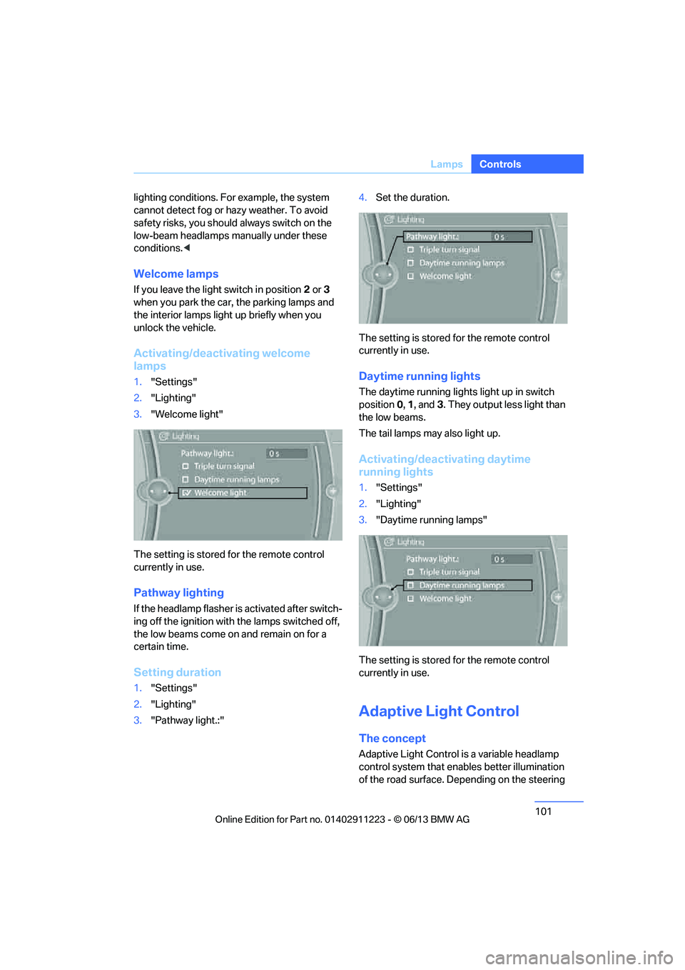
Welcome lamps
If you leave the light switch in position 2 or 3
when you park the car, the parking lamps and
the interior lamps light up briefly when you
unlock the vehicle.
Activating/deactivating welcome
lamps
1. "Settings"
2. "Lighting"
3. "Welcome light"
The setting is stored for the remote control
currently in use.
Pathway lighting
If the headlamp flasher is activated after switch-
ing off the ignition with the lamps switched off,
the low beams come on and remain on for a
certain time.
Setting duration
1. "Settings"
2. "Lighting"
3. "Pathway light.:" 4.
Set the duration.
The setting is stored for the remote control
currently in use.
Daytime running lights
The daytime running light s light up in switch
position 0, 1 , and 3. They output less light than
the low beams.
The tail lamps may also light up.
Activating/deactivating daytime
running lights
1. "Settings"
2. "Lighting"
3. "Daytime running lamps"
The setting is stored for the remote control
currently in use.
Adaptive Light Control
The concept
Adaptive Light Control is a variable headlamp
control system that enables better illumination
of the road surface. Depending on the steering
00320051004F004C00510048000300280047004C0057004C005200510003
Page 103 of 284

102
ControlsLamps
angle and other parameters, the light from the
headlamp follows the course of the road.
In tight curves such as on switchbacks or when
turning, at speeds up to approx. 40 mph/
70 km/h, an additional, cornering light is
switched on that lights up the area inside the
curve.
Activating Adaptive Light Control
With the ignition switched on, turn the light
switch to position 3, refer to page 100.
The corner-illuminating lamp is switched on
automatically, depending on the steering wheel
angle or turn signal indicator.
Standstill function: to avoid blinding oncoming
traffic, the Adaptive Light Control does not
direct light toward the driver's side when the
vehicle is at a standstill.
When you are reversing, only the corner-illumi-
nating lamps are switched on and active on
both sides.
Malfunction
The warning lamp lights up. A mes-
sage appears on the Control Display.
The Adaptive Light Control is mal-
functioning or failed. Ha ve the system checked
as soon as possible.
High beams/roadside parking
lamps
1 High beams
2 Headlamp flasher
3 Roadside parking lamps
Roadside parking lamps, left or right
There is an additional option of switching on the
lamps on the side of the car facing the road
when parked.
Switching on
After parking the vehicle, press the lever up or
down beyond the pressu re point for approx.
1 second, arrow 3.
The roadside parking lamps drain the bat-
tery. Therefore, do not leave them on for
unduly long periods of time; otherwise, the bat-
tery might not have enou gh power to start the
engine. <
Switching off
Press the lever in the o pposite direction to the
pressure point, arrow 3.
High-beam Assistant
The concept
This system automatically switches the high
beams on and off. The procedure is controlled
by a sensor on the front of the interior rearview
mirror. The assistant ensures that the high
beams are switched on whenever the traffic sit-
uation allows. It handle s this task for you and
gives you the benefit of the best possible view.
You can intervene at any time and switch the
high beams on and off as usual.
Activating the system
1. Turn the light switch to position 3, refer to
page 100.
2. With the low beams switched on, briefly
push the turn signal/high beam lever in the
direction of the high beam.
The indicator lamp in the instrument
cluster lights up when the high beams
are activated. The system automati-
cally switches from hi gh beams to low beams
00320051004F004C00510048000300280047004C0057004C005200510003
Page 112 of 284
111
Practical interior accessories
Controls
Practical interior accessories
Vehicle equipment
In this chapter, all production, country, and
optional equipment that is offered in the model
range is described. For this reason, descrip-
tions will be given of some equipment that may
not be available in a vehi
cle, for example due to
the special options or national-market version
selected. This also app lies to safety related
functions and systems.
Integrated universal remote
control
The concept
The Integrated universal remote control can be
used to operate up to 3 functions of remote-
controlled devices such as garage door open-
ers or lighting systems. The Integrated univer-
sal remote control thus replaces as many as
three different hand-held transmitters. To oper-
ate them, the buttons on the interior rearview
mirror must be programmed with the desired
functions. Programming requires the hand-held
transmitter for the respective device.
To prevent possible damage or injury,
before programming or using the inte-
grated universal remote control to operate a
device, always inspect the immediate area to
make certain that no people, animals or objects
are within the pivoting or travel range of the
device being operated.
Also follow the safety in structions supplied with
the hand-held transmitter. <
For security reasons, make sure to delete the
stored functions before selling the vehicle, refer
to page 113.
Compatibility
If this symbol appears on the package
or in the instructions supplied with the
device to be operated, you can gener-
ally assume that the devi ce is compatible with
the Integrated univer sal remote control.
For additional questions, please consult:
> Your BMW center.
> www.homelink.com on the Internet.
HomeLink is a registered trademark of Johnson
Controls, Inc.
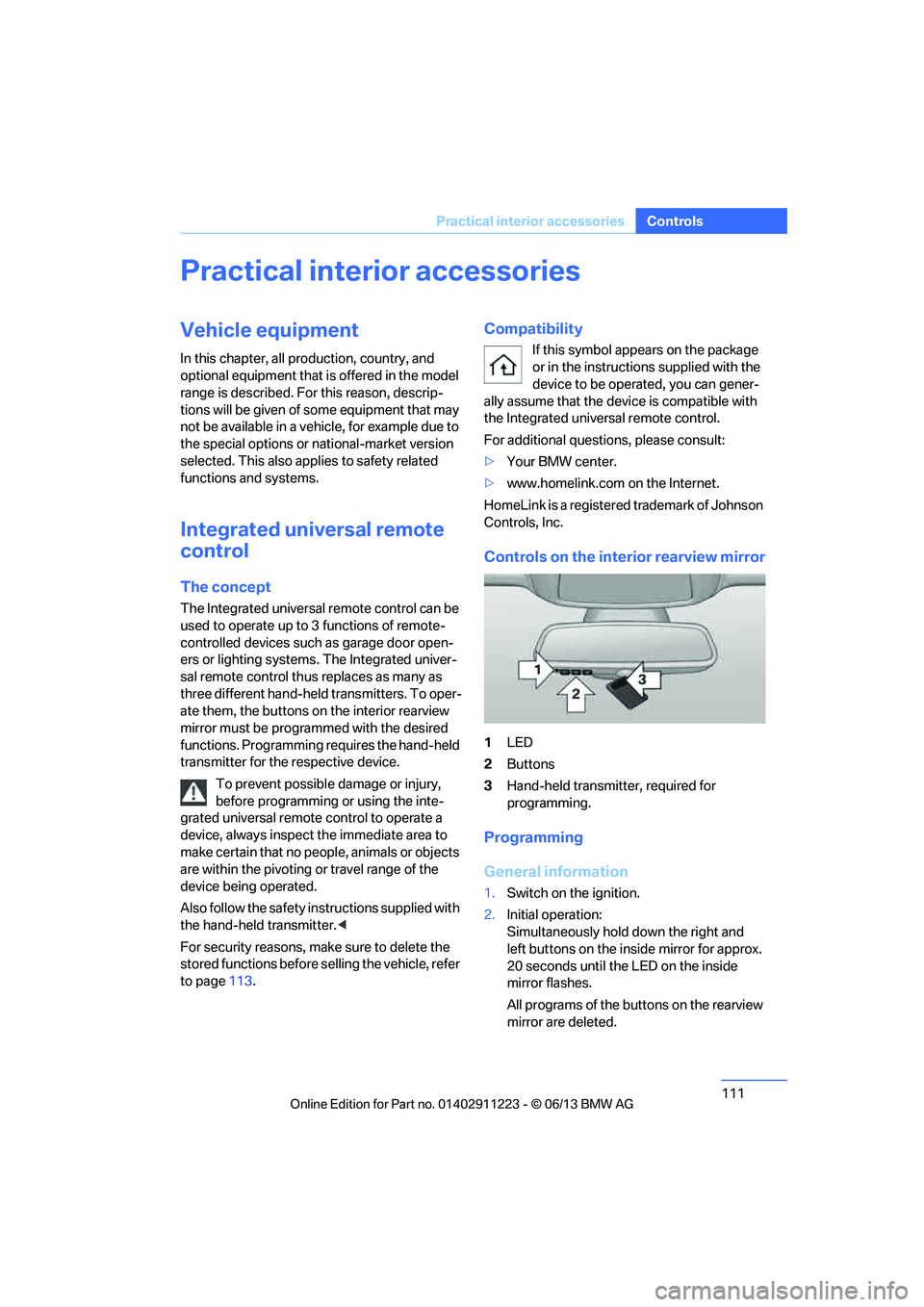
Controls on the inte rior rearview mirror
1LED
2 Buttons
3 Hand-held transmitter, required for
programming.
Programming
General information
1.Switch on the ignition.
2. Initial operation:
Simultaneously hold down the right and
left buttons on the inside mirror for approx.
20 seconds until the LED on the inside
mirror flashes.
All programs of the bu ttons on the rearview
mirror are deleted.
00320051004F004C00510048000300280047004C0057004C005200510003
Page 113 of 284
112
ControlsPractical interior accessories
3.Hold the hand-held transmitter of the
device to be controlled about 1 in/2.5 cm to
3 in/8 cm away from the buttons on the
inside mirror.
The required distance depends on the
hand-held transmitter.
4. Simultaneously press and hold the button
of the desired function on the hand-held
transmitter and the button to be pro-
grammed on the inside mirror.
The LED on the inside mirror will flash
slowly at first.
5. As soon as the LED flashes rapidly, release
both buttons. The rapi d flashing indicates
that the button on th e inside mirror has
been programmed.
If the LED does not flash rapidly within
60 seconds, change the distance between
the inside mirror and the hand-held trans-
mitter and repeat this step. This may
require several attempts. Allow at least
15 seconds between attempts.
6. To program additional functions on the
other buttons of the inside mirror, repeat
steps 3 through 5.
The buttons on the inside mirror can be used to
operate the devices if th e ignition is switched
on.
Special procedure with alternating-
code systems
If the device fails to function even after repeated
programming, check whether the device to be
controlled uses an alternating-code system.
To do so, either read the instructions for the
device or hold down the programmed button on
the inside mirror. If the LED on the inside mirror
flashes quickly at first and then remains lit for
2 seconds, the device uses an alternating-code
system. The LED flashes and lights up repeat-
edly for approx. 20 seconds.
In devices with an alternating-code system, the
Integrated universal remote control and the
device must also be synchronized. For information about synchronizing can also
be found in the operating instructions for the
device to be set.
Programming will be easier with the aid of a
second person.
Synchronizing:
1.
Park your vehicle within the range of the
remote-controlled device.
2. Program the Integrated universal remote
control as described above.
3. Locate and press the synchronization
button on the device to be set. You have
approx. 30 seconds to perform the next
step.
4. Hold down the prog rammed button on the
inside mirror for approx. 3 seconds and then
release it. Repeat this operation, up to three
times if necessary, to complete the syn-
chronization. If the synchronization has
succeeded, the programmed function is
performed.
Reprogramming individual buttons
1. Switch on the ignition.
2. Hold the hand-held transmitter of the
device to be controlled about 1 in/2.5 cm to
3 in/8 cm away from the buttons on the
inside mirror.
The required distance depends on the
hand-held transmitter.
3. Press the desired button on the inside
mirror.
4. If the LED on the inside mirror flashes
slowly after approx. 20 seconds, press the
transmit key of the hand-held transmitter.
5. As soon as the LED flashes rapidly, release
both buttons.
If the LED does not flash rapidly after
approx. 60 seconds, alter the distance and
repeat the step.
00320051004F004C00510048000300280047004C0057004C005200510003