2013 AUDI A4 SEDAN instrument cluster
[x] Cancel search: instrument clusterPage 28 of 294

26 Driver in formation d isplay
¢fig . 10 . The data from the single -trip mem
ory (memory leve l 1) is being displayed if a
D
appears in the display . If a II is shown, then
the data from the total -trip memory is being
d isplayed (memory leve l 2). The fuel pump
nozzle
iii indicates the efficiency program*
¢ page 27.
Single-tr ip m emory (Trip computer 1 )
The single-trip memory stores the trip infor
mat ion from the time the ignition is turned o n
until it is turned off. If the trip is continued
w ithin 2 hours from the t ime the ignition was
turned off, the new data will be included in
the calcu lation of the current trip i nfo rma
tion .
If the t rip is inte rrupted fo r more than 2
hours the memory is reset automati ca lly.
Total -trip memory (Trip computer 2)
Unlike the sing le-trip memory, the tota l- tr ip
memory is not reset automatically . Th is per
mits you to evaluate your d riving data for the
enti re pe riod be tween manual rese ts.
Efficiency program*
The effic iency program can help you to use
less fuel ¢
page 2 7.
Operation
App lies to vehicles: with trip computer
The trip computer is controlled by two
switches on the windshield wiper lever .
Fig. 11 W indsh ie ld wipe r leve r: co ntrols for the tri p
co mpute r
M
"' 0 N
"' co a:,
~ To d isp lay the trip computer memory levels ,
press the
I RES ET I button @¢ fig. 11 re
peatedly unt il the desired memory leve l is
shown in the d isplay .
~ To display tr ip in format ion wit hin a memory
level, press the top or bottom part of the
function se lection switch @.
T he trip computer will not ope rate un less the
ignition is on. W hen you t urn on the ignition,
the function that was in use when you last
turned the ignition off will be displayed .
In add ition to info rmation on the trip comput
er (trip computer 1 and 2 and the efficiency
program *), t he digital spee dometer and infor
mation regard ing the nav igat ion system* can
also be displayed. To switch the d isp lay be
tween the different information, tap the
I RESET ! button@ briefly.
Sett ing values to zero
To de lete one current va lue from the trip com
puter, se lect the des ired funct ion and press
t h e
I RES ET I button @for at least one second.
The following values can be set to zero
indi
vidually :
- Average fue l mi leage
- Average speed
- Elapsed t ime
- Dis tance
All cur rently d isplayed va lues are deleted in
the eff iciency program*.
In add it ion,
all the values in the single-trip or
the total-tr ip memory can be de leted simulta
neously ¢
page 26.
(D Tips
All stored va lues w ill be lost if the veh icle
battery is discon nected .
Basic Settings for the trip computer
Applies to vehicles: with trip computer
The radio or MMI* operating unit is used for
setting the trip computer's basic settings.
~ Select: Function b utton ICAR ! > Instrument
cluster > On -board computer 1 or On-board
computer 2 . .,.
Page 29 of 294

The values in the single-t rip or the total-trip
memory can a ll be reset to zero at the same
time under
Reset in the menu .
I n addition, you can determine what informa
tion from the trip computer should be shown
in the instrument cluster display. If one of the
p ieces of driver information is turned
Off , that
driver information w ill not be shown in the
display. The information will continue to be
calculated by the trip computer and can be
turned back
On at any t ime.
(D Tips
- This function is not avai lab le on all
vehicles.
- The driving information in the efficiency
program is also reset to zero with the
s ingle-trip memory.
Gearshift Indicator
A ppl ies to vehicles: with manu al transmi ssion a nd gea r·
shi ft indica tor
This indicator con help conserve fuel.
~~~------------~~ ~.;;-
Fig. 12 Display: Gea rs hi ft indicator
The radio or MMI* can be used to activate or
deactivate the gearsh ift indicator.
Driving information -fading in and out
.,. Se lect: ICARlfunction button> Instrument
cluster
> Shifting recommendation . Or
m ~ ~ a, a,
.,. Select: ICARI funct ion button> Car systems
control button > Driver assist > Gear recom
mendation .
In order to become familiar with the gearshift
indictor, at first just drive the way you are
used to.
If the current gear -and the driving
situation -is not th e best one for conserving
Driver information display 2 7
fuel, then the indicator wi ll display the recom
mended gear. The display shows the current
gear and the gear that is recommended
¢fig. 12.
-Upshifting The disp lay wi ll light up to the
right of the gear currently selected if it is
recommend ing a higher gear .
-Downshifting: The display wi ll lig ht up to
the
left of the gear currently se lected if it is
recommending a lower gear .
Sometimes the indicator will recommend
skipping a gear (3
> 5).
If there is no gearshift recommendation, then
just drive in the appropriate gear for conserv
ing fuel.
(D Note
This indicator can help you conserve fuel.
This indicator is not meant to show you
which gear you sho uld always be in in all
driving situations . Sometimes, in situa
tions s uch as passing, dr iv ing through
mountains or when towing a trailer, there
won't be any gearshift recommendation.
(D Tips
The display does not light up when the
clutch pedal is be ing depressed.
Efficiency program
Description
App lies t o vehicles: wi th trip co mp ute r wi th effici ency
prog ram
Fig. 13 D isplay: efficie ncy progra m
Page 32 of 294
30 Driver information display
the approp riate service on your vehicle. You
a lso have the possibility to reset the oil
change schedule after having performed an
oil change according to Audi specifications.
Select
I CAR I function button > Service interval
display > Reset oil change interval
or ICARI
function button> Car systems control button
> Servicing & checks > Reset oil change inter
val.
(CT;) Note
If you disconnect the battery terminals, no
calculations can be made for the service
interva l display during this time and no
service reminder will appear. Remember
that observing the proper serv ice interva ls
is vitally important to extending the life of
your vehicle, particularly the engine, and
maintaining its value. Even if the mileage
driven is low, the maximum period of one
year from one serv ice to the next must not
be exceeded.
@ Tips
-Do not reset the display between oil
changes, otherw ise the display will be in
correct.
- The information in the Service Reminder
remains stored even when the vehicle
battery is disconnected.
On-Board Diagnostic
system (OBD)
Malfunction Indicator Lamp (MIL)
The Malfunction Indicator Lamp (MIL) II in
the instrument cluster is part of the On-Board
Diagnostic (OBD II) system.
The warning/indicator light illuminates when
the ignition is switched on and goes out after
the engine starts and the idle has stabi lized .
This indicates that the MIL is working proper
l y.
If the light does not go out after the engine
is started, or illuminates while you are driv
ing, a malfunction may exist in the engine sys- tern.
If the
light illuminates, the catalytic con
verter could be damaged.
Continue driving
with reduced power (avoid
ing sustained high speeds and/or rapid accel
erations) and have the condition corrected.
Contact your authorized Audi dea ler.
If the light illuminates, the electronic speed
limiter may also be malfunct ioning. For more
information
q page 31, El ectronic speed
limiter .
An improperly closed fuel filler cap may also
cause the MIL light to illuminate
~page 212.
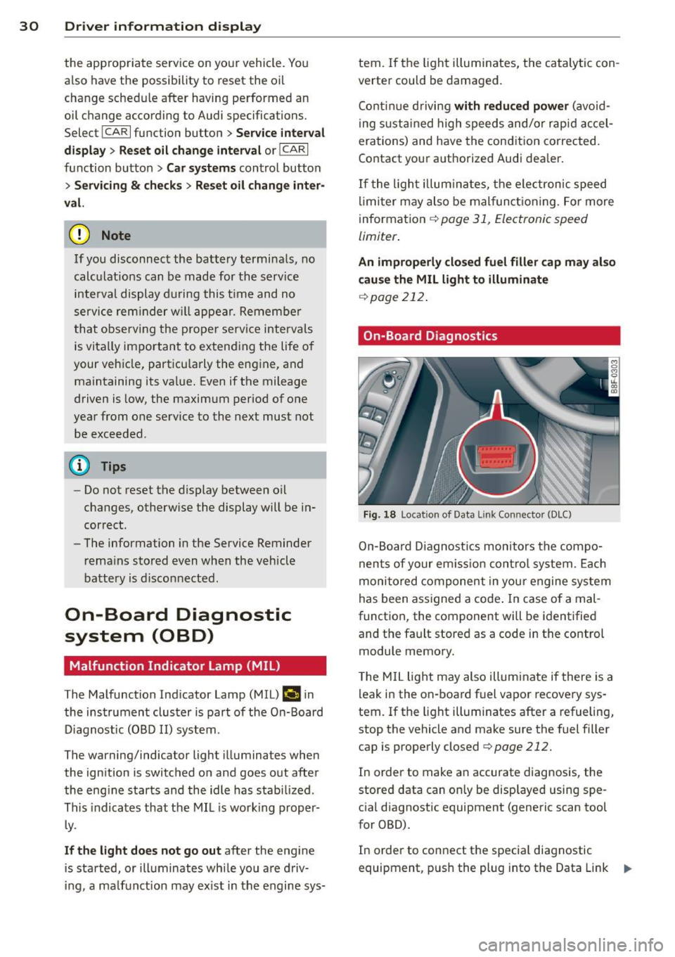
On-Board Diagnostics
Fig. 18 Locat ion of Data L ink Connector (DLC)
On-Board Diagnostics monitors the compo
nents of your em ission control system . Each
monitored component in your engine system
has been assigned a code . In case o f a mal
function, the component will be identified
and the fault stored as a code in the control
module memory.
T he MIL light may also illuminate if there is a
leak in the on-board fuel vapor recovery sys
tem.
If the light illuminates after a refueling,
stop the vehicle and make sure the fuel filler
cap is properly closed
q page 212.
In order to make an accurate diagnosis, the
stored data can on ly be displayed using spe
cial diagnostic equipment (generic scan tool
for OBD).
In order to connect the special diagnostic
equipment, push the plug into the Data Link ..,.
Page 45 of 294

Valet parking
Applies to vehicles: with folding a nd lockable rear seat
backs
The valet parking feature protects the lug
gage comportment from unauthorized ac
cess.
Fig. 35 Glove compa rtm en t: val et parking button
You can switch the "valet park ing function" on
when someone else is parking your vehicle .
When the function is switched on, the vehicle
can be dr iven, locked and unlocked us ing the
maste r key, but access to the luggage com
partment is not permitted .
• Take the mechanical key out of the master
key
c::> page 34 .
• Open the glove compartment c::> page 61 .
• Activate c::> fig . 35 the "valet parking " fea
tu re by p ress ing the
!VALET ! button. The in
dicator light in the switch i lluminates.
• Close the glove compartment and lock it
with the mechanical key.
• Lock both rear seatbacks with the mechani
cal key
c::> page 64.
• Lock the luggage compartment pass
through with the mechanical key
c::>poge 66.
• Leave the master key with the service per
sonnel for parking and keep the mechanica l
key with you.
The fol low ing buttons are deac tivated when
the valet parking function is sw itched on:
-I a I button in the dr iver's door
-la l button on the master key
- Handle in the rear lid
When the valet parking feature is activated,
the message
Valet parking activated appears
Opening and closing 43
in the instrument cluster display when you
switch the ignition on.
Page 47 of 294

(D Tips
-The light sensor * for headl ight control is
l ocated in the rear view m irror mount.
You should therefore not apply any st ick
ers to the windsh ield in this area in order
to prevent malfunctions or failures .
- Some exterior lighting functions can be
adjusted
¢ page 45.
-When yo u remove you r key from the igni
tion w hile the vehicle's lights are turned
on, a buzzer sounds as long as the driv
er's door is open.
- In cool or damp weather, t he ins ide of
the headlights, turn signa ls and tail
li ghts can fog ove r due to the tem pera
ture diffe ren ce betw een the inside and
outside. They will clear shor tly after
swi tching t hem on. This d oes not aff ect
the service life of the ligh ting.
- In the even t of a ligh t sensor malfunc
tion, the drive r is no tifie d in the inst ru
ment cluster disp lay ~
page 2 2.
Turn signals and high beam lever
The lever operates the turn signal s, the high
beams and the headlight flasher .
Fig. 37 Turn sig na l and high beam leve r
Turn signals ¢i ¢
The turn s ignals activate when you move the
l ever into a turn s ignal position when the ign i
tion is sw itched on.
(D -right turn signal
@ -Left turn signa l
The turn s ignal b links three times if you just
tap the lever . Clear
vi
sion 45
High beams and headlight flasher @:D
Move the lever to the corresponding posit io n:
@ -high beams on
@-high beams off or headlight flasher
T he ind icator light
II in the instr ument clus
ter turns on .
Notes on these features
-The turn signals on ly wor k w it h t he ignition
t urned on. The indica tor l igh ts
11 or II in
the instrument cluste r also blink .
- Aft er you have tu rned a corner, the turn s ig
na l swi tches off au tom atically .
- The
high beam wo rks only when the head
lights a re on. The indicator Ligh t. in the
instrumen t clus ter illuminates when the
high beams are on .
- The
headligh t flasher works on ly as long as
you ho ld the lever -even if the re are no
lights switched o n. The ind icator light
Ill i n
the inst rument cluster illuminates when you
use the headlight flasher.
&_ WARNING
Do not use the h igh beam or head light
flasher if you kn ow that these could b lind
oncom ing traffic.
Adjusting exterior lighting
The functions are selected in the radio or
MM!* .
.. Select: I CAR ! function b utton > Exter io r
light ing .
Or
.. Select: I CAR I function button > Car Systems
cont ro l butto n > Vehicle settings > Exterior
lighting .
Coming home (light when leav ing car )*,
Leaving home (light when unlocking car)*
The coming home function illumi nates the
area around the vehicle when the ignition is
switched off and the drive r's door is open ed.
Depend ing on ve hicle equipment, t he fu nction
can be sw itched on and off or the length of
time the lights rem ain on* can be ad justed . .._
Page 80 of 294

78 On the road
Emerg ency b rake function
An emergency brake ensures t hat the vehicle
can be slowed down even if the
normal brakes
fail c::>
page 79, Emergency broking.
Indicat or light s
-If the par king b rake is closed w ith the igni
t ion
s witc hed on the . (USA models) /
• (Canada mode ls) indica tor lights come
on in the instrum ent cluster and the switch .
-If the parking brake is closed w ith the igni
tion
s witc hed off the . (USA models) /
• (Canada mode ls) indicator lights come
on in the instrument clust er and th e switch
for about 20 seconds .
A WARNING
If a gear or a drive range (automat ic trans
m ission) is engaged with the vehicle sta
tionary and the engine runn ing, you must
in no instance accelerate o r release the
cl utch carelessly. Otherwise the vehicle
w ill sta rt to move immediately- r isk of an
accident .
@ Note
If the . symbol in the display or the
.. (USA models) . (Canada models)
ind icator light in the instr ume nt cl uster
flashes, there is a ma lf u nction in the brake
system. By pressing the
ISETI button, you
can bring up a driver message which ex
plains the malfunction in more detail. If
the driver message
Pa rking brake! ap
pears, there is an operating malfunction in
the park ing brake which you should have
repaired immediately by an authorized
Aud i deale r or other qualified workshop
c::>
page 15.
(D Tips
- You can apply the parking brake at any time - even w ith the ignition switched
off . Th e ignit ion must be t urned on in o r
der to release the par king brake. - Occasional noises when the parking
bra ke is applied and released are normal
and are not a cause for concern.
- When the vehicle is parked , the parking
brake goes through a self-test cycle at
regu lar interva ls. Any associated noises
are normal.
Parking
Parking
"' Press the br ake ped al to s top the veh icle .
"' Pull the button @ c::>
page 77, fig. 77 to set
the parking brake.
"' Automatic transmission: Move the selector
lever to P.
.,. Turn t he engine off c::>
,& .
.,. Man ual transmission: Shift into 1st gear.
In addition on inclines and gr ades
.,. Turn the steering wheel so that your vehicle
w ill roll aga inst the curb in case it shou ld
start to move.
A WARNING
- When you leave yo ur vehicle -even if on
ly briefly -always remove the igni tion
key. This app lies particularly when chi l
dren remain in the vehicle. Otherwise the
children could start the eng ine, release
the park ing brake or operate electrical
equ ipme nt (e .g . power windows). There
is the risk of an acc ident .
- When the veh icle is locked, no one -par
ticularly not children should rema in in
the vehicle . Locked doors make it mo re
d ifficult for emergency worke rs to get in
to the vehicle -putting lives at r isk .
Starting from rest
The starting assist function ensures that the
parking brake is released automatically upon starting.
Stopping and applying parking brake
"' Pull the switch @c::> page 77, fig . 77 to ap-
ply the parking brake . .,.
Page 82 of 294

80 On the road
vehicle speed exceeds the set speed by about
3 mph (3 km/h). At the same time, a warning
symbol appears in the d isp lay . The symbol's
appeara nce m ight be d ifferent in some mod
els.
The speed warning system has one or two*
warn ing thresholds that f unct ion independ
ently of each other and that have somewhat
d ifferent purposes:
Speed warn ing 1
You can use speed warning 1 to set the maxi
m um speed w hile you are driv ing. T his setting
will remain in effect until you turn off the igni
tion, assuming that you have not changed or
reset the setting.
The . (USA
models) ;a (Canada models)
speed warning symbol in the warning 1 dis
p lay appears whe n you exceed the maximum
speed. It goes out when the speed fa lls below
the stored max imum speed .
The speed warning symbo l w ill also go out if
the speed exceeds the stored max imum speed
by more than about 25 mph (40 km/h) for at
least 10 seconds. The stored maximum speed
is deleted .
Sett ing speed warning 1
c::> page 80.
Speed warning 2*
Sto ring warning 2 is recommended if you al
ways want to be reminded of a certain speed,
for example when yo u are traveling in a coun
try that has a general maximum speed limit,
or if you do not want to exceed a specified
speed for winter tires.
The . (USA mode ls)/ . (Canada models)
speed warning 2 symbo l appears in the dis
play when you exceed the stored speed lim it.
Unlike warning 1, it will not go out until the
vehicle speed drops below the stored speed
lim it.
Sett ing speed warning 2
c::> page 80.
(D Tips
Even tho ugh your vehicle is equipped with
a speed warning system, you should st ill watch the speedome
ter to ma ke s ure you
are not dr iving faster than the speed limit .
Speed warning 1: setting a speed limit
Warning threshold 1 is set by the ISETI but
ton.
F ig . 78 SET bu tton in the instr ume nt cluste r
Storing the max imum speed
.. Drive at the desired maximum speed .
.,. Press t he
ISE TI button in the instrument
panel disp lay c::>fig .
78 for 1 second .
Resetting the maximum speed
.. Drive the vehicle at a speed of at least
3 mph (5 km/h)
.. Press the
ISET I button for more than 2 sec-
onds.
T he . (USA mode ls)/ . (Canada mode ls)
speed warning symbo l w ill appear briefly in
the display when you release the
I SE TI button
to indicate that the maximum speed has been
stored successfully.
The maximum speed remains stored until it is changed by pressing the
I SET ! button again
briefly or until it is deleted by a lengthy push
on the button.
Speed warning 2: setting a speed limit
App lies to vehicles: wi th trip co mp uter
The radio or MMI* control unit is used to set,
change or delete warning threshold 2.
.. Select:
!CAR ! function b utton > In st rument
cluster > Speed warning .
Or
Page 83 of 294

.. Select : ICAR lfunction button> Car systems
control button > Driver assist > Speed
warning.
Warning thresho ld 2 can be set in the speed
range starting from 20 mph to 150 mph (30
km/h to 240 km/h). Settings can each be ad
justed in intervals of 6 mph (10 km/h).
Cruise control
Switching on
The cruise control system makes it possible to
drive at a constant speed starting at 20 mph (30 km/h).
®
f
®t
0
Fig. 79 Con tro l lev er w it h push-bu tton
Fig. 80 D isplay : S ele ct ed speed
.. Pull the lever to position (D ¢ fig. 79 to
switch the system on.
.. Drive at the speed to be controlled .
.. Press button @to set that speed.
The stored speed and the green symbol
[ij;jl)~i~ (US model)/ .. (Canadian model) are
shown in the display ¢ fig. 80. The display
may vary, depending on the type of display in
your vehicle. The indicator light
[ij;(l)~i~ (US model)/ B (Canadian model) w ill
also light up in the instrument cluster.
On the road 81
The speed is kept constant by modifying en
gine power or through an active brake inter
vention.
_& WARNING
- Always pay attent ion to the traffic
around you when the cruise control is in
operation. You are always responsible for
your speed and the distance between
your veh icle and other vehicles .
- For reasons of safety, cru ise control
should not be used in the city, in stop
and-go traffic, on twisting roads and
when road conditions are poor (such as
ice, fog, gravel, heavy rain and hydro
p lani ng) -risk of accident.
- Turn off the cruise control temporarily
when enter ing turn lanes, highway exit
lanes or in construction zones .
- Please note that inadvertently "resting"
your foot on the accelerator pedal causes
the cruise control not to brake. This is
because the cruise control is overridden
by the driver's acceleration .
-If a brake system malfunction such as
overheating occurs when the cruise con
trol system is switched on, the braking
function in the system may be switched off. The other cruise control functions re
main active as long as the indicato r light
lijj(l )~i~ (US models) li'I (Canadian mod
e ls ) is on.
@ Tips
-Veh icles with manual transmiss ion: You
can attain the set speed only if the gear
that is currently engaged will allow it, or
if it does not tax the engine and allows i t
to run smoothly. Therefore shift into a
higher or lower gear in a timely manner.
- The brake lights illuminate as soon as
the brakes apply automatically.
Changing speed
.. To increase/decrease the speed in incre
ments, tap the lever in the
0 10 direction
¢ page 81, fig. 79. Ill>