Page 126 of 292
FITTING “UNIVERSAL” CHILD
SEAT (with seat belts)GROUP 0 and 0+Infants up to 13 kg must be carried with a child seat facing backwards
of a type as shown in fig. 107 which, supporting the head, does not
induce stress on the neck in the event of sudden decelerations.
The child seat is secured by the car seat belts, as shown in fig. 107
and it must restrain the child in turn with its own belts.
GROUP 1Children of weight from 9 to 18 kg may be carried in child seats
facing forwards fig. 108.
The figures are only examples for fitting purposes. Fit
the child seat according to the instructions, which must
be included with the seat itself.Child seats with Isofix attachments are available,
which allow them to be secured to the seat safely
without using the car seat belts.
fig. 107
A0K0014
fig. 108
A0K0129
122GETTING TO KNOW
YOUR CAR
SAFETY
STARTING AND
DRIVING
IN AN EMERGENCY
SERVICING AND
MAINTENANCE
TECHNICAL
SPECIFICATIONS
INDEX
Page 131 of 292

INSTALLING A UNIVERSAL ISOFIX
CHILD SEATProceed as follows:
❒attach the child seat to the special lower metal rings B fig. 112,
located inside the rear seat backrest (to access the rings lift hinge A);
❒secure the upper belt (available together with the seat) to the special
attachments C fig. 113 located in the rear part of the backrest.
It is possible to have a mixed assembly of traditional seat and
Universal Isofix ones. Remember that when using a Universal Isofix
child seat, you can only use type-approved child seats with the
marking ECE R44 (R44/03 or superior) “Universal Isofix”.
The Universal Isofix “Duo Plus” child seat and the special “G 0/1 S”
seat are available from Lineaccessori Alfa Romeo.
For further details on child seat installation and/or use, refer to the
instruction manual provided with the child seat.
Fit the child seat only when the car is stationary. The
child seat is correctly secured to the brackets when you
hear the click. Follow the instructions for fitting,
removing and positioning that the manufacturer must supply
with the child seat.
fig. 112
A0K0109
fig. 113
A0K0108
127GETTING TO KNOW
YOUR CARSAFETYSTARTING AND
DRIVING
IN AN EMERGENCY
SERVICING AND
MAINTENANCE
TECHNICAL
SPECIFICATIONS
INDEX
Page 139 of 292

Remember that the brake servo and electromechanical
power steering are not operational until the engine
has been started, therefore much more effort than
usual is required on the brake pedal and steering wheel.Never start the engine by pushing, towing or driving
downhill. These manoeuvres may damage the catalytic
converter.
WARMING UP THE ENGINE JUST
AFTER IT HAS STARTEDProceed as follows:
❒drive off slowly, letting the engine turn at medium revs and without
accelerating abruptly;
❒do not demand maximum performance for the first few kilometres. It
is advisable to wait until the engine coolant temperature indicator
starts moving.STOPPING THE ENGINETurn the ignition key to STOP while the engine is idling.
IMPORTANT After a demanding drive, before turning the engine off
you should allow it to idle to allow the temperature in the engine
compartment to decrease.
A quick burst on the accelerator before stopping the engine
serves absolutely no practical purpose. It wastes fuel and
is especially damaging to turbocharged engines.
PARKINGSwitch off the engine and pull up the handbrake. Engage a gear (1
stif
the car is facing uphill or reverse if it is facing downhill) and leave
the wheels steered to one side.
If the car is parked on a steep slope block the wheels with a wedge or
stone. Always remove the ignition key when leaving the car.
Never leave children unattended in the car. Always
remove the key from the ignition when leaving the car
and take it with you.
HANDBRAKETo engage the handbrake pull lever A fig. 118 upwards until the car is
secured. To release the handbrake, raise lever A slightly, hold down
button B and lower the lever.
fig. 118
A0K0073
135GETTING TO KNOW
YOUR CAR
SAFETYSTARTING AND
DRIVINGIN AN EMERGENCY
SERVICING AND
MAINTENANCE
TECHNICAL
SPECIFICATIONS
INDEX
Page 154 of 292

In the event of a puncture caused by foreign bodies, the kit
may be used to repair tyres showing damage on the track
or shoulder up to max 4 mm diameter.Holes and damage on the tyre side walls cannot be
repaired. Do not use the tyre quick repair kit if the tyre
is damaged as a result of driving with it deflated.Repairs are not possible in the case of damage to the
wheel rim (bad groove distortion causing air loss).
Do not remove foreign bodies (screws or nails) from
the tyre.
Never operate the compressor for longer than 20
consecutive minutes. Risk of overheating. The kit is not
suitable for definitive repairs, so the repaired tyres
may only be used temporarily.Dispose of the bottle and the sealant liquid properly. Have
the sealing fluid and the cylinder disposed of in compliance
with national and local regulations.The bottle contains ethylene glycol and latex: it may
cause an allergic reaction. It is harmful if swallowed. It
is irritant for the eyes in case of contact. There could
be a reaction in the event of inhalation or contact. Avoid contact
with the eyes, skin and clothes. In the event of contact, rinse
immediately with plenty of water. If ingested, do not induce
vomiting. Rinse out your mouth, drink large quantities of water
and seek immediate medical attention. Keep out of the reach
of children. The product must not be used by asthmatics. Do not
inhale the vapours during insertion and suction. Call a doctor
immediately if allergic reactions are noted. Store the bottle in the
specific compartment, away from sources of heat. The sealant
fluid has an expiry date. Replace the bottle containing out-of-
date sealant fluid.
fig. 133
A0K0020
150GETTING TO KNOW
YOUR CAR
SAFETY
STARTING AND
DRIVING
IN AN
EMERGENCY
SERVICING AND
MAINTENANCE
TECHNICAL
SPECIFICATIONS
INDEX
Page 161 of 292
REPLACING EXTERIOR BULBSFRONT LIGHT CLUSTERSThese contain the bulbs for the side lights/daytime running lights (DRL),
dipped beams, main beams and direction indicators. The bulbs are
arranged as follows fig. 140:ASide lights/daytime running lights and main beam headlightsBDipped headlightsCDirection indicatorsSIDE LIGHTS/DAYTIME RUNNING
LIGHTS (DRL)These are LED lights. Contact Alfa Romeo Authorized Services to
replace these lights.
MAIN BEAM HEADLIGHTSTo change the bulb, proceed as follows:
❒remove cover A fig. 141;
❒remove the connector A fig. 141 and then open the tabs B outwards;
❒remove the bulb C and replace it;
❒refit the new lamp, making sure that it is locked correctly, secure the
tabs B again and reconnect the connector A;
❒then refit the cover A fig. 140.
fig. 140
A0K0201
fig. 141
A0K0202
157GETTING TO KNOW
YOUR CAR
SAFETY
STARTING AND
DRIVINGIN AN
EMERGENCYSERVICING AND
MAINTENANCE
TECHNICAL
SPECIFICATIONS
INDEX
Page 162 of 292
DIPPED HEADLIGHTSTo change the bulb, proceed as follows:
❒remove cover B fig. 140;
❒remove the connector A fig. 142, press the tab B forward and then
release by pushing it towards the inside the car;
❒remove the bulb C and replace it;
❒refit the new lamp, making sure that it is locked correctly, secure the
tab B again and reconnect the connector A;
❒then refit the cover B fig. 140.
DIRECTION INDICATORSFront
To change the bulb, proceed as follows:
❒turn the cover C fig. 140 anticlockwise by ¼ of a turn;
❒replace the bulb + bulb holder assembly A fig. 143.
Side
These are LED lights. Contact Alfa Romeo Authorized Services to
replace these lights.FOG LIGHTS(for versions/markets, where provided)
For the replacement of these bulbs, contact Alfa Romeo Authorized
Services.
fig. 142
A0K0203
fig. 143
A0K0204
158GETTING TO KNOW
YOUR CAR
SAFETY
STARTING AND
DRIVING
IN AN
EMERGENCY
SERVICING AND
MAINTENANCE
TECHNICAL
SPECIFICATIONS
INDEX
Page 166 of 292

REPLACING INTERIOR BULBSFRONT ROOF LIGHTTo change the bulb, proceed as follows:
❒remove the roof light A fig. 150 working at the points indicated by
the arrows;
❒open the flap B fig. 151 and replace the bulbs C releasing them
from the side contacts. Make sure that the new bulbs are correctly
secured between the contacts;
❒reclose the flap B fig. 151 and fix the roof light A fig. 150 in its
housing making sure that it is locked.REAR ROOF LIGHTTo change the bulb, proceed as follows:
❒remove the roof light A fig. 152 working at the points indicated by
the arrows;❒open the protective flap B fig. 153 and replace the bulb C releasing
it from the side contacts. Make sure that the new bulb is correctly
secured between the contacts;
❒reclose the protective flap B fig. 153 and fix the roof light A fig. 152
in its housing making sure that it is locked.
fig. 150
A0K0090
fig. 151
A0K0089
fig. 152
A0K0062
162GETTING TO KNOW
YOUR CAR
SAFETY
STARTING AND
DRIVING
IN AN
EMERGENCY
SERVICING AND
MAINTENANCE
TECHNICAL
SPECIFICATIONS
INDEX
Page 179 of 292
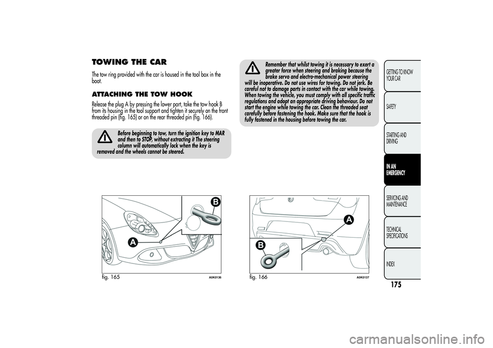
TOWING THE CARThe tow ring provided with the car is housed in the tool box in the
boot.ATTACHING THE TOW HOOKRelease the plug A by pressing the lower part, take the tow hook B
from its housing in the tool support and tighten it securely on the front
threaded pin (fig. 165) or on the rear threaded pin (fig. 166).
Before beginning to tow, turn the ignition key to MAR
and then to STOP, without extracting it The steering
column will automatically lock when the key is
removed and the wheels cannot be steered.
Remember that whilst towing it is necessary to exert a
greater force when steering and braking because the
brake servo and electro-mechanical power steering
will be inoperative. Do not use wires for towing. Do not jerk. Be
careful not to damage parts in contact with the car while towing.
When towing the vehicle, you must comply with all specific traffic
regulations and adopt an appropriate driving behaviour. Do not
start the engine while towing the car. Clean the threaded seat
carefully before fastening the hook. Make sure that the hook is
fully fastened in the housing before towing the car.
fig. 165
A0K0136
fig. 166
A0K0137
175GETTING TO KNOW
YOUR CAR
SAFETY
STARTING AND
DRIVINGIN AN
EMERGENCYSERVICING AND
MAINTENANCE
TECHNICAL
SPECIFICATIONS
INDEX


