2013.5 PEUGEOT 5008 ECU
[x] Cancel search: ECUPage 206 of 404
Checks
204
Bonnet
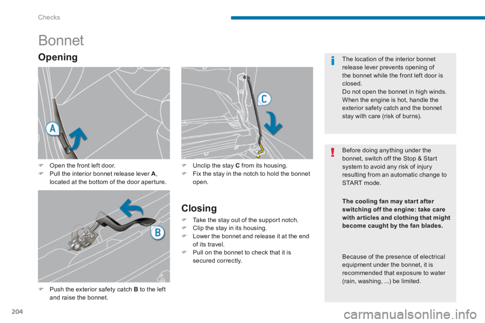
Push the exterior safety catch B to the left and raise the bonnet.
Unclip the stay C from its housing. Fix the stay in the notch to hold the bonnet open.
Closing
Take the stay out of the support notch. Clip the stay in its housing. Lower the bonnet and release it at the end of its travel. Pull on the bonnet to check that it is secured correctly.
Opening
Open the front left door. Pull the interior bonnet release lever A , located at the bottom of the door aperture.
Before doing anything under the bonnet, switch off the Stop & Start system to avoid any risk of injury resulting from an automatic change to START mode.
The location of the interior bonnet release lever prevents opening of the bonnet while the front left door is closed. Do not open the bonnet in high winds. When the engine is hot, handle the exterior safety catch and the bonnet stay with care (risk of burns).
The cooling fan may star t after switching off the engine: take care with articles and clothing that might become caught by the fan blades.
Because of the presence of electrical equipment under the bonnet, it is
recommended that exposure to water (rain, washing, ...) be limited.
Page 215 of 404
11
Practical information213
Temporary puncture repair kit
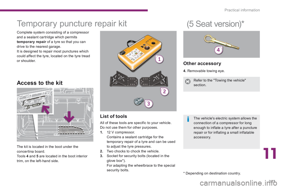
Complete system consisting of a compressor and a sealant cartridge which permits temporary repair of a tyre so that you can temporary repair of a tyre so that you can temporary repairdrive to the nearest garage. It is designed to repair most punctures which could affect the tyre, located on the tyre tread or shoulder.
List of tools
All of these tools are specific to your vehicle.
Do not use them for other purposes. 1. 12 V compressor. Contains a sealant cartridge for the temporary repair of a tyre and can be used to adjust the tyre pressures. 2. Two chocks to chock the vehicle. 3. Socket for security bolts (located in the glove box*) . For adapting the wheelbrace to the special security bolts.
Other accessory
4. Removable towing eye.
Access to the kit
(5 Seat version) *
The kit is located in the boot under the concertina board. To o l s 4 and 5 are located in the boot interior trim, on the left-hand side.
Refer to the "Towing the vehicle" section.
The vehicle's electric system allows the connection of a compressor for long
enough to inflate a tyre after a puncture repair or for inflating a small inflatable accessory.
* Depending on destination country.
Page 225 of 404
11
Practical information223
Changing a wheel *
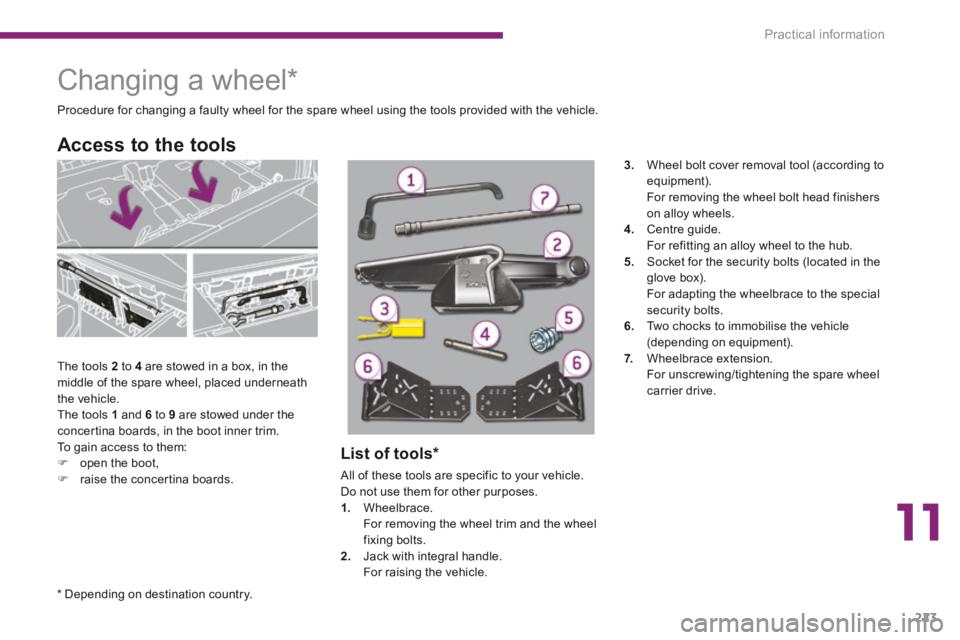
The tools 2 to 4 are stowed in a box, in the middle of the spare wheel, placed underneath the vehicle. The tools 1 and 6 to 9 are stowed under the concertina boards, in the boot inner trim. To gain access to them: open the boot, raise the concertina boards.
Access to the tools
Procedure for changing a faulty wheel for the spare wheel using the tools provided with the vehicle.
List of tools *
All of these tools are specific to your vehicle. Do not use them for other purposes. 1. Wheelbrace. For removing the wheel trim and the wheel fixing bolts. 2. Jack with integral handle. For raising the vehicle.
3. Wheel bolt cover removal tool (according to equipment). For removing the wheel bolt head finishers on alloy wheels. 4. Centre guide. For refitting an alloy wheel to the hub. 5. Socket for the security bolts (located in the glove box). For adapting the wheelbrace to the special security bolts. 6. Two chocks to immobilise the vehicle (depending on equipment). 7. Wheelbrace extension. For unscrewing/tightening the spare wheel carrier drive.
* Depending on destination country.
Page 229 of 404
11
Practical information227
Removing a wheel
List of operations
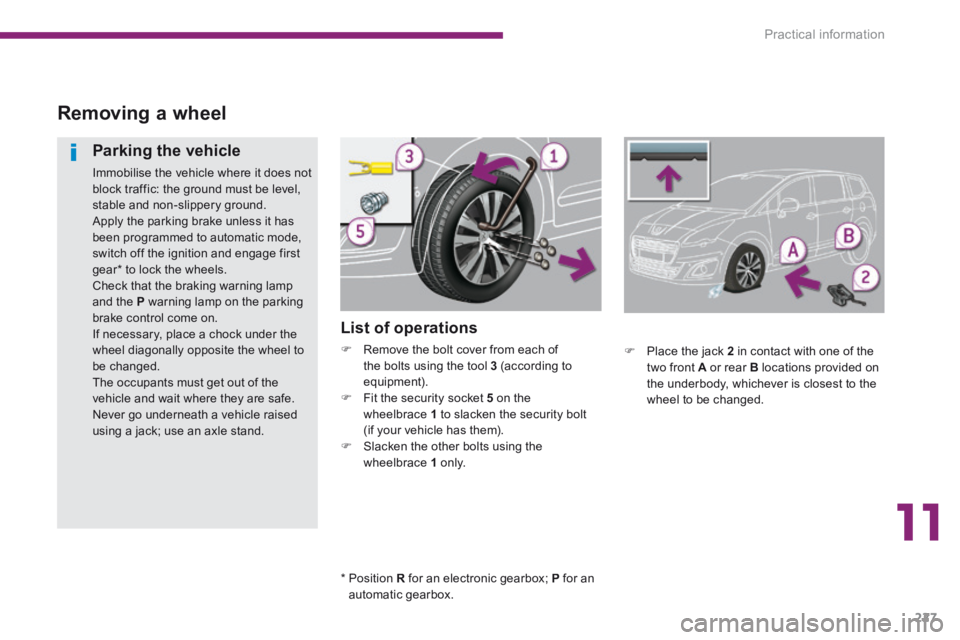
Remove the bolt cover from each of the bolts using the tool 3 (according to equipment). Fit the security socket 5 on the wheelbrace 1 to slacken the security bolt (if your vehicle has them). Slacken the other bolts using the wheelbrace 1 o n l y.
Parking the vehicle
Immobilise the vehicle where it does not block traffic: the ground must be level, stable and non-slippery ground. Apply the parking brake unless it has been programmed to automatic mode, switch off the ignition and engage first gear * to lock the wheels. Check that the braking warning lamp and the P warning lamp on the parking brake control come on. If necessary, place a chock under the wheel diagonally opposite the wheel to be changed. The occupants must get out of the vehicle and wait where they are safe. Never go underneath a vehicle raised using a jack; use an axle stand.
Place the jack 2 in contact with one of the two front A or rear B locations provided on the underbody, whichever is closest to the wheel to be changed.
* Position R for an electronic gearbox; P for an automatic gearbox.
Page 230 of 404

Practical information
228
Fitting the "space-saver" spare wheel
If your vehicle is fitted with alloy wheels, when tightening the bolts on fitting it is normal to notice that the washers do not come into contact with the "space-saver" spare wheel. The wheel is secured by the conical contact of each bolt.
After changing a wheel
To store the punctured wheel in the boot correctly, first remove the central cover. When using the "space-saver" type spare wheel, do not exceed 50 mph (80 km/h). Have the tightening of the bolts and the pressure of the spare wheel checked by a PEUGEOT dealer or a qualified workshop without delay. Have the punctured wheel repaired and replace it on the vehicle as soon as possible.
Position the base plate of the jack on the ground and ensure that it is directly below the location A or B used. Extend the jack until its head is in contact with A or B . Raise the vehicle until there is sufficient space between the wheel and the ground
to admit the spare (not punctured) wheel easily.
Remove the bolts and store them in a clean place. Remove the wheel.
Ensure that the jack is stable. If the ground is slippery or loose, the jack might slip and drop. Position the jack only at the locations Aor B . Ensure that the head of the jack is positioned centrally on the jacking location. Otherwise there is a risk of damage to the vehicle and the jack may drop.
Page 231 of 404
11
Practical information229
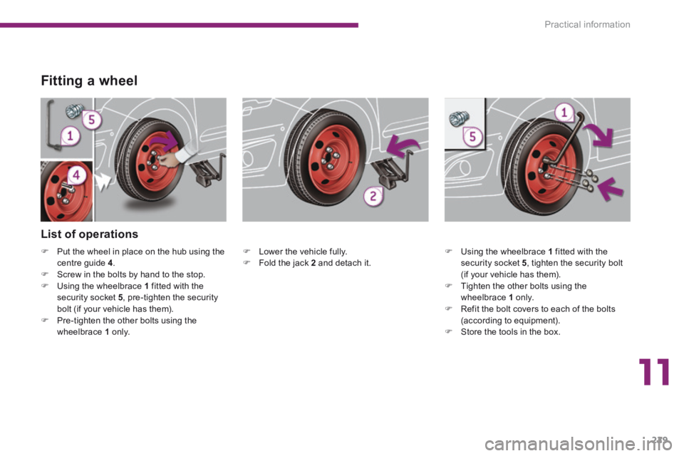
Fitting a wheel
Lower the vehicle fully. Fold the jack 2 and detach it.
List of operations
Using the wheelbrace 1 fitted with the security socket 5 , tighten the security bolt (if your vehicle has them). Tighten the other bolts using the wheelbrace 1 o n l y. Refit the bolt covers to each of the bolts (according to equipment). Store the tools in the box.
Put the wheel in place on the hub using the centre guide 4 . Screw in the bolts by hand to the stop. Using the wheelbrace 1 fitted with the security socket 5 , pre-tighten the security bolt (if your vehicle has them). Pre-tighten the other bolts using the wheelbrace 1 o n l y.
Page 246 of 404
Practical information
244
1 2 V b a t t e r y
Access to the battery
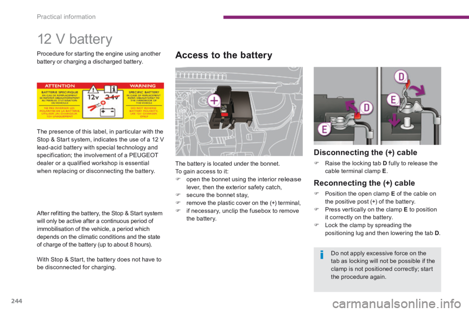
The battery is located under the bonnet. To gain access to it: open the bonnet using the interior release lever, then the exterior safety catch, secure the bonnet stay, remove the plastic cover on the (+) terminal, if necessary, unclip the fusebox to remove the battery.
Disconnecting the (+) cable
Raise the locking tab D fully to release the cable terminal clamp E .
Reconnecting the (+) cable
Position the open clamp E of the cable on the positive post (+) of the battery. Press vertically on the clamp E to position it correctly on the battery. Lock the clamp by spreading the positioning lug and then lowering the tab D .
The presence of this label, in particular with the Stop & Start system, indicates the use of a 12 V lead-acid battery with special technology and specification; the involvement of a PEUGEOT dealer or a qualified workshop is essential when replacing or disconnecting the battery.
After refitting the battery, the Stop & Start system will only be active after a continuous period of immobilisation of the vehicle, a period which depends on the climatic conditions and the state of charge of the battery (up to about 8 hours).
With Stop & Start, the battery does not have to be disconnected for charging.
Procedure for starting the engine using another battery or charging a discharged battery.
Do not apply excessive force on the
tab as locking will not be possible if the clamp is not positioned correctly; start the procedure again.
Page 256 of 404

Practical information
254
"Protection"
Mats * , boot liner, luggage net, style mud flaps ** , seat covers, pet range, boot sill protector...
"Safety and security"
Anti-theft alarm, window etching, wheel security bolts, child seats and booster cushions, first aid kit, breathalyzer, warning triangle, high visibility vest, stolen vehicle tracking system, dog guard, winter equipment (snow chains, non-slip covers...)...
Accessories
"Style"
Alloy wheels, door sill trims, chrome-plated door handle shells, spoiler, gear lever knob...
"Transport solutions"
Roof bars, towbars, bicycle carrier on towbar, bicycle carrier on roof bars, ski carrier, rigid and flexible roof boxes... Trailer towbar, which must be fitted by a PEUGEOT dealer.
"Comfort"
Door deflectors, parking sensors, side window
blinds, coat-hanger, insulated module...
A wide range of accessories and genuine parts is available from the PEUGEOT dealer network. These accessories and parts have been tested and approved for reliability and safety. They are all adapted to your vehicle and benefit from PEUGEOT's recommendation and warranty.
* To avoid any risk of jamming of the pedals: - ensure that the mat is positioned and secured correctly, - never fit one mat on top of another.
** The configuration of the vehicle requires that it be fitted with mud flaps at the rear.