2013.5 Peugeot 308 CC gearbox
[x] Cancel search: gearboxPage 158 of 268
10
156
PRACTICAL INFORMATION
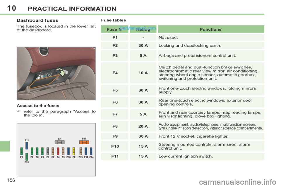
Dashboard fuses
The fusebox is located in the lower left
of the dashboard.
Access to the fuses
refer to the paragraph "Access to the tools". Fuse tables
Fuse N° Rating Functions
F1 - Not used.
F2 30 A Locking and deadlocking earth.
F3 5 A Airbags and pretensioners control unit.
F4 10 A Clutch pedal and dual-function brake switches,
electrochromatic rear view mirror, air conditioning,
steering wheel angle sensor, automatic gearbox,
switching and protection unit.
F5 30 A Front one-touch electric windows, folding mirrors
supply.
F6 30 A Rear one-touch electric windows, exterior door
opening controls.
F7 5 A Front and rear courtesy lamps, map reading lamps,
sun visor lighting, glove box lighting.
F8 20 A
Audio equipment, audio/telephone, multifunction screen,
tyre under-infl ation detection, interior storage compartments.
F9 30 A Front 12 V socket, cigarette lighter.
F10 15 A Steering mounted controls, alarm siren, alarm
control unit.
F 11 15 A Low current ignition switch.
Page 160 of 268
10
158
PRACTICAL INFORMATION
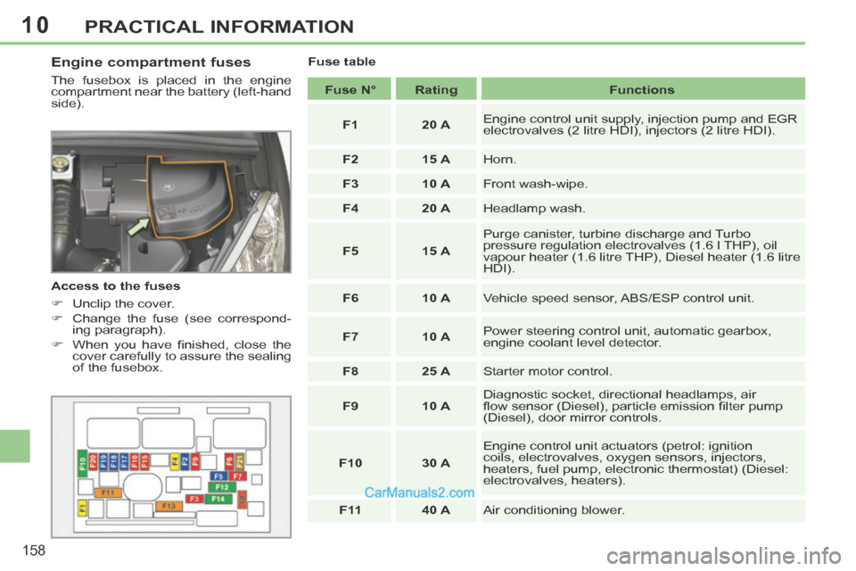
Engine compartment fuses
The fusebox is placed in the engine
compartment near the battery (left-hand
side).
Access to the fuses
Unclip the cover.
Change the fuse (see correspond-ing paragraph).
When you have fi nished, close the cover carefully to assure the sealing
of the fusebox. Fuse table
Fuse N° Rating Functions
F1 20 A Engine control unit supply, injection pump and EGR
electrovalves (2 litre HDI), injectors (2 litre HDI).
F2 15 A Horn.
F3 10 A Front wash-wipe.
F4 20 A Headlamp wash.
F5 15 A Purge canister, turbine discharge and Turbo
pressure regulation electrovalves (1.6 l THP), oil
vapour heater (1.6 litre THP), Diesel heater (1.6 litre
HDI).
F6 10 A Vehicle speed sensor, ABS/ESP control unit.
F7 10 A Power steering control unit, automatic gearbox,
engine coolant level detector.
F8 25 A Starter motor control.
F9 10 A Diagnostic socket, directional headlamps, air
fl ow sensor (Diesel), particle emission fi lter pump
(Diesel), door mirror controls.
F10 30 A Engine control unit actuators (petrol: ignition
coils, electrovalves, oxygen sensors, injectors,
heaters, fuel pump, electronic thermostat) (Diesel:
electrovalves, heaters).
F 11 40 A Air conditioning blower.
Page 162 of 268
10
!
160
PRACTICAL INFORMATION
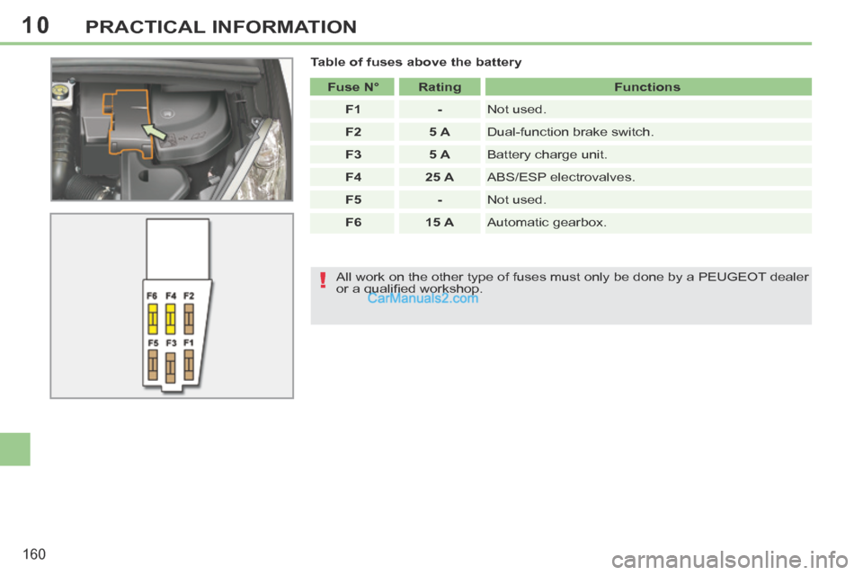
Table of fuses above the battery Fuse N° Rating Functions
F1 - Not used.
F2 5 A Dual-function brake switch.
F3 5 A Battery charge unit.
F4 25 A ABS/ESP electrovalves.
F5 - Not used.
F6 15 A Automatic gearbox.
All work on the other type of fuses must only be done by a PEUGEOT dealer
or a qualifi ed workshop.
Page 163 of 268
10
!
i
i
!
161
PRACTICAL INFORMATION
12 V BATTERY
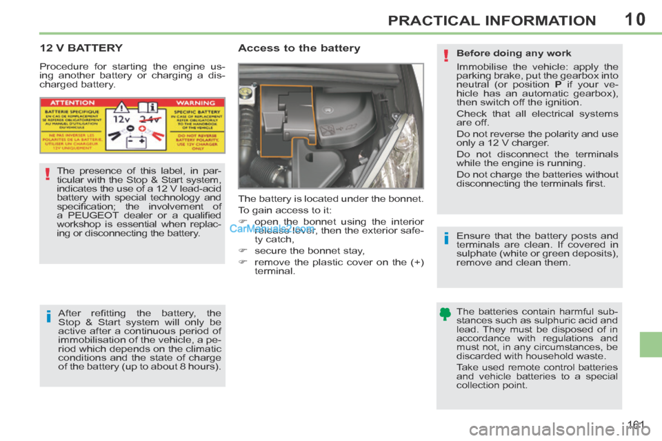
Access to the battery
The battery is located under the bonnet.
To gain access to it:
open the bonnet using the interior release lever, then the exterior safe-
ty catch,
secure the bonnet stay,
remove the plastic cover on the (+) terminal.
The presence of this label, in par-
ticular with the Stop & Start system,
indicates the use of a 12 V lead-acid
battery with special technology and
specifi cation; the involvement of
a PEUGEOT dealer or a qualifi ed
workshop is essential when replac-
ing or disconnecting the battery.
After refi tting the battery, the
Stop & Start system will only be
active after a continuous period of
immobilisation of the vehicle, a pe-
riod which depends on the climatic
conditions and the state of charge
of the battery (up to about 8 hours).
Procedure for starting the engine us-
ing another battery or charging a dis-
charged battery.
Before doing any work
Immobilise the vehicle: apply the
parking brake, put the gearbox into
neutral (or position
P if your ve-
hicle has an automatic gearbox),
then switch off the ignition.
Check that all electrical systems
are off.
Do not reverse the polarity and use
only a 12 V charger.
Do not disconnect the terminals
while the engine is running.
Do not charge the batteries without
disconnecting the terminals fi rst.
Ensure that the battery posts and
terminals are clean. If covered in
sulphate (white or green deposits),
remove and clean them.
The batteries contain harmful sub-
stances such as sulphuric acid and
lead. They must be disposed of in
accordance with regulations and
must not, in any circumstances, be
discarded with household waste.
Take used remote control batteries
and vehicle batteries to a special
collection point.
Page 167 of 268
10
i
165
PRACTICAL INFORMATION
CHANGING A WIPER BLADE
Removing
Raise the corresponding wiper arm.
Unclip the wiper blade and remove it.
Fitting
Put the corresponding new wiper blade in place and clip it.
Fold down the wiper arm carefully.
Before removing a front wiper
blade
Within one minute after switching off the ignition, operate the wiper stalk
to position the wiper blades verti-
cally on the windscreen.
After fitting a front wiper blade
Switch on the ignition.
Operate the wiper stalk again to park the wiper blades.
TOWING THE VEHICLE
Procedure for having your vehicle
towed or for towing another vehicle us-
ing a removable towing eye.
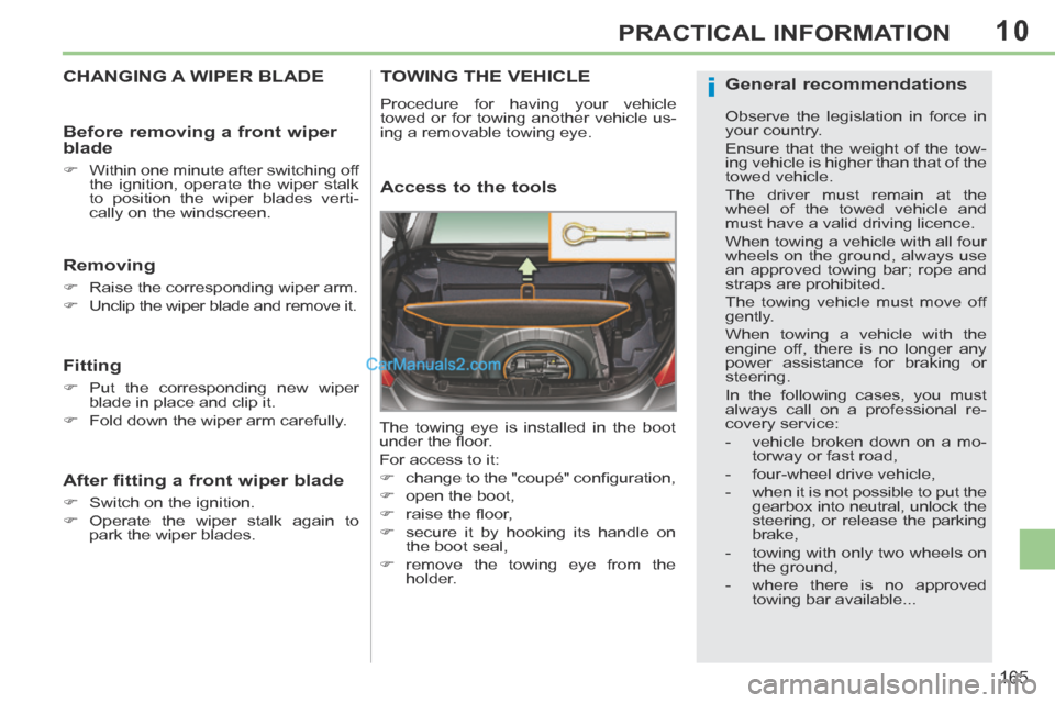
Access to the tools
The towing eye is installed in the boot
under the fl oor.
For access to it:
change to the "coupé" confi guration,
open the boot,
raise the fl oor,
secure it by hooking its handle on the boot seal,
remove the towing eye from the holder.
General recommendations
Observe the legislation in force in
your country.
Ensure that the weight of the tow-
ing vehicle is higher than that of the
towed vehicle.
The driver must remain at the
wheel of the towed vehicle and
must have a valid driving licence.
When towing a vehicle with all four
wheels on the ground, always use
an approved towing bar; rope and
straps are prohibited.
The towing vehicle must move off
gently.
When towing a vehicle with the
engine off, there is no longer any
power assistance for braking or
steering.
In the following cases, you must
a lways call on a professional re-
covery service:
- vehicle broken down on a mo-torway or fast road,
- four-wheel drive vehicle,
- when it is not possible to put the gearbox into neutral, unlock the
steering, or release the parking
brake,
- towing with only two wheels on the ground,
- where there is no approved towing bar available...
Page 168 of 268
10
i
166
PRACTICAL INFORMATION
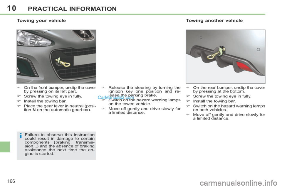
Towing your vehicle
On the front bumper, unclip the cover by pressing on its left part.
Screw the towing eye in fully.
Install the towing bar.
Place the gear lever in neutral (posi- tion N on the automatic gearbox). Release the steering by turning the
ignition key one position and re-
lease the parking brake.
Switch on the hazard warning lamps on the towed vehicle.
Move off gently and drive slowly for a limited distance.
Failure to observe this instruction
could result in damage to certain
components (braking, transmis-
sion...) and the absence of braking
assistance the next time the en-
gine is started. On the rear bumper, unclip the cover
by pressing at the bottom.
Screw the towing eye in fully.
Install the towing bar.
Switch on the hazard warning lamps on both vehicles.
Move off gently and drive slowly for a limited distance.
Towing another vehicle
Page 172 of 268
11
170
TECHNICAL DATA
* The maximum power corresponds to the value type-approved on a test bed, under conditions defi ned in European legislation (Directive 1999/99/EC).
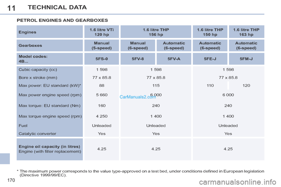
PETROL ENGINES AND GEARBOXES
Engines 1.6 litre VTi
120 hp 1.6 litre THP
156 hp 1.6 litre THP
150 hp 1.6 litre THP
163 hp
Gearboxes Manual
(5-speed) Manual
(6-speed) Automatic
(6-speed) Automatic
(6-speed) Automatic
(6-speed)
Model codes:
4B... 5FS-0
5FV-8 5FV-A 5FE-J 5FM-J
Cubic capacity (cc) 1 598 1 598 1 598
Bore x stroke (mm) 77 x 85.8 77 x 85.8 77 x 85.8
Max power: EU standard (kW) * 88 115 110 120
Max power engine speed (rpm) 5 660 6 000 6 000
Max torque: EU standard (Nm) 160 240 240
Max torque engine speed (rpm) 4 250 1 400 1 400
Fuel Unleaded Unleaded Unleaded
Catalytic converter Yes Yes Yes
Engine oil capacity (in litres)
Engine (with fi lter replacement) 4.25
4.25 4.25
Page 173 of 268
11
171
TECHNICAL DATA
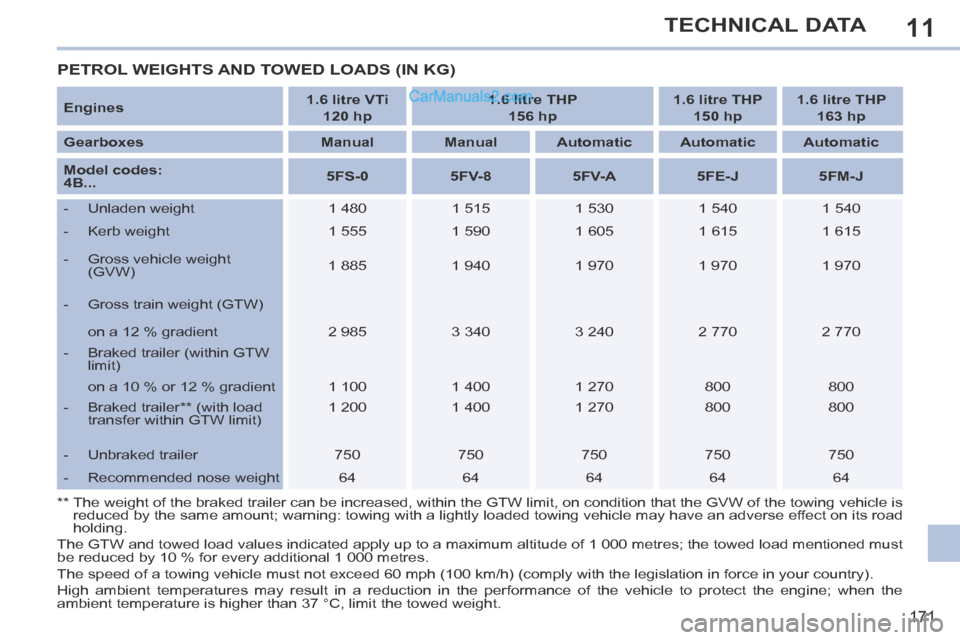
PETROL WEIGHTS AND TOWED LOADS (IN KG)
Engines 1.6 litre VTi
120 hp 1.6 litre THP
156 hp 1.6 litre THP
150 hp 1.6 litre THP
163 hp
Gearboxes Manual Manual Automatic Automatic Automatic
Model codes:
4B... 5FS-0
5FV-8 5FV-A 5FE-J 5FM-J
- Unladen weight 1 480 1 515 1 530 1 540 1 540
- Kerb weight 1 555 1 590 1 605 1 615 1 615
- Gross vehicle weight (GVW) 1 885
1 940 1 970 1 970 1 970
- Gross train weight (GTW)
on a 12 % gradient 2 985 3 340 3 240 2 770 2 770
- Braked trailer (within GTW limit)
on a 10 % or 12 % gradient 1 100 1 400 1 270 800 800
- Braked trailer ** (with load transfer within GTW limit) 1 200
1 400 1 270 800 800
- Unbraked trailer 750 750 750 750 750
- Recommended nose weight 64 64 64 64 64
** The weight of the braked trailer can be increased, within the GTW limit,\
on condition that the GVW of the towing vehicle is reduced by the same amount; warning: towing with a lightly loaded towing\
vehicle may have an adverse effect on its road
holding.
The GTW and towed load values indicated apply up to a maximum altitude o\
f 1 000 metres; the towed load mentioned must
be reduced by 10 % for every additional 1 000 metres.
The speed of a towing vehicle must not exceed 60 mph (100 km/h) (comp\
ly with the legislation in force in your country).
High ambient temperatures may result in a reduction in the performance of the vehicle to protect the engine; when the
a mbient temperature is higher than 37 °C, limit the towed weight.